EP1306116B1 - Apparatus for removing particles from a fluid stream - Google Patents
Apparatus for removing particles from a fluid stream Download PDFInfo
- Publication number
- EP1306116B1 EP1306116B1 EP02023529.7A EP02023529A EP1306116B1 EP 1306116 B1 EP1306116 B1 EP 1306116B1 EP 02023529 A EP02023529 A EP 02023529A EP 1306116 B1 EP1306116 B1 EP 1306116B1
- Authority
- EP
- European Patent Office
- Prior art keywords
- shell
- flow
- outlet
- inlet
- flume
- Prior art date
- Legal status (The legal status is an assumption and is not a legal conclusion. Google has not performed a legal analysis and makes no representation as to the accuracy of the status listed.)
- Expired - Lifetime
Links
- 239000002245 particle Substances 0.000 title claims description 10
- 239000012530 fluid Substances 0.000 title claims description 3
- 239000007788 liquid Substances 0.000 claims description 42
- 239000007787 solid Substances 0.000 claims description 2
- 238000000605 extraction Methods 0.000 claims 4
- 230000000149 penetrating effect Effects 0.000 claims 1
- 238000011144 upstream manufacturing Methods 0.000 claims 1
- 230000009471 action Effects 0.000 description 2
- 230000007423 decrease Effects 0.000 description 2
- 238000000034 method Methods 0.000 description 2
- 239000010865 sewage Substances 0.000 description 2
- 238000009825 accumulation Methods 0.000 description 1
- 230000003466 anti-cipated effect Effects 0.000 description 1
- 230000004888 barrier function Effects 0.000 description 1
- 230000008859 change Effects 0.000 description 1
- 230000003247 decreasing effect Effects 0.000 description 1
- 230000003028 elevating effect Effects 0.000 description 1
- 230000001939 inductive effect Effects 0.000 description 1
- 238000009434 installation Methods 0.000 description 1
- 230000002093 peripheral effect Effects 0.000 description 1
- 230000002265 prevention Effects 0.000 description 1
- 230000008569 process Effects 0.000 description 1
- 238000005086 pumping Methods 0.000 description 1
- 230000003014 reinforcing effect Effects 0.000 description 1
- 239000002002 slurry Substances 0.000 description 1
- 239000010409 thin film Substances 0.000 description 1
- XLYOFNOQVPJJNP-UHFFFAOYSA-N water Substances O XLYOFNOQVPJJNP-UHFFFAOYSA-N 0.000 description 1
Images


Classifications
-
- B—PERFORMING OPERATIONS; TRANSPORTING
- B01—PHYSICAL OR CHEMICAL PROCESSES OR APPARATUS IN GENERAL
- B01D—SEPARATION
- B01D21/00—Separation of suspended solid particles from liquids by sedimentation
- B01D21/26—Separation of sediment aided by centrifugal force or centripetal force
-
- B—PERFORMING OPERATIONS; TRANSPORTING
- B01—PHYSICAL OR CHEMICAL PROCESSES OR APPARATUS IN GENERAL
- B01D—SEPARATION
- B01D21/00—Separation of suspended solid particles from liquids by sedimentation
- B01D21/24—Feed or discharge mechanisms for settling tanks
-
- B—PERFORMING OPERATIONS; TRANSPORTING
- B01—PHYSICAL OR CHEMICAL PROCESSES OR APPARATUS IN GENERAL
- B01D—SEPARATION
- B01D21/00—Separation of suspended solid particles from liquids by sedimentation
- B01D21/24—Feed or discharge mechanisms for settling tanks
- B01D21/2405—Feed mechanisms for settling tanks
- B01D21/2411—Feed mechanisms for settling tanks having a tangential inlet
-
- B—PERFORMING OPERATIONS; TRANSPORTING
- B01—PHYSICAL OR CHEMICAL PROCESSES OR APPARATUS IN GENERAL
- B01D—SEPARATION
- B01D21/00—Separation of suspended solid particles from liquids by sedimentation
- B01D21/24—Feed or discharge mechanisms for settling tanks
- B01D21/2444—Discharge mechanisms for the classified liquid
Definitions
- the present invention relates to an extracting device that uses the flow of the liquid through a hydraulic system for removing grit or other particles from a solid-laden liquid.
- a known grit extractor apparatus for liquid sewage includes inlet and outlet troughs or flumes connected to a round settling chamber. This type of apparatus can have a typical flow rate turn down ratio of about four to one.
- EP 0 292 020 like GB 2 148 744 A , discloses a grit selector having an upper settling chamber and a lower grit storage chamber. Therein, an influent flume is directed along the floor of the settling chamber to the peripheral wall and is circulated likewise.
- US 4,270,676 A discloses slurry feed distributors.
- flow velocity can be a critical factor in determining turn down ratio.
- the flow velocity can advantageously be maintained between about 0.46 meter [1.5 feet] per second to about 1.07 meter [3.5 feet] per second.
- a flow velocity below 0.46 meter [1.5 feet] per second could under certain circumstances tend to allow grit to settle in the extractor troughs where it is difficult to remove by the flow stream. As a result, the troughs have to be manually cleaned.
- the flow can under certain circumstances be turbulent. When the flow is too turbulent, at velocity above e.g. 1.07 meter [3.5 feet] per second, the grit will not move to the bottom of the flow stream where it can effectively attach to the bottom of the chamber, and will not remain on the bottom of the chamber to be moved to a central grit storage chamber.
- Grit extractor apparatus are disclosed in U.S. Patents 4,767,532 ; 4,107,038 ; and 3,941,698 .
- the grit extractor apparatus of these patents introduce the liquid and grit into a round chamber wherein the resultant hydraulics within the chamber control the degree of grit removal.
- This tendency can result in some short circuiting across the chamber, especially at low flows, resulting in less than optimum grit removal.
- the effluent flow from the round chamber is over a broad area.
- the outflow has a large radial vector that results in decreasing the circular velocity, due to being at right angles to the circular flow. Reduced circular velocity can result in inefficient velocity to move grit, causing grit build up on the floor of the chamber, especially at low liquid flow rates.
- the present inventors have recognized the desirability of providing a grit extractor apparatus that can be designed also for future anticipated higher flow rates, and yet be able to effectively operate for present day smaller flow rates. For example, if a difference in daily peak flow to minimum daily flow is about three to one to four to one, it is understandable that a future peak or maximum flow rate incorporated into a design may be projected to a larger amount, such as twice as large as the present maximum flow rate, such that the turn down ratio from the present minimum flows to the future maximum or peak flows will be e.g. six to one to eight to one.
- the present inventors have recognized the desirability of also being able to reduce the area or "footprint" of such extractor apparatus to fit the apparatus inside existing buildings, to install larger extractor apparatus in the same space that an existing extractor apparatus occupies, or in order to minimize space in a new plant, if desired.
- the disclosure also relates to a method of removing solid particles from a liquid.
- a grit extractor apparatus can achieve optimum grit removal by using hydraulic currents to rotate grit-laden liquid so the grit comes in contact with the bottom of the grit removal chamber at a sufficiently slow velocity to be deposited on the bottom.
- the velocity is sufficiently fast such that hydraulic currents generate a moving force that gently pushes the grit along the floor of the chamber to the center where the grit is collected in a storage chamber for removal.
- the embodiments of the present invention incorporate novel structure to control the flow of liquid and grit within a circular chamber and within inlet and outlet troughs or flumes.
- the flow velocity entering and leaving the chamber can be controlled by the width of the entrance of the outlet flume.
- the velocity can be controlled over e.g. a ten to one flow range by the preferred novel use of hydraulic phenomena of the fluid level entering a narrow flume.
- a e.g. ten to one variation in flow can be achieved with an effective flow velocity in the range of e.g. 0.46 meter [1.5 feet] per second to 1.07 meter [3.5 feet] per second.
- Hydraulic control of flow velocity can preferably be incorporated inside of the grit chamber instead of outside of the chamber, as in existing grit removal devices. This feature can reduce the area that the unit occupies and greatly reduce the installation footprint.
- the grit extractor apparatus of the invention can increase efficiency of grit removal.
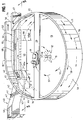
- FIG 1 illustrates an apparatus 10 for separating grit from grit-laden liquid 71 entering the apparatus.
- An inlet trough 40 has an inlet conduit 41 that conveys the liquid 71 downwardly at a slight angle.
- the conduit 41 turns to the horizontal adjacent to a grit removal chamber 11.
- a trough bottom 43 is at the same elevation as a bottom 13 of the grit removal chamber 11.
- One vertical wall 42 of the conduit 41 is tangent to a wall 22 of the chamber 11 where the wall 42 terminates.
- a vertical wall 44 is parallel to the wall 42 and enters the chamber wall 22 at an inlet location 48 (shown in Figure 3 ).
- a wall 45 extends across the chamber 11 to an inlet opening 46 where the grit-laden liquid enters chamber 11, flowing circumferentially around the wall 22 of the chamber.
- a top 47 of the conduit 41 is parallel to the bottom 13 and becomes the bottom of an effluent flume 55 that extends across the chamber 11.
- An influent tunnel is formed by the top 47, which is the bottom 64 of an effluent flume 55, the wall 45, the floor 13 and the wall 22.
- One example of a grit removal chamber includes a 5.49 meter [18 feet] diameter, 2.74 meter [9 feet] tall wall 22 for a 114 million liter [30 million gallons] per day flow rate.
- the grit-laden liquid flows from the opening 46 around the inside perimeter of the chamber 11, forming a lower channel of flow 56 as shown by the dashed arrows.
- the grit in this liquid comes in contact with the floor as the liquid is forced into a thin film, spread across the floor 13.
- the grit contacts the floor and is deposited on the floor.
- the spiral movement of flow 57 moves the grit across the floor 13 to the center hole 15.
- the result is a pumping action across the floor 13, upward from the paddle, inducing additional pushing action on the grit.
- the flow moves across the surface of the liquid in the same manner as the centrifugal force, reinforcing the centrifugal force.
- the grit moves across the floor, drops down the center hole 15 into the grit storage chamber below (not shown).
- the bottom 13 may be flat or sloped downwardly toward the center hole.
- the grit storage chamber and grit removal apparatus can be as disclosed in U.S. Patents 4,767,532 ; 4,107038 or 3,941,698 .
- the wall 45 and the shelf 64 operate in unison to define the upper and lower channels of flow 56, 58 flowing around the shell inside perimeter.
- the lower channel of flow 56 flows under a shelf 64 and is deflected by the wall 45. Trapped between the shelf 64, the wall 22, the floor 13, and a more slowly rotating inner cylinder of liquid 59, the lower channel of flow 56 is forced upwardly.
- the channel of flow is now in the upper half of the liquid height, forming an upper channel of flow 58 that flows around an upper perimeter of the chamber adjacent to the wall 22, as shown by the dotted arrows.
- the upper channel of flow 58 flows into an outlet opening 65a formed by a flume 65 defined by the wall 22, a wall 62, and a floor 64.
- the width Y of an opening 65a into the flume is narrower than the entrance width W of the inlet trough 40. This narrower opening results in a higher liquid level in grit removal chamber 11 to force the incoming flow through the more narrow opening 65a.
- the liquid flows through the flume 65 into an exit flume 66 defined by a wall 52 extended from the wall 22, a wall 60 and a floor 67.
- influent velocity between about 1.5 feet per second (0.46 meter per second) and 3.5 feet per second (1.07 meter per second) at all process flows.
- influent velocity between about 1.5 feet per second (0.46 meter per second) and 3.5 feet per second (1.07 meter per second) at all process flows.
- the larger grit settled out of the flow stream will move along the bottom and smaller grit in the flow stream will be in heavier concentration near the bottom.
- the grit will be easier to remove as it is already on or near the bottom of the flow stream. If the flow velocity is too low, however, the heavy grit settled on the bottom will not be moved along the bottom. This results in grit accumulating in the inlet flumes and not in the chamber.
- the velocity range of 1.5 feet per second to 3.5 feet per second (0.46 to 1.07 meter per second) has been determined to be an effective operating range.
- Figure 2 shows the relation of various grit sizes in the flow stream at various velocities. Liquid velocity between 1.5 feet per second and 3.5 feet per second (0.46 to 1.07 meter per second) yields the optimum settling and bed flow for grit sizes most likely present in large quantity in sewage water.
- the dimension Y of the flume 65 can be varied. This controls the depth of liquid 70 in the grit chamber 11, which reflects back to the height H of liquid in the influent trough 40.
- the entrance width W of the influent trough 40 is fixed for a certain flow unit. If H is varied in proper flow ratio, the influent flow will remain within the prescribed velocity range at the various flows.
- the opening 46 controls the influent velocity into the grit removal chamber 11.
- the opening height is the same as the height of the wall 44.
- the width of the opening is:
- the channel of flow 56 is formed passing around the inside perimeter of the grit chamber 11.
- the upper channel of flow 58 further defines and confines the channel of flow 56 around the inside periphery of the wall 22.
- the upper and lower channels of flows 56, 58 have approximately the same dimension flowing around the inside perimeter of the wall 22.
- the top 47 of the tunnel causes the flow to move out in a straight manner like a nozzle.
- the upper rotating formed channel of flow 58 moves over the entering liquid that forms the lower channel of flow 56. This prevents back eddy currents at the top of the lower channel of flow 56. The result is the liquid entering the chamber 11 remains as a formed lower channel of flow 56.
- the projection Z also confines the rotating channel 58, that is formed clockwise past the flume 65, to the dimension of the formed channel entering the flume 65.
- the perimeter wall 22 acts like the bottom of a channel.
- the floor 13 of the chamber 11 acts like the side of a channel.
- the bottom 64 of the flume 65 acts like the side of a channel.
- the upper formed channel of flow 58 moves around the wall 60 and the perimeter wall 22 to the exit flume 65 at approximately the same velocity and dimension as the lower formed channel of flow 56.
- Each formed channel of flow is about half the depth of the chamber 11.
- the width Y of the flume is 0.915 meter [3 feet]
- the height of flow exiting is 0.894 meter [2.93 feet]
- the velocity of the formed channel is about the average of the inlet and outlet velocity. At the minimum, it is readily seen that the velocity in the chamber never drops below the minimum velocity, to keep grit moving at sufficient velocity.
- the height of the liquid rotating in the chamber 11 reduces as the influent flow decreases.
- the decrease in height at 1/10 maximum flow is almost one half. This means that there is less mass of liquid to rotate. A smaller mass results in less velocity of incoming liquid required to keep rotational velocity. This is demonstrated by the fact that at a drop of inlet velocity to 1/10 maximum velocity, the rotational speed only drops to about one half of maximum required velocity of 1.07 meter [3.5 feet] per second to 0.49 meter [1,6 feet] per second rotational velocity.
Landscapes
- Chemical & Material Sciences (AREA)
- Chemical Kinetics & Catalysis (AREA)
- Separation Of Solids By Using Liquids Or Pneumatic Power (AREA)
- Extraction Or Liquid Replacement (AREA)
- Cyclones (AREA)
- Physical Or Chemical Processes And Apparatus (AREA)
- Measuring Volume Flow (AREA)
- Centrifugal Separators (AREA)
Description
- The present invention relates to an extracting device that uses the flow of the liquid through a hydraulic system for removing grit or other particles from a solid-laden liquid.
- A known grit extractor apparatus for liquid sewage includes inlet and outlet troughs or flumes connected to a round settling chamber. This type of apparatus can have a typical flow rate turn down ratio of about four to one.
-
EP 0 292 020GB 2 148 744 A -
US 4,270,676 A discloses slurry feed distributors. - In the known grit extractor apparatus, flow velocity can be a critical factor in determining turn down ratio. The flow velocity can advantageously be maintained between about 0.46 meter [1.5 feet] per second to about 1.07 meter [3.5 feet] per second. A flow velocity below 0.46 meter [1.5 feet] per second could under certain circumstances tend to allow grit to settle in the extractor troughs where it is difficult to remove by the flow stream. As a result, the troughs have to be manually cleaned. For a flow velocity above 0.46 meter [1.5 feet] per second, the flow can under certain circumstances be turbulent. When the flow is too turbulent, at velocity above e.g. 1.07 meter [3.5 feet] per second, the grit will not move to the bottom of the flow stream where it can effectively attach to the bottom of the chamber, and will not remain on the bottom of the chamber to be moved to a central grit storage chamber.
- Grit extractor apparatus are disclosed in
U.S. Patents 4,767,532 ;4,107,038 ; and3,941,698 . The grit extractor apparatus of these patents introduce the liquid and grit into a round chamber wherein the resultant hydraulics within the chamber control the degree of grit removal. There is a natural tendency in this extractor apparatus for the hydraulic flow to pass from the influent to the effluent as rapidly as possible. This tendency can result in some short circuiting across the chamber, especially at low flows, resulting in less than optimum grit removal. The effluent flow from the round chamber is over a broad area. The outflow has a large radial vector that results in decreasing the circular velocity, due to being at right angles to the circular flow. Reduced circular velocity can result in inefficient velocity to move grit, causing grit build up on the floor of the chamber, especially at low liquid flow rates. - There is little control of liquid flow velocity entering the chamber, as flow velocity is a function of flume width, which is a set dimension, the quantity of liquid flowing, and the height of the liquid flowing in the flume. If the velocity is too great, the grit is uniformly suspended or distributed in the flow. Uniform distributed grit is harder to recover. If the level in the inlet or influent flume is raised, by elevating the level of the outlet or effluent flume, the velocity at low flows will be low and cause grit accumulation in the chamber or in the influent flume. Because of these design restraints, a typical e.g. four to one turn down ratio can be a design limitation.
- The present inventors have recognized the desirability of providing a grit extractor apparatus that can be designed also for future anticipated higher flow rates, and yet be able to effectively operate for present day smaller flow rates. For example, if a difference in daily peak flow to minimum daily flow is about three to one to four to one, it is understandable that a future peak or maximum flow rate incorporated into a design may be projected to a larger amount, such as twice as large as the present maximum flow rate, such that the turn down ratio from the present minimum flows to the future maximum or peak flows will be e.g. six to one to eight to one.
- The present inventors have recognized the desirability of also being able to reduce the area or "footprint" of such extractor apparatus to fit the apparatus inside existing buildings, to install larger extractor apparatus in the same space that an existing extractor apparatus occupies, or in order to minimize space in a new plant, if desired.
- The invention is defined in the appended claims.
- The disclosure also relates to a method of removing solid particles from a liquid.
- A grit extractor apparatus according to embodiments of the present invention can achieve optimum grit removal by using hydraulic currents to rotate grit-laden liquid so the grit comes in contact with the bottom of the grit removal chamber at a sufficiently slow velocity to be deposited on the bottom. The velocity is sufficiently fast such that hydraulic currents generate a moving force that gently pushes the grit along the floor of the chamber to the center where the grit is collected in a storage chamber for removal.
- The embodiments of the present invention incorporate novel structure to control the flow of liquid and grit within a circular chamber and within inlet and outlet troughs or flumes. The flow velocity entering and leaving the chamber can be controlled by the width of the entrance of the outlet flume. The velocity can be controlled over e.g. a ten to one flow range by the preferred novel use of hydraulic phenomena of the fluid level entering a narrow flume. According to the embodiments of the present invention, a e.g. ten to one variation in flow can be achieved with an effective flow velocity in the range of e.g. 0.46 meter [1.5 feet] per second to 1.07 meter [3.5 feet] per second.
- Hydraulic control of flow velocity can preferably be incorporated inside of the grit chamber instead of outside of the chamber, as in existing grit removal devices. This feature can reduce the area that the unit occupies and greatly reduce the installation footprint. The grit extractor apparatus of the invention can increase efficiency of grit removal.
- Numerous other possible advantages and preferred features of the present invention will become readily apparent from the following detailed description of the invention and the embodiments thereof, from the claims and from the accompanying drawings.
-
-
Figure 1 is a schematic sectional view of a grit extractor apparatus of the present invention; -
Figure 2 is a graphical depiction of flow stream curves; -
Figure 3 is a schematic plan view of a lower level of the apparatus ofFigure 1 ; -
Figure 4 is a schematic plan view of an upper level of the apparatus ofFigure 1 ; and -
Figure 5 is a schematic sectional view taken along line 5-5 ofFigure 1 . - While this invention is susceptible of embodiment in many different forms, there are shown in the drawings, and will be described herein in detail specific embodiments thereof, with the understanding that the present disclosure is to be considered as an exemplification of the principles of the invention and is not intended to limit the invention to the specific embodiments illustrated.
-
Figure 1 illustrates anapparatus 10 for separating grit from grit-laden liquid 71 entering the apparatus. Aninlet trough 40 has aninlet conduit 41 that conveys the liquid 71 downwardly at a slight angle. Theconduit 41 turns to the horizontal adjacent to a grit removal chamber 11. At the intersection of the chamber 11, atrough bottom 43 is at the same elevation as abottom 13 of the grit removal chamber 11. Onevertical wall 42 of theconduit 41 is tangent to awall 22 of the chamber 11 where thewall 42 terminates. Avertical wall 44 is parallel to thewall 42 and enters thechamber wall 22 at an inlet location 48 (shown inFigure 3 ). Awall 45 extends across the chamber 11 to an inlet opening 46 where the grit-laden liquid enters chamber 11, flowing circumferentially around thewall 22 of the chamber. Atop 47 of theconduit 41 is parallel to thebottom 13 and becomes the bottom of an effluent flume 55 that extends across the chamber 11. An influent tunnel is formed by thetop 47, which is thebottom 64 of an effluent flume 55, thewall 45, thefloor 13 and thewall 22. - One example of a grit removal chamber includes a 5.49 meter [18 feet] diameter, 2.74 meter [9 feet]
tall wall 22 for a 114 million liter [30 million gallons] per day flow rate. - The grit-laden liquid flows from the
opening 46 around the inside perimeter of the chamber 11, forming a lower channel offlow 56 as shown by the dashed arrows. The liquid at thewall 22, being of slightly higher head resulting from centrifugal force, flows down thewall 22 to thebottom 13, across thefloor 13 to acenter hole 15. The radial velocity component along with the rotation velocity, results in a spiral movement offlow 57 shown by the "G-arrows". The grit in this liquid comes in contact with the floor as the liquid is forced into a thin film, spread across thefloor 13. The grit contacts the floor and is deposited on the floor. The spiral movement offlow 57 moves the grit across thefloor 13 to thecenter hole 15. - A
paddle 17, driven by agear drive 19 and adrive shaft 18, rotates at a faster rotary speed than the surrounding liquid. The result is a pumping action across thefloor 13, upward from the paddle, inducing additional pushing action on the grit. There is sufficient velocity to convey the lighter organics upward through the paddle to the surface. The flow moves across the surface of the liquid in the same manner as the centrifugal force, reinforcing the centrifugal force. The grit moves across the floor, drops down thecenter hole 15 into the grit storage chamber below (not shown). The bottom 13 may be flat or sloped downwardly toward the center hole. The grit storage chamber and grit removal apparatus can be as disclosed inU.S. Patents 4,767,532 ;4,107038 or3,941,698 . - The liquid, less the grit, flows in the lower channel of
flow 56 around the inside periphery of the apparatus adjacent to thewall 22. Thewall 45 and theshelf 64 operate in unison to define the upper and lower channels offlow flow 56 flows under ashelf 64 and is deflected by thewall 45. Trapped between theshelf 64, thewall 22, thefloor 13, and a more slowly rotating inner cylinder ofliquid 59, the lower channel offlow 56 is forced upwardly. The channel of flow is now in the upper half of the liquid height, forming an upper channel offlow 58 that flows around an upper perimeter of the chamber adjacent to thewall 22, as shown by the dotted arrows. - The upper channel of
flow 58 flows into anoutlet opening 65a formed by aflume 65 defined by thewall 22, awall 62, and afloor 64. The width Y of anopening 65a into the flume is narrower than the entrance width W of theinlet trough 40. This narrower opening results in a higher liquid level in grit removal chamber 11 to force the incoming flow through the morenarrow opening 65a. The liquid flows through theflume 65 into an exit flume 66 defined by awall 52 extended from thewall 22, awall 60 and afloor 67. - The flow then exits the apparatus to a further apparatus or other destination (not shown).
- To operate at optimum performance, it is preferred to have influent velocity between about 1.5 feet per second (0.46 meter per second) and 3.5 feet per second (1.07 meter per second) at all process flows. In this flow range, the larger grit settled out of the flow stream will move along the bottom and smaller grit in the flow stream will be in heavier concentration near the bottom. Within this velocity range the grit will be easier to remove as it is already on or near the bottom of the flow stream. If the flow velocity is too low, however, the heavy grit settled on the bottom will not be moved along the bottom. This results in grit accumulating in the inlet flumes and not in the chamber. If the velocity is too high, the grit will be mixed as a heterogeneous flow, making it difficult to attach to the floor of the chamber. The result is poor removal efficiency. The velocity range of 1.5 feet per second to 3.5 feet per second (0.46 to 1.07 meter per second) has been determined to be an effective operating range.
-
Figure 2 shows the relation of various grit sizes in the flow stream at various velocities. Liquid velocity between 1.5 feet per second and 3.5 feet per second (0.46 to 1.07 meter per second) yields the optimum settling and bed flow for grit sizes most likely present in large quantity in sewage water. - To control the inlet velocity, the dimension Y of the
flume 65 can be varied. This controls the depth ofliquid 70 in the grit chamber 11, which reflects back to the height H of liquid in theinfluent trough 40. The entrance width W of theinfluent trough 40 is fixed for a certain flow unit. If H is varied in proper flow ratio, the influent flow will remain within the prescribed velocity range at the various flows. - The height of the flow entering the
flume 65 varies per the following formula:
- where Q = flow in feet3 per second
- Y = width of flume in feet
- U = velocity in feet per second
- W = width in feet
- H = height in feet
- The
opening 46 controls the influent velocity into the grit removal chamber 11. The opening height is the same as the height of thewall 44. The width of the opening is: - X(W) where X is a percent and
- W is the width of influent in meter [feet], and
- X is 65 to 85%, preferably 75%
- By bringing the influent flow through the restricted inlet opening 46 adjacent to the
wall 22 at the proper velocity, the channel offlow 56 is formed passing around the inside perimeter of the grit chamber 11. The upper channel offlow 58 further defines and confines the channel offlow 56 around the inside periphery of thewall 22. - The presence of the two channels of
flow flow shelf 64, thewall 22 and thewall 62 separate the flow leaving the chamber 11 without creating any significant turbulence in the chamber 11. - The upper and lower channels of
flows wall 22. The top 47 of the tunnel causes the flow to move out in a straight manner like a nozzle. The upper rotating formed channel offlow 58 moves over the entering liquid that forms the lower channel offlow 56. This prevents back eddy currents at the top of the lower channel offlow 56. The result is the liquid entering the chamber 11 remains as a formed lower channel offlow 56. - As this channel of
flow 56 rotates around the inside perimeter of thewall 22, it slides under the bottom 64 of theexit flume 65. This prevents flow from stripping off the top of the formedchannel 56. The prevention of stripping is caused by the projection Z of theexit flume 65. The dimension Z should vary from 0.61 meter [2 feet] on small units to 0.915 meter [3 feet] on large units. - The projection Z also confines the rotating
channel 58, that is formed clockwise past theflume 65, to the dimension of the formed channel entering theflume 65. In this regard, theperimeter wall 22 acts like the bottom of a channel. Thefloor 13 of the chamber 11 acts like the side of a channel. The bottom 64 of theflume 65 acts like the side of a channel. These barriers force the channel offlow 56 to move past theflume 65 and be forced upward bywalls flow 58 with a minimum of dimensional change. - The upper formed channel of
flow 58 moves around thewall 60 and theperimeter wall 22 to theexit flume 65 at approximately the same velocity and dimension as the lower formed channel offlow 56. Each formed channel of flow is about half the depth of the chamber 11. - The velocity entering and leaving the chamber is controlled by the width Y of the
flume 65. This velocity is controlled over a 10 to 1 flow rate by the novel use of hydraulic phenomena of the liquid level entering a narrow flume being in the ratio of H = (Q / 3.09 Y)2/3. - As an illustration of turn down ratio, two flow rates into the
flume 40 are described below:Q = 1.32 m3 [46.42 feet3] per second Q = 0.132 m3 [4.64 feet3] per second Y = 0.915 meter [3 feet] Y = 0.915 meter [3 feet] H = 0.894 meter [2.93 feet] H = 0.192 meter [0.63 feet] U = 1.32/1.37 (0.894) = 1.08 meter [46.42/4.5 (2.93) = 3.5 feet] per sec. U = 0.132/1.37 (0.192) = 0.502 meter [4.64/4.5 (0,63) = 1.6 feet] per sec. - In the prior calculation, at peak flow, the width Y of the flume is 0.915 meter [3 feet], the height of flow exiting is 0.894 meter [2.93 feet], giving a wetted area of 0.818 square meter [8.8 square feet]. The velocity passing out of the
flume 65 at peak flow of 1.32 meter3 [46.42 feet3]/ sec. is 1.32/0.818 = 1.61 meter [46.42/8.79 = 5.28 feet]/sec. The velocity passing out at minimal flow is 0.132/0.915 (0.192) = 0.75 meter/sec. [4.64/3 (0.63) feet3/sec. = 2.5 feet/sec.]. These high exit velocities into theopening 65a of theflume 65 tend to draw the liquid around theperimeter wall 22 to form thechannel 58 flowing at this velocity. Theinlet opening 46 into the chamber has typically about the same width X(W): (0.75) (1.37) = 1.03 meter [(0.75) (4.5) = 3.4 feet] as theexit flume 65. This common width forms the channel flow velocity (0.75 + 0.13)/2 = 0.44 m/sec. [(2.5 + 0.42)/2 = 1.5 feet/sec.] flowing around the perimeter. At the lowest flow, the velocity of the formed channel is about the average of the inlet and outlet velocity. At the minimum, it is readily seen that the velocity in the chamber never drops below the minimum velocity, to keep grit moving at sufficient velocity. - The height of the liquid rotating in the chamber 11 reduces as the influent flow decreases. The decrease in height at 1/10 maximum flow is almost one half. This means that there is less mass of liquid to rotate. A smaller mass results in less velocity of incoming liquid required to keep rotational velocity. This is demonstrated by the fact that at a drop of inlet velocity to 1/10 maximum velocity, the rotational speed only drops to about one half of maximum required velocity of 1.07 meter [3.5 feet] per second to 0.49 meter [1,6 feet] per second rotational velocity.
Claims (10)
- An apparatus for removing solid particles from a liquid, comprising:a substantially round shell (11, 22) forming a chamber (11) having an inlet (48) located within said shell (11, 22) and an outlet (65a) located within said shell (11, 22), said outlet (65a) being elevated from said inlet (48), said shell (11, 22) defining a particle extraction area;an outlet flume (55, 65) extending from said outlet (65a) and having a floor (64) overhanging a portion of the particle extraction area; anda particle collection area located centrally of said particle extraction area;wherein said inlet (48) is configured to direct liquid tangentially into said shell (11, 22)and wherein, from said inlet (48) in the shell (11, 22), a vertical wall (45) extends across the chamber (11) to an inlet opening (46), where the grit-laden liquid enters the chamber (11), wherein an influent tunnel (13, 22, 45, 47) is formed by a top (47), which is the bottom (64) of the outlet flume (55), the vertical wall (45), a floor (13) and the shell (22) and a lower channel of flow (56) is deflected by the vertical wall (45) and forced upwardly into the upper half of the liquid height.
- The apparatus according to claim 1, wherein said outlet (65a) is configured to receive liquid tangentially from an inside perimeter of said shell (11, 22).
- The apparatus according to one of the preceding claims, wherein said apparatus comprises an inlet flume (40) extending upstream from said inlet (48) and penetrating said shell (11, 22) and having a bottom (43) substantially at a same elevation as a bottom (13) of the particle extraction area.
- The apparatus according to claim 1, wherein said outlet flume (55, 65) extends inside the shell (11, 22) supported on said influent tunnel (13, 22, 45, 47).
- The apparatus according to one of the preceding claims, wherein said inlet (48) and said outlet (65a) are arranged for tangential fluid flow with respect to said shell (11, 22).
- The apparatus according to claim 5, wherein said floor (64) of said outlet flume (11, 22) is located at an elevation substantially at a mid elevation of said shell (11, 22).
- The apparatus according to claim 6, wherein the top (64) of the inlet tunnel (13, 22, 45, 47) is located at an elevation substantially at a mid elevation of said shell (11, 22).
- The apparatus according to one of the preceding claims, comprising a floor (13) connected around a bottom of said shell (11, 22), said floor (13) sloping toward said particle collection area.
- The apparatus according to claim 1,
wherein said outlet flume (55, 65) is defined inside the shell (11, 22) by a wall (60) and a floor (64), wherein the wall (60) of the outlet flume (55, 65) together with the vertical wall (45) of the influent tunnel (13, 22, 45, 47) forces the lower channel of flow (56) upwardly to form a top rotating channel of flow (58). - The apparatus according to claim 9, wherein said outlet (65a) is configured to receive liquid tangentially from an inside perimeter of said shell (11, 22).
Applications Claiming Priority (2)
| Application Number | Priority Date | Filing Date | Title |
|---|---|---|---|
| US14381 | 2001-10-26 | ||
| US10/014,381 US6811697B2 (en) | 2001-10-26 | 2001-10-26 | Apparatus and method for extracting particles from a fluid stream |
Publications (2)
| Publication Number | Publication Date |
|---|---|
| EP1306116A1 EP1306116A1 (en) | 2003-05-02 |
| EP1306116B1 true EP1306116B1 (en) | 2019-05-01 |
Family
ID=21765132
Family Applications (1)
| Application Number | Title | Priority Date | Filing Date |
|---|---|---|---|
| EP02023529.7A Expired - Lifetime EP1306116B1 (en) | 2001-10-26 | 2002-10-22 | Apparatus for removing particles from a fluid stream |
Country Status (7)
| Country | Link |
|---|---|
| US (1) | US6811697B2 (en) |
| EP (1) | EP1306116B1 (en) |
| KR (1) | KR100950848B1 (en) |
| CN (1) | CN1418718A (en) |
| BR (1) | BR0204367B1 (en) |
| CA (1) | CA2409334C (en) |
| MX (1) | MXPA02010484A (en) |
Families Citing this family (15)
| Publication number | Priority date | Publication date | Assignee | Title |
|---|---|---|---|---|
| US6811697B2 (en) * | 2001-10-26 | 2004-11-02 | Smith & Loveless | Apparatus and method for extracting particles from a fluid stream |
| WO2006011726A2 (en) * | 2004-07-27 | 2006-02-02 | Blue Whale Screen Co., Ltd. | Grit chamber for wastewater treatment plant, capable of preventing sedimentation of organic material |
| KR100595741B1 (en) * | 2004-07-27 | 2006-07-03 | 주식회사 블루웨일스크린 | Sedimentation tank for sewage treatment to prevent organic matter precipitation |
| US20070187342A1 (en) * | 2006-02-10 | 2007-08-16 | Abney Cort | Backwash tank and process |
| US7971732B2 (en) | 2006-11-06 | 2011-07-05 | Smith & Loveless, Inc. | Grit trap for waste water system |
| US8342753B2 (en) * | 2010-06-08 | 2013-01-01 | Siemens Industry, Inc. | Venturi drain for self-pumping bearing rolling mills |
| US8460560B2 (en) | 2010-06-18 | 2013-06-11 | Smith & Loveless, Inc. | Variable influent flow channel baffle |
| US8906233B2 (en) | 2012-04-16 | 2014-12-09 | Smith & Loveless, Inc. | Ring grit remover with vanes |
| US9334178B2 (en) | 2012-11-08 | 2016-05-10 | Smith & Loveless Inc. | Vortex-type grit chamber |
| ES2824465T3 (en) | 2014-08-11 | 2021-05-12 | Smith & Loveless Inc | Ring Solid Particle Removal Device |
| BR112018003013B1 (en) * | 2015-09-04 | 2023-03-14 | Arcelormittal | METHOD TO COLLECT LAMINATION SCALE, HOT LAMINATOR AND METHOD TO READAPTER A HOT LAMINATOR |
| DE102016218051A1 (en) * | 2016-09-20 | 2018-03-22 | bioenergy concept GmbH | Container and biogas plant |
| EP4081486B1 (en) | 2020-05-21 | 2024-10-23 | Smith & Loveless Inc. | Circular parallel plate grit remover |
| CN112452008A (en) * | 2020-11-25 | 2021-03-09 | 黄冠庆 | Industrial sewage treatment device without energy consumption |
| DE102023129760A1 (en) * | 2023-10-27 | 2025-04-30 | Münter Carwash GmbH | Purification of water and other liquids based on hydrodynamic effect |
Citations (1)
| Publication number | Priority date | Publication date | Assignee | Title |
|---|---|---|---|---|
| US3965013A (en) * | 1974-10-31 | 1976-06-22 | Jackson George F | Gravity clarifier |
Family Cites Families (14)
| Publication number | Priority date | Publication date | Assignee | Title |
|---|---|---|---|---|
| DE2034794C3 (en) * | 1970-07-14 | 1979-08-23 | Maschinenfabrik Hellmut Geiger Gmbh & Co Kg, 7500 Karlsruhe | Device for separating liquid-solid mixtures |
| US3941698A (en) * | 1974-02-19 | 1976-03-02 | Ecodyne Corporation | Grit selector |
| US4107038A (en) * | 1977-08-12 | 1978-08-15 | Ecodyne Corporation | Method and apparatus for removing grit |
| ZA783467B (en) | 1978-06-16 | 1979-09-26 | Fraser & Chalmers Equip Ltd | Feed distributors |
| GB2148744B (en) | 1983-11-02 | 1986-06-25 | Jones & Attwood Ltd | Grit trap |
| US4519907A (en) * | 1983-12-19 | 1985-05-28 | Rexnord Inc. | Grit settling basin including vane pump |
| JPS62171720A (en) * | 1986-01-24 | 1987-07-28 | Tetsuo Nishida | Solid-liquid separator |
| US4767532A (en) * | 1987-05-21 | 1988-08-30 | Smith & Loveless, Inc. | Apparatus for removing grit |
| JP2505719B2 (en) * | 1991-10-01 | 1996-06-12 | 哲夫 西田 | Liquid processing apparatus and liquid processing facility using the same |
| KR0139649B1 (en) * | 1994-07-07 | 1998-07-01 | 전동원 | Process for preparing phosphorilated crosslinked chitosan chelate resins |
| US5569379A (en) * | 1994-07-11 | 1996-10-29 | Schloss Engineered Equipment, Inc. | Grit collector for waste water treatment facility |
| GB9908634D0 (en) * | 1999-04-15 | 1999-06-09 | Hydro Int Ltd | Hydrodynamic vortex separator |
| EP1062996A1 (en) * | 1999-06-25 | 2000-12-27 | Oekag Wassertechnik (Schweiz) AG | Preclarification tank |
| US6811697B2 (en) * | 2001-10-26 | 2004-11-02 | Smith & Loveless | Apparatus and method for extracting particles from a fluid stream |
-
2001
- 2001-10-26 US US10/014,381 patent/US6811697B2/en not_active Expired - Lifetime
-
2002
- 2002-10-22 EP EP02023529.7A patent/EP1306116B1/en not_active Expired - Lifetime
- 2002-10-22 CA CA2409334A patent/CA2409334C/en not_active Expired - Lifetime
- 2002-10-24 MX MXPA02010484A patent/MXPA02010484A/en active IP Right Grant
- 2002-10-24 KR KR1020020065050A patent/KR100950848B1/en not_active Expired - Lifetime
- 2002-10-25 BR BRPI0204367-0A patent/BR0204367B1/en active IP Right Grant
- 2002-10-25 CN CN02148087A patent/CN1418718A/en active Pending
Patent Citations (1)
| Publication number | Priority date | Publication date | Assignee | Title |
|---|---|---|---|---|
| US3965013A (en) * | 1974-10-31 | 1976-06-22 | Jackson George F | Gravity clarifier |
Also Published As
| Publication number | Publication date |
|---|---|
| CA2409334C (en) | 2010-07-20 |
| CN1418718A (en) | 2003-05-21 |
| MXPA02010484A (en) | 2004-07-30 |
| KR100950848B1 (en) | 2010-04-02 |
| CA2409334A1 (en) | 2003-04-26 |
| BR0204367A (en) | 2004-05-25 |
| US6811697B2 (en) | 2004-11-02 |
| US20030085164A1 (en) | 2003-05-08 |
| BR0204367B1 (en) | 2013-05-07 |
| KR20030035936A (en) | 2003-05-09 |
| EP1306116A1 (en) | 2003-05-02 |
Similar Documents
| Publication | Publication Date | Title |
|---|---|---|
| CA2409334C (en) | Apparatus and method for extracting particles from a fluid stream | |
| US6758978B1 (en) | Deep bed thickener/clarifiers with enhanced liquid removal | |
| JP3291626B2 (en) | Suspension separation | |
| EP3858454B1 (en) | Ring grit remover | |
| KR960004368B1 (en) | Apparatus for removing grit | |
| WO2000062888A1 (en) | Hydrodynamic vortex separator | |
| AU615728B2 (en) | Settling vessel for an activated-sludge/sewage suspension | |
| AU2021275656B2 (en) | Circular parallel plate grit remover | |
| CA2052154C (en) | Liquid purification systems and methods | |
| EP0258359B1 (en) | Method of separating a medium in different components by means of gravity | |
| US5567319A (en) | High capacity single tank water clarification method | |
| JPH10509634A (en) | Separation device | |
| CA2378330C (en) | Deep bed thickener/clarifiers with enhanced liquid removal | |
| US20250136471A1 (en) | Circular grit remover with tube settlers |
Legal Events
| Date | Code | Title | Description |
|---|---|---|---|
| PUAI | Public reference made under article 153(3) epc to a published international application that has entered the european phase |
Free format text: ORIGINAL CODE: 0009012 |
|
| AK | Designated contracting states |
Designated state(s): AT BE BG CH CY CZ DE DK EE ES FI FR GB GR IE IT LI LU MC NL PT SE SK TR |
|
| AX | Request for extension of the european patent |
Extension state: AL LT LV MK RO SI |
|
| 17P | Request for examination filed |
Effective date: 20031103 |
|
| AKX | Designation fees paid |
Designated state(s): AT BE BG CH CY CZ DE DK EE ES FI FR GB GR IE IT LI LU MC NL PT SE SK TR |
|
| 17Q | First examination report despatched |
Effective date: 20111107 |
|
| STAA | Information on the status of an ep patent application or granted ep patent |
Free format text: STATUS: EXAMINATION IS IN PROGRESS |
|
| GRAP | Despatch of communication of intention to grant a patent |
Free format text: ORIGINAL CODE: EPIDOSNIGR1 |
|
| STAA | Information on the status of an ep patent application or granted ep patent |
Free format text: STATUS: GRANT OF PATENT IS INTENDED |
|
| INTG | Intention to grant announced |
Effective date: 20181207 |
|
| RIN1 | Information on inventor provided before grant (corrected) |
Inventor name: DAVIS, ROBERT JR. Inventor name: WEIS, FRANK G. Inventor name: KELLY, JOHN K. |
|
| RIC1 | Information provided on ipc code assigned before grant |
Ipc: B01D 21/24 20060101AFI20030225BHEP |
|
| GRAS | Grant fee paid |
Free format text: ORIGINAL CODE: EPIDOSNIGR3 |
|
| GRAA | (expected) grant |
Free format text: ORIGINAL CODE: 0009210 |
|
| STAA | Information on the status of an ep patent application or granted ep patent |
Free format text: STATUS: THE PATENT HAS BEEN GRANTED |
|
| AK | Designated contracting states |
Kind code of ref document: B1 Designated state(s): AT BE BG CH CY CZ DE DK EE ES FI FR GB GR IE IT LI LU MC NL PT SE SK TR |
|
| REG | Reference to a national code |
Ref country code: GB Ref legal event code: FG4D |
|
| REG | Reference to a national code |
Ref country code: CH Ref legal event code: EP Ref country code: AT Ref legal event code: REF Ref document number: 1126158 Country of ref document: AT Kind code of ref document: T Effective date: 20190515 |
|
| REG | Reference to a national code |
Ref country code: DE Ref legal event code: R096 Ref document number: 60249878 Country of ref document: DE |
|
| REG | Reference to a national code |
Ref country code: IE Ref legal event code: FG4D |
|
| REG | Reference to a national code |
Ref country code: NL Ref legal event code: MP Effective date: 20190501 |
|
| PG25 | Lapsed in a contracting state [announced via postgrant information from national office to epo] |
Ref country code: SE Free format text: LAPSE BECAUSE OF FAILURE TO SUBMIT A TRANSLATION OF THE DESCRIPTION OR TO PAY THE FEE WITHIN THE PRESCRIBED TIME-LIMIT Effective date: 20190501 Ref country code: FI Free format text: LAPSE BECAUSE OF FAILURE TO SUBMIT A TRANSLATION OF THE DESCRIPTION OR TO PAY THE FEE WITHIN THE PRESCRIBED TIME-LIMIT Effective date: 20190501 Ref country code: PT Free format text: LAPSE BECAUSE OF FAILURE TO SUBMIT A TRANSLATION OF THE DESCRIPTION OR TO PAY THE FEE WITHIN THE PRESCRIBED TIME-LIMIT Effective date: 20190901 Ref country code: ES Free format text: LAPSE BECAUSE OF FAILURE TO SUBMIT A TRANSLATION OF THE DESCRIPTION OR TO PAY THE FEE WITHIN THE PRESCRIBED TIME-LIMIT Effective date: 20190501 Ref country code: NL Free format text: LAPSE BECAUSE OF FAILURE TO SUBMIT A TRANSLATION OF THE DESCRIPTION OR TO PAY THE FEE WITHIN THE PRESCRIBED TIME-LIMIT Effective date: 20190501 |
|
| PG25 | Lapsed in a contracting state [announced via postgrant information from national office to epo] |
Ref country code: BG Free format text: LAPSE BECAUSE OF FAILURE TO SUBMIT A TRANSLATION OF THE DESCRIPTION OR TO PAY THE FEE WITHIN THE PRESCRIBED TIME-LIMIT Effective date: 20190801 Ref country code: GR Free format text: LAPSE BECAUSE OF FAILURE TO SUBMIT A TRANSLATION OF THE DESCRIPTION OR TO PAY THE FEE WITHIN THE PRESCRIBED TIME-LIMIT Effective date: 20190802 |
|
| REG | Reference to a national code |
Ref country code: AT Ref legal event code: MK05 Ref document number: 1126158 Country of ref document: AT Kind code of ref document: T Effective date: 20190501 |
|
| PG25 | Lapsed in a contracting state [announced via postgrant information from national office to epo] |
Ref country code: DK Free format text: LAPSE BECAUSE OF FAILURE TO SUBMIT A TRANSLATION OF THE DESCRIPTION OR TO PAY THE FEE WITHIN THE PRESCRIBED TIME-LIMIT Effective date: 20190501 Ref country code: AT Free format text: LAPSE BECAUSE OF FAILURE TO SUBMIT A TRANSLATION OF THE DESCRIPTION OR TO PAY THE FEE WITHIN THE PRESCRIBED TIME-LIMIT Effective date: 20190501 Ref country code: EE Free format text: LAPSE BECAUSE OF FAILURE TO SUBMIT A TRANSLATION OF THE DESCRIPTION OR TO PAY THE FEE WITHIN THE PRESCRIBED TIME-LIMIT Effective date: 20190501 Ref country code: CZ Free format text: LAPSE BECAUSE OF FAILURE TO SUBMIT A TRANSLATION OF THE DESCRIPTION OR TO PAY THE FEE WITHIN THE PRESCRIBED TIME-LIMIT Effective date: 20190501 Ref country code: SK Free format text: LAPSE BECAUSE OF FAILURE TO SUBMIT A TRANSLATION OF THE DESCRIPTION OR TO PAY THE FEE WITHIN THE PRESCRIBED TIME-LIMIT Effective date: 20190501 |
|
| REG | Reference to a national code |
Ref country code: DE Ref legal event code: R097 Ref document number: 60249878 Country of ref document: DE |
|
| PLBE | No opposition filed within time limit |
Free format text: ORIGINAL CODE: 0009261 |
|
| STAA | Information on the status of an ep patent application or granted ep patent |
Free format text: STATUS: NO OPPOSITION FILED WITHIN TIME LIMIT |
|
| PG25 | Lapsed in a contracting state [announced via postgrant information from national office to epo] |
Ref country code: TR Free format text: LAPSE BECAUSE OF FAILURE TO SUBMIT A TRANSLATION OF THE DESCRIPTION OR TO PAY THE FEE WITHIN THE PRESCRIBED TIME-LIMIT Effective date: 20190501 |
|
| 26N | No opposition filed |
Effective date: 20200204 |
|
| PG25 | Lapsed in a contracting state [announced via postgrant information from national office to epo] |
Ref country code: MC Free format text: LAPSE BECAUSE OF FAILURE TO SUBMIT A TRANSLATION OF THE DESCRIPTION OR TO PAY THE FEE WITHIN THE PRESCRIBED TIME-LIMIT Effective date: 20190501 |
|
| REG | Reference to a national code |
Ref country code: CH Ref legal event code: PL |
|
| PG25 | Lapsed in a contracting state [announced via postgrant information from national office to epo] |
Ref country code: CH Free format text: LAPSE BECAUSE OF NON-PAYMENT OF DUE FEES Effective date: 20191031 Ref country code: LI Free format text: LAPSE BECAUSE OF NON-PAYMENT OF DUE FEES Effective date: 20191031 Ref country code: LU Free format text: LAPSE BECAUSE OF NON-PAYMENT OF DUE FEES Effective date: 20191022 |
|
| REG | Reference to a national code |
Ref country code: BE Ref legal event code: MM Effective date: 20191031 |
|
| PG25 | Lapsed in a contracting state [announced via postgrant information from national office to epo] |
Ref country code: BE Free format text: LAPSE BECAUSE OF NON-PAYMENT OF DUE FEES Effective date: 20191031 |
|
| PG25 | Lapsed in a contracting state [announced via postgrant information from national office to epo] |
Ref country code: IE Free format text: LAPSE BECAUSE OF NON-PAYMENT OF DUE FEES Effective date: 20191022 |
|
| PG25 | Lapsed in a contracting state [announced via postgrant information from national office to epo] |
Ref country code: CY Free format text: LAPSE BECAUSE OF FAILURE TO SUBMIT A TRANSLATION OF THE DESCRIPTION OR TO PAY THE FEE WITHIN THE PRESCRIBED TIME-LIMIT Effective date: 20190501 |
|
| PGFP | Annual fee paid to national office [announced via postgrant information from national office to epo] |
Ref country code: DE Payment date: 20211027 Year of fee payment: 20 Ref country code: GB Payment date: 20211027 Year of fee payment: 20 |
|
| PGFP | Annual fee paid to national office [announced via postgrant information from national office to epo] |
Ref country code: IT Payment date: 20211021 Year of fee payment: 20 Ref country code: FR Payment date: 20211025 Year of fee payment: 20 |
|
| REG | Reference to a national code |
Ref country code: DE Ref legal event code: R071 Ref document number: 60249878 Country of ref document: DE |
|
| REG | Reference to a national code |
Ref country code: GB Ref legal event code: PE20 Expiry date: 20221021 |
|
| PG25 | Lapsed in a contracting state [announced via postgrant information from national office to epo] |
Ref country code: GB Free format text: LAPSE BECAUSE OF EXPIRATION OF PROTECTION Effective date: 20221021 |