EP1305979B1 - Vibrator for boneconducted hearing aids - Google Patents
Vibrator for boneconducted hearing aids Download PDFInfo
- Publication number
- EP1305979B1 EP1305979B1 EP01937100A EP01937100A EP1305979B1 EP 1305979 B1 EP1305979 B1 EP 1305979B1 EP 01937100 A EP01937100 A EP 01937100A EP 01937100 A EP01937100 A EP 01937100A EP 1305979 B1 EP1305979 B1 EP 1305979B1
- Authority
- EP
- European Patent Office
- Prior art keywords
- vibrator
- coil
- vibrator according
- permanent magnets
- casing
- Prior art date
- Legal status (The legal status is an assumption and is not a legal conclusion. Google has not performed a legal analysis and makes no representation as to the accuracy of the status listed.)
- Expired - Lifetime
Links
Images


Classifications
-
- H—ELECTRICITY
- H04—ELECTRIC COMMUNICATION TECHNIQUE
- H04R—LOUDSPEAKERS, MICROPHONES, GRAMOPHONE PICK-UPS OR LIKE ACOUSTIC ELECTROMECHANICAL TRANSDUCERS; DEAF-AID SETS; PUBLIC ADDRESS SYSTEMS
- H04R25/00—Deaf-aid sets, i.e. electro-acoustic or electro-mechanical hearing aids; Electric tinnitus maskers providing an auditory perception
- H04R25/60—Mounting or interconnection of hearing aid parts, e.g. inside tips, housings or to ossicles
- H04R25/604—Mounting or interconnection of hearing aid parts, e.g. inside tips, housings or to ossicles of acoustic or vibrational transducers
- H04R25/606—Mounting or interconnection of hearing aid parts, e.g. inside tips, housings or to ossicles of acoustic or vibrational transducers acting directly on the eardrum, the ossicles or the skull, e.g. mastoid, tooth, maxillary or mandibular bone, or mechanically stimulating the cochlea, e.g. at the oval window
-
- H—ELECTRICITY
- H04—ELECTRIC COMMUNICATION TECHNIQUE
- H04R—LOUDSPEAKERS, MICROPHONES, GRAMOPHONE PICK-UPS OR LIKE ACOUSTIC ELECTROMECHANICAL TRANSDUCERS; DEAF-AID SETS; PUBLIC ADDRESS SYSTEMS
- H04R11/00—Transducers of moving-armature or moving-core type
- H04R11/02—Loudspeakers
-
- H—ELECTRICITY
- H04—ELECTRIC COMMUNICATION TECHNIQUE
- H04R—LOUDSPEAKERS, MICROPHONES, GRAMOPHONE PICK-UPS OR LIKE ACOUSTIC ELECTROMECHANICAL TRANSDUCERS; DEAF-AID SETS; PUBLIC ADDRESS SYSTEMS
- H04R9/00—Transducers of moving-coil, moving-strip, or moving-wire type
- H04R9/02—Details
- H04R9/025—Magnetic circuit
-
- H—ELECTRICITY
- H04—ELECTRIC COMMUNICATION TECHNIQUE
- H04R—LOUDSPEAKERS, MICROPHONES, GRAMOPHONE PICK-UPS OR LIKE ACOUSTIC ELECTROMECHANICAL TRANSDUCERS; DEAF-AID SETS; PUBLIC ADDRESS SYSTEMS
- H04R9/00—Transducers of moving-coil, moving-strip, or moving-wire type
- H04R9/06—Loudspeakers
- H04R9/066—Loudspeakers using the principle of inertia
-
- H—ELECTRICITY
- H04—ELECTRIC COMMUNICATION TECHNIQUE
- H04R—LOUDSPEAKERS, MICROPHONES, GRAMOPHONE PICK-UPS OR LIKE ACOUSTIC ELECTROMECHANICAL TRANSDUCERS; DEAF-AID SETS; PUBLIC ADDRESS SYSTEMS
- H04R2460/00—Details of hearing devices, i.e. of ear- or headphones covered by H04R1/10 or H04R5/033 but not provided for in any of their subgroups, or of hearing aids covered by H04R25/00 but not provided for in any of its subgroups
- H04R2460/13—Hearing devices using bone conduction transducers
Definitions
- the present invention relates to a vibrator for hearing aid devices of the bone conduction type, i e hearing aid devices by which the sound information is mechanically transmitted via the skull bone directly to the inner ear of a person with impaired hearing.
- the vibrator can be used for traditional, bone anchored as well as implanted bone conduction hearing aid devices.
- the hearing aid devices which are mainly used today are those based on the principle that the sound is amplified and fed into the auditory meatus and stimulates the eardrum from the outside.
- the auditory meatus is almost completely plugged by a hearing plug or by the hearing aid device itself. This causes the user a feeling of pressure, discomfort, and sometimes even eczema. In some cases it even causes the user problems like running ears due to chronic ear inflammations or infections in the auditory canal.
- hearing aids which mechanically transmit the sound information to a persons inner ear via the skull bone by means of a vibrator.
- the hearing aid device is connected to an implanted titanium screw installed in the bone behind the ear and the sound is transmitted via the skull bone to the cochlea (inner ear), i e the hearing aid works whether there is a disease in the middle ear or not.
- the bone anchoring principle means that the skin is penetrated which makes the vibratory transmission very efficient.
- This type of hearing aid device has been a revolution for the rehabilitation of patients with certain types of impaired hearing. It is very convenient for the patient and almost invisible with normal hair styles. It can easily be connected to the implanted titanium fixture by means of a bayonet coupling or a snap in coupling.
- a bayonet coupling or a snap in coupling.
- BAHA ® bone anchored hearing aid marketed by Entific Medical Systems in Göteborg.
- a common feature for the hearing aid devices which have been described here is that vibratory generating means, vibrators, are required.
- vibrators are well known in the art.
- the vibrators should be powerful enough for transmitting the vibrations to the skull bone and forward the vibrations through the skull bone to the inner ear without any surgical operation in the bone. If a part of the hearing aid device is implantable onto the skull bone the vibrator should be as small and compact as possible.
- the vibrator device is based on the principle that the static and dynamic magnetic fields are separated as far as possible and that the dynamic field does not pass through the permanent magnets in the vibrator.
- the invention is mainly characterized by two permanent magnets which are working independently from each other in a magnetic circuit so that the static and dynamic magnetic fields are substantially separated from each other, whereby the static field is passing through only a part of the vibrator device and provides an axial force.
- the magnetic circuit is formed as a casing around the vibrator device which casing protects the vibrator and reduces magnetic leakage.
- FIG. 1 shows a cross-section through the centre axis 1a of a first embodiment of the vibrator.
- the vibrator comprises a coil 1 which is wound around a bobbin base 2 with a core 2a and two side walls 2c, 2d. In the two side walls there are two outer, peripherally located, annular recesses in which two axially magnetized annular permanent magnets 3a, 3b are attached.
- the entire coil and magnet arrangement is housed in a casing 4 which forms a part of the magnetic circuit and protects the vibrator and reduces magnetic leakage.
- the bobbin base and the casing are made of a material with high magnetic conductivity.
- Inner spring mechanisms 5a, 5b are arranged between the side walls of the bobbin base and the casing so that the coil and magnet arrangement is centered in the casing in its rest position with two air gaps 6a, 6b of the same size between the side walls and the casing. It is not necessary that the spring mechanisms are preloaded. In order to damp the vibratory movements of the coil arrangement the inner spacing of the vibrator can be filled with a suitable liquid.
- the vibrator coil could be centered magnetically by means of annular, repelling magnets arranged on the outer side of the bobbin wall and opposite side of the casing.
- the two permanent magnets 3a, 3b are working independent from each other and generates a static magnetic field which is illustrated in figure 2 . As shown in the figure the magnetic field is passing through only a part of the construction and the air gaps 6a, 6b, but not through the core 2a of the coil.
- a dynamic magnetic field is generated as illustrated in figure 3 .
- a substantial part of the vibrator is passed through only by the dynamic magnetic field, except from the permanent magnets, and as the dynamic magnetic field is small compared to the static field these parts of the vibrator can be made with smaller dimensions (thinner) as the required material thickness is proportional to the strength of the magnetic field. Furthermore these parts can be made of a material which is more suitable for alternating fields. Consequently a substantial part of the vibrator volume can be used for the power generating coil.
- the power is generated in the air gaps 6a, 6b between the bobbin and the casing when a current is passing through the coil.
- the air gaps have the same size; no static force is acting and the inner spring mechanism does not need to be pre-loaded.
- the coil 1 the bobbin 2 and the annular magnets 3a, 3b, i e the entire coil and magnet assembly, is moved relative to the casing so that an axial force is obtained as indicated by the arrow 7 in figure 1 .
- the inner spring mechanism 5a, 5b is chosen in such a way that a satisfacory resonant frequency is obtained from an audiological and effectiveness point of view.
- the dynamic and static magnetic fields are substantially separated from each other. However, they are coinciding in that part of the vibrator device where it is desirable for the power generation that the fields are coinciding, i e in the air gaps 6a, 6b.
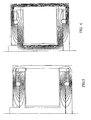
- FIG 4 another example of a vibrator design is illustrated in which the annular permanent magnets 3a, 3b and the coil 1 instead are attached to the casing 4.
- the vibrator force is obtained through the bobbin 2 which is allowed to project out from the casing.
- the two annular permanent magnets 3a, 3b are working independent from each other and are generating a static magnetic field according to figure 5 .
- a dynamic field is generated as illustrated in figure 6 .
- the static and the dynamic magnetic fields are substantially separated from each other, but the fields are coinciding in that part of the vibrator where it is desired with such coinciding fields, i e in the air gaps.
- a third vibrator device which also comprises two permanent magnets like the first examples.
- annular permanent magnets illustrated in the two first embodiments in this case the axially magnetized permanent magnets 3a, 3b are located centrally. They are each arranged in its own centrally located recess in the outer side of the bobbin wall, adjacent to core 2a of the coil and they are disc-shaped (puck-shaped).
- the static and dynamic magnetic fields generated by this third embodiment are illustrated in figures 8 and 9 . Again, it should be clear that the magnetic fields are substantially separated, but they coincide where this is best needed, i. e. in the air gaps. Specifically, the static field only goes through a part of the construction and the dynamic field does not go through the permanent magnets.
- the permanent magnets are axially magnetized.
- FIG 10 there is an example where the permanent magnets 3a, 3b are radially magnetized.
- the magnets are annular and arranged on the end surfaces 8a, 8b of the side walls of the bobbin. Even in this case the static and dynamic fields are separated, as illustrated in figures 11 and 12 . Specifically, the static field does not in any case go through the core 2a of the coil.
- the casing 4 protects the entire construction.
- the vibrator is specifically intended to be used in connection with a bone conduction hearing aid device.
- the casing 4 of the vibrator is resting directly against the skull of the patient.
- bone conduction hearing aid coupling means are arranged on the casing for connection to an implant, for instance a titanium screw, a so-called fixture, anchored in the skull bone.
- an implanted bone conductor the vibrator is used with or without coupling means depending on the implant method.
Abstract
Description
- The present invention relates to a vibrator for hearing aid devices of the bone conduction type, i e hearing aid devices by which the sound information is mechanically transmitted via the skull bone directly to the inner ear of a person with impaired hearing. The vibrator can be used for traditional, bone anchored as well as implanted bone conduction hearing aid devices.
- For persons with impaired hearing, the hearing aid devices which are mainly used today are those based on the principle that the sound is amplified and fed into the auditory meatus and stimulates the eardrum from the outside. In order to prevent feedback problems in these devices, the auditory meatus is almost completely plugged by a hearing plug or by the hearing aid device itself. This causes the user a feeling of pressure, discomfort, and sometimes even eczema. In some cases it even causes the user problems like running ears due to chronic ear inflammations or infections in the auditory canal.
- For persons who cannot benefit from traditional, air conduction hearing aids due to such problems that have been described here it is previously known to use hearing aids which leave the auditory meatus free, see for instance
US 5,411,467 andUS 5,318,502 which hearing aids are both connected to the middle ear. Such a connection, however, requires a surgical operation in the middle ear which is a relatively complicated procedure. - By
US 5,282,858 andUS 4,988,333 it is also previously known to install a part of the hearing aid device on the middle ear bones. Although such a solution leaves the auditory meatus free, it nevertheless requires an extensive surgical installation procedure on the middle ear bones. These types of hearing aids have therefore not been used so much. - However, there are other types of sound transmitting hearing aids on the market, i e bone anchored hearing aids which mechanically transmit the sound information to a persons inner ear via the skull bone by means of a vibrator. The hearing aid device is connected to an implanted titanium screw installed in the bone behind the ear and the sound is transmitted via the skull bone to the cochlea (inner ear), i e the hearing aid works whether there is a disease in the middle ear or not. The bone anchoring principle means that the skin is penetrated which makes the vibratory transmission very efficient.
- This type of hearing aid device has been a revolution for the rehabilitation of patients with certain types of impaired hearing. It is very convenient for the patient and almost invisible with normal hair styles. It can easily be connected to the implanted titanium fixture by means of a bayonet coupling or a snap in coupling. One example of this type of hearing aid device is described in
US Patent No. 4,498,461 and it is also referred to the BAHA® bone anchored hearing aid marketed by Entific Medical Systems in Göteborg. - Even if the bone conduction hearing aid devices have made it possible for more people to benefit from a satisfactory hearing aid, there are also problems with this type of hearing aid devices. One problem is the permanent skin penetration which requires a good hygienic control and has aesthetic limits. By implanting parts of the apparatus hygienic as well as cosmetic aspects can be improved. Such a device is described in
US Patent No. 4,904,233 . A similar implantable bone anchored apparatus is also described in "Hearing by Bone Conduction", Stefan Stenfelt, Chalmers University of Technology, 1999. It is also referred to our co-pending patent applicationPCT/SE01/01229 - A common feature for the hearing aid devices which have been described here is that vibratory generating means, vibrators, are required. Different types of vibrators are well known in the art. There are a number of known vibrator principles today. In traditional as well as in bone anchored hearing aid devices it is normally used a vibrator principle which was described by Bell already in 1876. There is a detailed description of this principle applied on a bone anchored hearing aid device in "On Direct Bone Conduction Hearing Devices", Technical Report No. 195, Department of Applied Electronics, Chalmers University of Technology, 1990.
- It is also referred to Swedish Patent No.
85.02426-3 - In headphones for air conduction hearing aids any type of the so-called "Balanced Armature" principle is often used, see for instance
US Patent No. 905,781, Baldwin 1908 . Even the so-called Moving coil principle, known from conventional loud-speakers, could be used. - Finally, the document
WO0010361 - For vibrators used for bone conduction hearing aid devices there are specific requirements. The vibrators should be powerful enough for transmitting the vibrations to the skull bone and forward the vibrations through the skull bone to the inner ear without any surgical operation in the bone. If a part of the hearing aid device is implantable onto the skull bone the vibrator should be as small and compact as possible.
- The existing vibrator types like Bell, Balanced armature, Floating mass and Moving coil principles can be used also in this type of implantable bone conduction hearing aid devices, but they do not always give an optimal function for this specific application.
- It is an object of the present invention to provide a vibrator device which is powerful enough, but at the same time has a small energy consumption and has small dimensions. The vibrator device is based on the principle that the static and dynamic magnetic fields are separated as far as possible and that the dynamic field does not pass through the permanent magnets in the vibrator.
- The invention is mainly characterized by two permanent magnets which are working independently from each other in a magnetic circuit so that the static and dynamic magnetic fields are substantially separated from each other, whereby the static field is passing through only a part of the vibrator device and provides an axial force.
- According to a preferred embodiment the magnetic circuit is formed as a casing around the vibrator device which casing protects the vibrator and reduces magnetic leakage.
- In the following the invention will be described more in detail with reference to the accompanying drawings, in which
-
figure 1 is a cross-sectional view of a first embodiment of the vibrator, -
figure 2 shows the static magnetic field of the vibrator, -
figure 3 shows the dynamic magnetic field of the vibrator, -
figure 4 shows a second embodiment in which the annular permanent magnets and the coil are attached to the casing, -
figure 5 shows the static magnetic field of this vibrator, -
figure 6 shows the dynamic magnetic field of this vibrator, -
figure 7 shows a third embodiment with axially magnetized disc-shaped magnets, -
figur 8 shows the static magnetic field for this embodiment, -
figur 9 shows the dynamic magnetic field for this embodiment, -
figure 10 shows a fourth embodiment with radially magnetized permanent magnets, -
figure 11 shows the static magnetic field for this fourth embodiment, and -
figure 12 shows the dynamic magnetic field for this fourth embodiment. - As all of the embodiments of the vibrator are rotation symmetrical only one half of each vibrator device is shown in the figures, except from
figure 1. Figure 1 shows a cross-section through the centre axis 1a of a first embodiment of the vibrator. The vibrator comprises a coil 1 which is wound around abobbin base 2 with a core 2a and twoside walls 2c, 2d. In the two side walls there are two outer, peripherally located, annular recesses in which two axially magnetized annular permanent magnets 3a, 3b are attached. The entire coil and magnet arrangement is housed in acasing 4 which forms a part of the magnetic circuit and protects the vibrator and reduces magnetic leakage. The bobbin base and the casing are made of a material with high magnetic conductivity.Inner spring mechanisms air gaps - Instead of mechanically arranged spring mechanisms the vibrator coil could be centered magnetically by means of annular, repelling magnets arranged on the outer side of the bobbin wall and opposite side of the casing.
- The two permanent magnets 3a, 3b are working independent from each other and generates a static magnetic field which is illustrated in
figure 2 . As shown in the figure the magnetic field is passing through only a part of the construction and theair gaps - When an alternating current is passing through the coil 1 a dynamic magnetic field is generated as illustrated in
figure 3 . As shown in the figure a substantial part of the vibrator is passed through only by the dynamic magnetic field, except from the permanent magnets, and as the dynamic magnetic field is small compared to the static field these parts of the vibrator can be made with smaller dimensions (thinner) as the required material thickness is proportional to the strength of the magnetic field. Furthermore these parts can be made of a material which is more suitable for alternating fields. Consequently a substantial part of the vibrator volume can be used for the power generating coil. The power is generated in theair gaps bobbin 2 and the annular magnets 3a, 3b, i e the entire coil and magnet assembly, is moved relative to the casing so that an axial force is obtained as indicated by thearrow 7 infigure 1 . Theinner spring mechanism - By this vibrator design the dynamic and static magnetic fields are substantially separated from each other. However, they are coinciding in that part of the vibrator device where it is desirable for the power generation that the fields are coinciding, i e in the
air gaps - In
figure 4 another example of a vibrator design is illustrated in which the annular permanent magnets 3a, 3b and the coil 1 instead are attached to thecasing 4. The vibrator force is obtained through thebobbin 2 which is allowed to project out from the casing. Similar to the first embodiment the two annular permanent magnets 3a, 3b are working independent from each other and are generating a static magnetic field according tofigure 5 . When an alternating current is passing through the coil 1 a dynamic field is generated as illustrated infigure 6 . The static and the dynamic magnetic fields are substantially separated from each other, but the fields are coinciding in that part of the vibrator where it is desired with such coinciding fields, i e in the air gaps. - It should be understood that there might be hybrids between these two design solutions so that each of the coil and annular magnets are attached to either the bobbin or casing.
- In
figure 7 a third vibrator device is shown which also comprises two permanent magnets like the first examples. In contrast to the peripherally arranged, annular permanent magnets illustrated in the two first embodiments, in this case the axially magnetized permanent magnets 3a, 3b are located centrally. They are each arranged in its own centrally located recess in the outer side of the bobbin wall, adjacent to core 2a of the coil and they are disc-shaped (puck-shaped). - The static and dynamic magnetic fields generated by this third embodiment are illustrated in
figures 8 and 9 . Again, it should be clear that the magnetic fields are substantially separated, but they coincide where this is best needed, i. e. in the air gaps. Specifically, the static field only goes through a part of the construction and the dynamic field does not go through the permanent magnets. - In the embodiments which have been illustrated so far the permanent magnets are axially magnetized. In
figure 10 there is an example where the permanent magnets 3a, 3b are radially magnetized. The magnets are annular and arranged on the end surfaces 8a, 8b of the side walls of the bobbin. Even in this case the static and dynamic fields are separated, as illustrated infigures 11 and 12 . Specifically, the static field does not in any case go through the core 2a of the coil. Thecasing 4 protects the entire construction. - As mentioned by way of introduction the vibrator is specifically intended to be used in connection with a bone conduction hearing aid device. In case of conventional bone conduction the
casing 4 of the vibrator is resting directly against the skull of the patient. In case of a bone anchored, bone conduction hearing aid coupling means are arranged on the casing for connection to an implant, for instance a titanium screw, a so-called fixture, anchored in the skull bone. In case of an implanted bone conductor the vibrator is used with or without coupling means depending on the implant method. - The invention is not limited to the embodiments illustrated in the figures but can be varied within the scope of the accompanying claims. Specifically it should be understood that there could be hybrids between the different embodiments.
Claims (18)
- Vibrator for hearing aid devices of the bone conduction type, i e hearing aid devices by which the sound information is mechanically transmitted via the skull bone directly to the inner ear of a person with impaired hearing, said vibrator comprising a coil (1) for generating a dynamic magnetic field and permanent magnet means (3a, 3b) for generating a static magnetic field in a magnetic circuit
characterized in that the permanent magnet means comprises two permanent magnets (3a, 3b) which are working independently from each other in the magnetic circuit and arranged in such a way that the static and dynamic magnetic fields are substantially separated from each other, whereby the static field is passing through only a part of the magnetic circuit and whereby the vibrator provides an axial force (7). - Vibrator according to claim 1 characterized in that the entire coil and magnet arrangement is enclosed in a casing (4) which forms a part of the magnetic circuit and protects the vibrator and reduces magnetic leakage.
- Vibrator according to claim 2 characterized in that the static and dynamic magnetic fields are coinciding in the air gaps (6a, 6b) formed between the coil and magnet arrangement and the casing (4).
- vibrator according to claim 3 characterized in that inner spring means (5a, 5b) are arranged between the coil and magnet arrangement and the casing (4) so that the coil and magnet arrangement in its rest position is centered in the casing (4) between two air gaps (6a, 6b) of the same size.
- Vibrator according to claim 3 characterized in that repellent magnets are arranged in the coil and magnet arrangement and in opposite parts of the casing (4) so that the coil and magnet arrangement in its rest position is centered in the casing (4) between two air gaps (6a, 6b) of the same size.
- vibrator according to claim 3 characterized in that the vibrator is filled with a liquid in order to damp the vibratory movements of the coil and magnet arrangement.
- Vibrator according to claim 1 characterized in that the coil (1) is wound around a bobbin base (2) with a core (2a) and two side walls (2c, 2d) with two outer recesses in which the two permanent magnets (3a, 3b) are attached.
- Vibrator according to claim 7 characterized in that the permanent magnets (3a, 3b) are axially magnetized.
- Vibrator according to claim 7 characterized in that the two recesses are annular and arranged peripherally for attachment of two annular permanent magnets (3a, 3b).
- Vibrator according to claim 7 characterized in that the two recesses are located centrally for attachment of two disc shaped permanent magnets (3a, 3b).
- Vibrator according to claim 1 characterized in that the coil (1) and permanent magnets (3a, 3b) are attached to the casing (4) in which case the axial force (7) from the vibrator is obtained through the coil bobbin (2) which is protruding the casing (4).
- Vibrator according to claim 1 characterized in that the coil (1) is wound around a bobbin base (2) with a core (2a) and two side walls (2c, 2d) in which case the two permanent magnets (3a, 3b) are arranged on the end surfaces (8a, 8b) of the side walls.
- Vibrator according to claim 12 characterized in that the permanent magnets (3a, 3b) are annular and radially magnetized.
- Vibrator according to claim 1 characterized in that the magnetic circuit is arranged in such a way that the static magnetic field does not pass through core (2a) of the coil and that the dynamic magnetic field does not pass through the permanent magnets (3a, 3b).
- Vibrator according to claim 1 characterized in that the vibrator is included in a bone conduction hearing aid device of the type which comprises an external part with a microphone and electronic circuitry and an internal, implantable part to be anchored subcutaneously onto the skull bone and in which case the vibrator is arranged in the implantable part.
- Vibrator according to claim 15 characterized in that the required energy for the vibrator is provided by means of induction.
- vibrator according to claim 15 characterized in that the required energy for the vibrator is provided by means of a rechargeable battery arranged in the implantable part of the vibrator.
- Vibrator according to claim 15 characterized in that the vibrator is directly connected to an osseointegrating part of the implantable part.
Applications Claiming Priority (3)
| Application Number | Priority Date | Filing Date | Title |
|---|---|---|---|
| SE0002073 | 2000-06-02 | ||
| SE0002073A SE0002073L (en) | 2000-06-02 | 2000-06-02 | Vibrator for leg anchored and leg conduit hearing aids |
| PCT/SE2001/001227 WO2001093633A1 (en) | 2000-06-02 | 2001-05-31 | Vibrator for boneconducted hearing aids |
Publications (2)
| Publication Number | Publication Date |
|---|---|
| EP1305979A1 EP1305979A1 (en) | 2003-05-02 |
| EP1305979B1 true EP1305979B1 (en) | 2009-01-14 |
Family
ID=20279950
Family Applications (1)
| Application Number | Title | Priority Date | Filing Date |
|---|---|---|---|
| EP01937100A Expired - Lifetime EP1305979B1 (en) | 2000-06-02 | 2001-05-31 | Vibrator for boneconducted hearing aids |
Country Status (8)
| Country | Link |
|---|---|
| US (1) | US7319771B2 (en) |
| EP (1) | EP1305979B1 (en) |
| AT (1) | ATE421229T1 (en) |
| AU (1) | AU2001262865A1 (en) |
| DE (1) | DE60137429D1 (en) |
| DK (1) | DK1305979T3 (en) |
| SE (1) | SE0002073L (en) |
| WO (1) | WO2001093633A1 (en) |
Families Citing this family (25)
| Publication number | Priority date | Publication date | Assignee | Title |
|---|---|---|---|---|
| SE516270C2 (en) * | 2000-03-09 | 2001-12-10 | Osseofon Ab | Electromagnetic vibrator |
| US7471801B2 (en) | 2002-05-10 | 2008-12-30 | Osseofon Ab | Device for the generation of or monitoring of vibrations |
| SE522164C2 (en) * | 2002-05-10 | 2004-01-20 | Osseofon Ab | Device for electromagnetic vibrator |
| SE525631C2 (en) * | 2003-09-19 | 2005-03-22 | P & B Res Ab | Method and apparatus for attenuating resonant frequency |
| US7376237B2 (en) * | 2004-09-02 | 2008-05-20 | Oticon A/S | Vibrator for bone-conduction hearing |
| SE528279C2 (en) | 2005-02-21 | 2006-10-10 | Entific Medical Systems Ab | Vibrator for bone conductive hearing aid |
| US8246532B2 (en) | 2006-02-14 | 2012-08-21 | Vibrant Med-El Hearing Technology Gmbh | Bone conductive devices for improving hearing |
| SE0600843L (en) | 2006-04-12 | 2007-10-13 | Osseofon Ab | Method of manufacturing balanced vibrator |
| SE0701242L (en) | 2007-05-24 | 2008-12-02 | Cochlear Ltd | Vibrator |
| EP2254345A4 (en) * | 2008-03-17 | 2012-08-29 | Temco Japan | Bone conduction speaker and listening device using same |
| US8852251B2 (en) | 2008-03-31 | 2014-10-07 | Cochlear Limited | Mechanical fixation system for a prosthetic device |
| US8144909B2 (en) * | 2008-08-12 | 2012-03-27 | Cochlear Limited | Customization of bone conduction hearing devices |
| DE102009014774A1 (en) | 2009-03-25 | 2010-09-30 | Cochlear Ltd., Lane Cove | hearing aid |
| USRE48797E1 (en) | 2009-03-25 | 2021-10-26 | Cochlear Limited | Bone conduction device having a multilayer piezoelectric element |
| DE102009014770A1 (en) | 2009-03-25 | 2010-09-30 | Cochlear Ltd., Lane Cove | vibrator |
| SE1000876A1 (en) * | 2010-08-28 | 2011-12-27 | Osseofon Ab | Miniature variable reluctance vibrator |
| US8565461B2 (en) * | 2011-03-16 | 2013-10-22 | Cochlear Limited | Bone conduction device including a balanced electromagnetic actuator having radial and axial air gaps |
| CN103503484B (en) | 2011-03-23 | 2017-07-21 | 耳蜗有限公司 | The allotment of hearing device |
| US9107013B2 (en) | 2011-04-01 | 2015-08-11 | Cochlear Limited | Hearing prosthesis with a piezoelectric actuator |
| JP5591314B2 (en) * | 2012-12-18 | 2014-09-17 | 京セラ株式会社 | Electronic device with bone conduction vibration element |
| US9432782B2 (en) * | 2013-03-14 | 2016-08-30 | Cochlear Limited | Electromagnetic transducer with air gap substitute |
| US9716953B2 (en) | 2013-03-15 | 2017-07-25 | Cochlear Limited | Electromagnetic transducer with specific internal geometry |
| AT516871B1 (en) * | 2015-03-05 | 2018-03-15 | Bhm Tech Produktionsgesellschaft M B H | Electromagnetic transducer for a bone conduction listener |
| US11778385B2 (en) | 2017-06-23 | 2023-10-03 | Cochlear Limited | Electromagnetic transducer with non-axial air gap |
| US11035830B2 (en) | 2017-06-23 | 2021-06-15 | Cochlear Limited | Electromagnetic transducer with dual flux |
Family Cites Families (23)
| Publication number | Priority date | Publication date | Assignee | Title |
|---|---|---|---|---|
| US905781A (en) | 1908-01-29 | 1908-12-01 | William Witt | Telephone-receiver. |
| US2500541A (en) * | 1945-07-18 | 1950-03-14 | Emil H Greibach | Inertia-type electromechanical sound transducing device |
| SE431705B (en) | 1981-12-01 | 1984-02-20 | Bo Hakansson | COUPLING, PREFERRED FOR MECHANICAL TRANSMISSION OF SOUND INFORMATION TO THE BALL OF A HEARING DAMAGED PERSON |
| SE447947B (en) | 1985-05-10 | 1986-12-22 | Bo Hakansson | DEVICE FOR A HORSE DEVICE |
| SE447948B (en) | 1985-05-15 | 1986-12-22 | Bo Hakansson | Vibrator for hearing aid |
| US4606329A (en) | 1985-05-22 | 1986-08-19 | Xomed, Inc. | Implantable electromagnetic middle-ear bone-conduction hearing aid device |
| US4988333A (en) | 1988-09-09 | 1991-01-29 | Storz Instrument Company | Implantable middle ear hearing aid system and acoustic coupler therefor |
| DE3918086C1 (en) | 1989-06-02 | 1990-09-27 | Hortmann Gmbh, 7449 Neckartenzlingen, De | |
| US5176620A (en) | 1990-10-17 | 1993-01-05 | Samuel Gilman | Hearing aid having a liquid transmission means communicative with the cochlea and method of use thereof |
| US5282858A (en) | 1991-06-17 | 1994-02-01 | American Cyanamid Company | Hermetically sealed implantable transducer |
| SE9301406D0 (en) | 1993-04-27 | 1993-04-27 | Medevelop Ab | FOE IMPLANTATION IN THE WEBSITE PROVIDED FOR THE HALLAR ORGAN FOR CONTROLLED RECORDING AND LOCATION FIXING OF WIRELESS WIRES FOR ELECTRIC INFORMATION TRANSFER USEFUL EQUIPMENT AND SET FOR ITS APPLICATION |
| US5897486A (en) | 1993-07-01 | 1999-04-27 | Symphonix Devices, Inc. | Dual coil floating mass transducers |
| US5913815A (en) | 1993-07-01 | 1999-06-22 | Symphonix Devices, Inc. | Bone conducting floating mass transducers |
| US5800336A (en) * | 1993-07-01 | 1998-09-01 | Symphonix Devices, Inc. | Advanced designs of floating mass transducers |
| US5615229A (en) | 1993-07-02 | 1997-03-25 | Phonic Ear, Incorporated | Short range inductively coupled communication system employing time variant modulation |
| NZ316550A (en) * | 1995-09-02 | 1998-10-28 | New Transducers Ltd | Vibration transducers |
| SE507336C2 (en) | 1995-10-12 | 1998-05-18 | Nobel Biocare Ab | Holder for bone implantation |
| US5951601A (en) | 1996-03-25 | 1999-09-14 | Lesinski; S. George | Attaching an implantable hearing aid microactuator |
| JPH1157066A (en) * | 1997-08-19 | 1999-03-02 | Bridgestone Sports Co Ltd | Golf ball |
| KR19980063410A (en) | 1997-08-19 | 1998-10-07 | 양승택 | Telephone with handcuffs for both bone and airway hearing |
| US6217508B1 (en) | 1998-08-14 | 2001-04-17 | Symphonix Devices, Inc. | Ultrasonic hearing system |
| SE516270C2 (en) | 2000-03-09 | 2001-12-10 | Osseofon Ab | Electromagnetic vibrator |
| SE523123C2 (en) | 2000-06-02 | 2004-03-30 | P & B Res Ab | Hearing aid that works with the principle of bone conduction |
-
2000
- 2000-06-02 SE SE0002073A patent/SE0002073L/en not_active IP Right Cessation
-
2001
- 2001-05-31 EP EP01937100A patent/EP1305979B1/en not_active Expired - Lifetime
- 2001-05-31 AU AU2001262865A patent/AU2001262865A1/en not_active Abandoned
- 2001-05-31 US US10/296,977 patent/US7319771B2/en not_active Expired - Fee Related
- 2001-05-31 WO PCT/SE2001/001227 patent/WO2001093633A1/en active Application Filing
- 2001-05-31 DK DK01937100T patent/DK1305979T3/en active
- 2001-05-31 DE DE60137429T patent/DE60137429D1/en not_active Expired - Lifetime
- 2001-05-31 AT AT01937100T patent/ATE421229T1/en active
Also Published As
| Publication number | Publication date |
|---|---|
| US7319771B2 (en) | 2008-01-15 |
| DE60137429D1 (en) | 2009-03-05 |
| US20040028249A1 (en) | 2004-02-12 |
| AU2001262865A1 (en) | 2001-12-11 |
| WO2001093633A1 (en) | 2001-12-06 |
| SE514929C2 (en) | 2001-05-21 |
| DK1305979T3 (en) | 2009-03-23 |
| SE0002073L (en) | 2001-05-21 |
| EP1305979A1 (en) | 2003-05-02 |
| SE0002073D0 (en) | 2000-06-02 |
| ATE421229T1 (en) | 2009-01-15 |
Similar Documents
| Publication | Publication Date | Title |
|---|---|---|
| EP1305978B1 (en) | Vibrator for bone conducted hearing aids | |
| EP1305979B1 (en) | Vibrator for boneconducted hearing aids | |
| EP1882386B1 (en) | Vibrator | |
| US11910165B2 (en) | Removable attachment of a passive transcutaneous bone conduction device with limited skin deformation | |
| US20040032962A1 (en) | Bone conducting hearing aid | |
| US6735318B2 (en) | Middle ear hearing aid transducer | |
| EP2538700B1 (en) | Skull vibration unit | |
| US6084975A (en) | Promontory transmitting coil and tympanic membrane magnet for hearing devices | |
| US7442164B2 (en) | Totally implantable hearing prosthesis | |
| EP1457090B1 (en) | Vibrator damping | |
| WO2003001846A1 (en) | Hearing aid apparatus | |
| US8620015B2 (en) | Vibrator for bone conducting hearing devices | |
| EP1671514B1 (en) | A method and an arrangement for damping a resonance frequency | |
| Taghavi | A novel bone conduction implant system |
Legal Events
| Date | Code | Title | Description |
|---|---|---|---|
| PUAI | Public reference made under article 153(3) epc to a published international application that has entered the european phase |
Free format text: ORIGINAL CODE: 0009012 |
|
| 17P | Request for examination filed |
Effective date: 20021219 |
|
| AK | Designated contracting states |
Designated state(s): AT BE CH CY DE DK ES FI FR GB GR IE IT LI LU MC NL PT SE TR |
|
| AX | Request for extension of the european patent |
Extension state: AL LT LV MK RO SI |
|
| GRAP | Despatch of communication of intention to grant a patent |
Free format text: ORIGINAL CODE: EPIDOSNIGR1 |
|
| RIC1 | Information provided on ipc code assigned before grant |
Ipc: H04R 9/02 20060101ALN20080716BHEP Ipc: H04R 9/00 20060101ALN20080716BHEP Ipc: H04R 25/00 20060101AFI20080716BHEP Ipc: H04R 25/02 20060101ALN20080716BHEP |
|
| GRAS | Grant fee paid |
Free format text: ORIGINAL CODE: EPIDOSNIGR3 |
|
| GRAS | Grant fee paid |
Free format text: ORIGINAL CODE: EPIDOSNIGR3 |
|
| GRAA | (expected) grant |
Free format text: ORIGINAL CODE: 0009210 |
|
| AK | Designated contracting states |
Kind code of ref document: B1 Designated state(s): AT BE CH CY DE DK ES FI FR GB GR IE IT LI LU MC NL PT SE TR |
|
| REG | Reference to a national code |
Ref country code: GB Ref legal event code: FG4D |
|
| REG | Reference to a national code |
Ref country code: CH Ref legal event code: EP |
|
| REG | Reference to a national code |
Ref country code: IE Ref legal event code: FG4D |
|
| REF | Corresponds to: |
Ref document number: 60137429 Country of ref document: DE Date of ref document: 20090305 Kind code of ref document: P |
|
| REG | Reference to a national code |
Ref country code: CH Ref legal event code: NV Representative=s name: E. BLUM & CO. AG PATENT- UND MARKENANWAELTE VSP |
|
| REG | Reference to a national code |
Ref country code: DK Ref legal event code: T3 |
|
| PG25 | Lapsed in a contracting state [announced via postgrant information from national office to epo] |
Ref country code: NL Free format text: LAPSE BECAUSE OF FAILURE TO SUBMIT A TRANSLATION OF THE DESCRIPTION OR TO PAY THE FEE WITHIN THE PRESCRIBED TIME-LIMIT Effective date: 20090114 |
|
| REG | Reference to a national code |
Ref country code: CH Ref legal event code: PUE Owner name: OSSEOFON AB Free format text: P & B RESEARCH AB#SPLINTVEDSGATAN 7#416 80 GOETEBORG (SE) -TRANSFER TO- OSSEOFON AB#SPLINTVEDSGATAN 7#41680 GOETEBORG (SE) |
|
| NLV1 | Nl: lapsed or annulled due to failure to fulfill the requirements of art. 29p and 29m of the patents act | ||
| REG | Reference to a national code |
Ref country code: FR Ref legal event code: TP |
|
| REG | Reference to a national code |
Ref country code: GB Ref legal event code: 732E Free format text: REGISTERED BETWEEN 20090702 AND 20090708 |
|
| PG25 | Lapsed in a contracting state [announced via postgrant information from national office to epo] |
Ref country code: ES Free format text: LAPSE BECAUSE OF FAILURE TO SUBMIT A TRANSLATION OF THE DESCRIPTION OR TO PAY THE FEE WITHIN THE PRESCRIBED TIME-LIMIT Effective date: 20090425 Ref country code: FI Free format text: LAPSE BECAUSE OF FAILURE TO SUBMIT A TRANSLATION OF THE DESCRIPTION OR TO PAY THE FEE WITHIN THE PRESCRIBED TIME-LIMIT Effective date: 20090114 |
|
| PG25 | Lapsed in a contracting state [announced via postgrant information from national office to epo] |
Ref country code: PT Free format text: LAPSE BECAUSE OF FAILURE TO SUBMIT A TRANSLATION OF THE DESCRIPTION OR TO PAY THE FEE WITHIN THE PRESCRIBED TIME-LIMIT Effective date: 20090615 Ref country code: SE Free format text: LAPSE BECAUSE OF FAILURE TO SUBMIT A TRANSLATION OF THE DESCRIPTION OR TO PAY THE FEE WITHIN THE PRESCRIBED TIME-LIMIT Effective date: 20090414 |
|
| PG25 | Lapsed in a contracting state [announced via postgrant information from national office to epo] |
Ref country code: BE Free format text: LAPSE BECAUSE OF FAILURE TO SUBMIT A TRANSLATION OF THE DESCRIPTION OR TO PAY THE FEE WITHIN THE PRESCRIBED TIME-LIMIT Effective date: 20090114 |
|
| PLBE | No opposition filed within time limit |
Free format text: ORIGINAL CODE: 0009261 |
|
| STAA | Information on the status of an ep patent application or granted ep patent |
Free format text: STATUS: NO OPPOSITION FILED WITHIN TIME LIMIT |
|
| 26N | No opposition filed |
Effective date: 20091015 |
|
| PG25 | Lapsed in a contracting state [announced via postgrant information from national office to epo] |
Ref country code: MC Free format text: LAPSE BECAUSE OF NON-PAYMENT OF DUE FEES Effective date: 20090531 |
|
| REG | Reference to a national code |
Ref country code: CH Ref legal event code: PL |
|
| PG25 | Lapsed in a contracting state [announced via postgrant information from national office to epo] |
Ref country code: LI Free format text: LAPSE BECAUSE OF NON-PAYMENT OF DUE FEES Effective date: 20090531 Ref country code: CH Free format text: LAPSE BECAUSE OF NON-PAYMENT OF DUE FEES Effective date: 20090531 |
|
| PGFP | Annual fee paid to national office [announced via postgrant information from national office to epo] |
Ref country code: DK Payment date: 20091110 Year of fee payment: 9 |
|
| REG | Reference to a national code |
Ref country code: IE Ref legal event code: MM4A |
|
| PG25 | Lapsed in a contracting state [announced via postgrant information from national office to epo] |
Ref country code: IE Free format text: LAPSE BECAUSE OF NON-PAYMENT OF DUE FEES Effective date: 20090531 |
|
| PGFP | Annual fee paid to national office [announced via postgrant information from national office to epo] |
Ref country code: GB Payment date: 20091111 Year of fee payment: 9 |
|
| PG25 | Lapsed in a contracting state [announced via postgrant information from national office to epo] |
Ref country code: GR Free format text: LAPSE BECAUSE OF FAILURE TO SUBMIT A TRANSLATION OF THE DESCRIPTION OR TO PAY THE FEE WITHIN THE PRESCRIBED TIME-LIMIT Effective date: 20090415 |
|
| REG | Reference to a national code |
Ref country code: DK Ref legal event code: EBP |
|
| GBPC | Gb: european patent ceased through non-payment of renewal fee |
Effective date: 20100531 |
|
| PG25 | Lapsed in a contracting state [announced via postgrant information from national office to epo] |
Ref country code: IT Free format text: LAPSE BECAUSE OF FAILURE TO SUBMIT A TRANSLATION OF THE DESCRIPTION OR TO PAY THE FEE WITHIN THE PRESCRIBED TIME-LIMIT Effective date: 20090114 |
|
| PG25 | Lapsed in a contracting state [announced via postgrant information from national office to epo] |
Ref country code: LU Free format text: LAPSE BECAUSE OF NON-PAYMENT OF DUE FEES Effective date: 20090531 Ref country code: DK Free format text: LAPSE BECAUSE OF NON-PAYMENT OF DUE FEES Effective date: 20100531 |
|
| PG25 | Lapsed in a contracting state [announced via postgrant information from national office to epo] |
Ref country code: GB Free format text: LAPSE BECAUSE OF NON-PAYMENT OF DUE FEES Effective date: 20100531 |
|
| PG25 | Lapsed in a contracting state [announced via postgrant information from national office to epo] |
Ref country code: TR Free format text: LAPSE BECAUSE OF FAILURE TO SUBMIT A TRANSLATION OF THE DESCRIPTION OR TO PAY THE FEE WITHIN THE PRESCRIBED TIME-LIMIT Effective date: 20090114 |
|
| PG25 | Lapsed in a contracting state [announced via postgrant information from national office to epo] |
Ref country code: CY Free format text: LAPSE BECAUSE OF FAILURE TO SUBMIT A TRANSLATION OF THE DESCRIPTION OR TO PAY THE FEE WITHIN THE PRESCRIBED TIME-LIMIT Effective date: 20090114 |
|
| REG | Reference to a national code |
Ref country code: FR Ref legal event code: PLFP Year of fee payment: 16 |
|
| REG | Reference to a national code |
Ref country code: FR Ref legal event code: PLFP Year of fee payment: 17 |
|
| REG | Reference to a national code |
Ref country code: FR Ref legal event code: PLFP Year of fee payment: 18 |
|
| PGFP | Annual fee paid to national office [announced via postgrant information from national office to epo] |
Ref country code: DE Payment date: 20200507 Year of fee payment: 20 Ref country code: FR Payment date: 20200512 Year of fee payment: 20 |
|
| PGFP | Annual fee paid to national office [announced via postgrant information from national office to epo] |
Ref country code: AT Payment date: 20200507 Year of fee payment: 20 |
|
| REG | Reference to a national code |
Ref country code: DE Ref legal event code: R071 Ref document number: 60137429 Country of ref document: DE |
|
| REG | Reference to a national code |
Ref country code: AT Ref legal event code: MK07 Ref document number: 421229 Country of ref document: AT Kind code of ref document: T Effective date: 20210531 |