EP1305535B1 - Hydrodynamic brake - Google Patents
Hydrodynamic brake Download PDFInfo
- Publication number
- EP1305535B1 EP1305535B1 EP01944087A EP01944087A EP1305535B1 EP 1305535 B1 EP1305535 B1 EP 1305535B1 EP 01944087 A EP01944087 A EP 01944087A EP 01944087 A EP01944087 A EP 01944087A EP 1305535 B1 EP1305535 B1 EP 1305535B1
- Authority
- EP
- European Patent Office
- Prior art keywords
- rotor
- edge surface
- vanes
- stator
- extension
- Prior art date
- Legal status (The legal status is an assumption and is not a legal conclusion. Google has not performed a legal analysis and makes no representation as to the accuracy of the status listed.)
- Expired - Lifetime
Links
- 239000003921 oil Substances 0.000 description 22
- 238000010276 construction Methods 0.000 description 3
- 239000010724 circulating oil Substances 0.000 description 2
- 230000003247 decreasing effect Effects 0.000 description 2
- 238000000034 method Methods 0.000 description 2
- 230000005540 biological transmission Effects 0.000 description 1
- 230000015572 biosynthetic process Effects 0.000 description 1
- 239000002826 coolant Substances 0.000 description 1
- 230000000694 effects Effects 0.000 description 1
- 230000003628 erosive effect Effects 0.000 description 1
- 238000004519 manufacturing process Methods 0.000 description 1
- 230000010355 oscillation Effects 0.000 description 1
- 230000003405 preventing effect Effects 0.000 description 1
- 238000005303 weighing Methods 0.000 description 1
Images


Classifications
-
- F—MECHANICAL ENGINEERING; LIGHTING; HEATING; WEAPONS; BLASTING
- F16—ENGINEERING ELEMENTS AND UNITS; GENERAL MEASURES FOR PRODUCING AND MAINTAINING EFFECTIVE FUNCTIONING OF MACHINES OR INSTALLATIONS; THERMAL INSULATION IN GENERAL
- F16D—COUPLINGS FOR TRANSMITTING ROTATION; CLUTCHES; BRAKES
- F16D57/00—Liquid-resistance brakes; Brakes using the internal friction of fluids or fluid-like media, e.g. powders
- F16D57/005—Details of blades, e.g. shape
-
- F—MECHANICAL ENGINEERING; LIGHTING; HEATING; WEAPONS; BLASTING
- F16—ENGINEERING ELEMENTS AND UNITS; GENERAL MEASURES FOR PRODUCING AND MAINTAINING EFFECTIVE FUNCTIONING OF MACHINES OR INSTALLATIONS; THERMAL INSULATION IN GENERAL
- F16D—COUPLINGS FOR TRANSMITTING ROTATION; CLUTCHES; BRAKES
- F16D57/00—Liquid-resistance brakes; Brakes using the internal friction of fluids or fluid-like media, e.g. powders
- F16D57/04—Liquid-resistance brakes; Brakes using the internal friction of fluids or fluid-like media, e.g. powders with blades causing a directed flow, e.g. Föttinger type
Definitions
- the present invention relates to a hydrodynamic brake according to the preamble of claim 1.
- a hydrodynamic brake is for instance disclosed in US-A-3 761 196.
- the retarder In connection with the use of hydrodynamic brakes, such as retarders in vehicles, it is an ambition to reduce the volume of sound generated by the retarder and to increase the braking capacity of the retarder such that it may be made smaller with a maintained capacity.
- the retarder has such a construction that cavitation of the medium is avoided when it flows with a high velocity in the toroid-shaped space of the retarder.
- the medium is usually an oil having suitable properties for such a flow.
- the cavitation of the medium arises when the pressure is below the boiler pressure of the medium such that the medium locally transforms into vapour phase and forms gas bubbles. When the pressure again arises over the boiler pressure level, the medium condenses and the gas bubbles collapse with heavy pressure shots as a consequence.
- the object of the present invention is to provide a hydrodynamic brake which has such a construction that cavitation of the medium as far as possible is avoided for reducing the risk of sonic booms, for avoiding mechanical wear damages on the vanes and for providing a brake with a reliable high performance.
- the hydrodynamic brake of the initially mentioned kind which is characterised by the features mentioned in the characterising part of claim 1.
- the wall surfaces of a vane of a conventional stator where the lowest pressures arises is in an area at the radial outer end of the edge surface. In this area, there is above all such a risk for cavitation that the medium locally is vaporised. Since the vane according to the present invention lacks wall surfaces in this sensitive area, the same low pressures do not arise here as at conventional vanes. Thus, the cavitation of the medium is prevented in a simple and effective way. Mechanical damages on the vanes caused by cavitation are avoided as well as sonic booms such that the hydrodynamic brake does not generate an unnecessarily high sound level. Thus, the hydrodynamic brake may be given a high and reliable performance.
- the outer end of the edge surface of the vane is located at a distance inside said straight line, which distance has a value within an interval of 10 to 30 % of the radius of the toroid-shaped space.
- the outer end of the edge surface of the vane ought at least to be located at a distance, with a value of at least 10 % of the radius of the toroid-shaped space, from said line in order to prevent cavitation to arise in the area.
- the distance should not exceed 30 % of the radius of the toroid-shaped space. If said distance becomes greater than 30 % of the radius of the toroid-shaped space, the vane capacity is decreased so much that it is not compensated for a cavitation free operation.
- An optimal distance between the outer end of the edge surface of the vane and said line is within an interval of between 15-25% of the radius of the toroid-shaped space.
- said free edge surface of the vane has a chamfered portion, which comprises said outer end and has an extension at which the distance to said line increases continuously from a brake-point to said outer end.
- the edge surface obtains a shape which does not appreciable influence on the capacity of the hydrodynamic brake.
- the brake-point on the edge surface is with advantage provided at a distance of between 25 and 75 % of the radius of the toroid-shaped space from the outer end.
- said first portion of the edge surface has a linear extension from the brake-point to the outer end.
- the free edge surface comprises a second portion, which extends between a radially inner end of the edge surface to said brake-point, and the second portion of the edge surface has an extension which coincides with the extension of said line.
- This second portion thus obtains in this area a corresponding extension as the edge surface of a conventional stator vane.
- the edge surface of at least one of the vanes of the rotor has a radially inner end located on the inside of a straight line extending between the inner and outer edges, which restricts the recess of the rotor.
- the risk of cavitation in this area is not as great as at the outer ends of the stator vanes but this risk is not negligible.
- the vane of the rotor according to the invention consequently lacks the part of a conventional vane of a rotor where such low pressures may arise so that the medium is vaporised. Thereby, it is also here in a simple and effective manner prevented that mechanical damages arise in this area at the same time as sonic booms are avoided.
- the inner end of the free edge surface of the vane of the rotor is located at a distance inside said straight line restricting the recess of the rotor, which distance is within an interval comprising 10-30 % of the radius of the toroid-shaped space.
- An optimal value of the distance from said line is also here within the interval 15-25 % of the radius of the toroid-shaped space.
- the free edge surface of the rotor vane has a chamfered portion, which is located on the inside of said straight line which restricts the recess of the rotor and which has an extension at which the distance to said line increases continuously from the brake-point to the inner end.
- the chamfered portion of the edge surface has a linear extension from the brake-point to the inner end.
- the free edge surface of the vane of the rotor comprises a second portion, which extends between a radially outer end of the edge surface to said brake-point, and the second portion of the edge surface has an extension which coincides with the extension of said line.
- the second portion obtains an unchanged extension in relation to a conventional rotor vane.
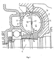
- Fig 1 shows a cross-section through a portion of a hydrodynamic brake in form of a retarder of a motor driven vehicle.
- the retarder comprises a stator 1 and a rotor 2.
- the stator 1 which is shown separately in Fig 2, comprises an inner radial surface 3, which defines a circular opening.
- a rotatable shaft 4 is arranged to extend through the circular opening of the stator 1.
- the rotatable shaft 4 is, via a transmission device, in connection with a driving shaft of the vehicle.
- the stator 1 is fixedly provided in the vehicle in a suitable manner.
- the stator 1, which is shown separately in Fig 2, comprises an annular recess 5, which in the mounted state of the retarder, extends around the rotatable shaft 4.
- the annular recess 5 is restricted in a radial direction outwards by an outer edge 6 and in a radial direction inwards by an inner edge 7.
- a plurality of vanes 8 are provided with uniform intervals along the circular extension of the annular recess 5.
- the vanes 8 comprise an edge surface 9 fixedly provided to the bottom surface of the recess 5 and a free edge surface 10 which is not in contact with the bottom surface of the recess 5.
- the free edge surface 10 has a substantially radial extension through the recess 5 from its inner edge 7 in a direction towards its outer edge 6.
- Each of the fixedly provided edge surfaces 9 of vanes 8 and the free edge surfaces 10 of the vanes 8 are displaced in relation to each other in the recess 5 such that the lateral surfaces of the vanes obtain an angle of about 45° in relation to the bottom surface of the recess 5.
- the rotor 2 which is shown separately in Fig 3, comprises a body with a shaft portion 11 fixedly connected to the rotatable shaft 4. Thus, the rotor 2 will rotate synchronously with the rotatable shaft 4.
- the rotor 2 comprises moreover a substantially corresponding construction as the stator 1 and comprises an annular recess 12, which in the mounted state of the rotor 2, extends around the rotatable shaft 4.
- the annular recess 12 is restricted in a radial direction outwards by an outer edge 13 and in a radial direction inwards by an inner edge 14.
- a plurality of vanes 15 are provided with uniform intervals along the circular extension of the annular recess 12.
- the vanes 15 comprise an edge surface 16 fixedly provided to the bottom surface of the recess 12 and a free edge surface, which is not in contact with the bottom surface of the recess 12.
- the free edge surface 17 has a substantially radial extension through the recess 12 from its radially outer edge 13 in a direction towards its radially inner edge 14.
- Each of the fixedly provided edge surfaces 16 and the free edge surfaces 17 of the vanes 15 are displaced in relation to each other in the recess 12 in such a way that the lateral surfaces of the vanes 15 obtain an angle of about 45° in relation to the bottom surface in the recess 12.
- the stator 1 and the rotor 2 are provided coaxially in relation to each other around the shaft 4 such that the annular recesses 5, 12 of the stator 1 and the rotor 2 together forms a toroid-shaped space, which extends around the rotatable shaft 4.
- the stator 1 comprises a plurality of openings 18 through which a medium in form of an oil is introduceable to the toroid-shaped space when the vehicle is intended to be braked.
- the supplied oil is guided, during the rotation of the rotor 2, radially outwards by the vanes 15 in the toroid-shaped space along the bottom surface of the rotor recess 12 and is thrown with a high velocity from the outer edge 13 of the rotor recess over to the outer edge 6 of the stator recess 5.
- the direction of rotation of the oil in the toroid-shaped space is shown by the arrows A in the figures 1 and 4.
- the oil hits the vanes 8 of the stator 1 and the motion of the oil in the direction of rotation of the rotor 2 is retarded and the oil is guided by the vanes 8 radially inwards along the bottom surface of the recess 5 until it reaches the inner edge 7 of the recess 5.
- the oil again is thrown over to the rotor 2 and hits the rotor 2 at the inner edge surface 14 of the recess 12.
- the oil hits the rotating vanes 15 of the rotor 2 at such an angle that a substantially optimal brake action of the rotor 2 is obtained.
- the brake action which is obtained by the rotor 2, depends partly on the quantity of oil which is supplied and is circulated in the toroid-shaped space and partly on the rotation speed of the rotor 2. During the braking process, the kinetic energy of the oil is transformed to heat energy.
- the stator 1 comprises a number of openings 19 through which the oil is arranged to be removed from the toroid-shaped space.
- the quantity of oil, which flows in the toroid-shaped space between the inlet openings 18 and the outlet openings 19, may be up to 400 l/min.
- the oil After the circulating oil has left the retarder, it is cooled before it again is supplied to the toroid-shaped space.
- the oil also works as an effective cooling medium, which removes the heat energy, generated during the braking process, from the retarder.
- the vanes 8 of the stator 2 here comprise a chamfered portion 20, see Fig 4.
- the chamfered portion 20 is located in the recess 5 on the inside of a straight line I 1 , which extends between the outer 6 and the inner 7 edges, which restricts the recess 5 of the stator 1.
- the chamfered portion 20 has a linear extension from a brake-point 21 to a radially outer end 22 on the free edge surface 10 of the vanes 8.
- the distance between the free edge surfaces 10 of the vanes 8 to the line I 1 increases thereby continuously from the brake-point 21 to the outer end 22.
- the outer end 22 of the vanes 8 is located at a perpendicular distance from said line, which corresponds to about 20 % of the radius r of the toroid-shaped space.
- the free edge surface 10 of the vanes 8 comprises, from the brake-point 21 to a radially inner end 23, a linear extension, which coincides with the extension of the line I 1 .
- the brake-point 21 is here located at a distance from the outer end 22 of about 60 % of the radius r of the toroid-shaped space. However, this distance may be varied within relatively wide limits without changing the capacity of the vanes 8 appreciably.
- the vanes 15 of the rotor 1 comprise here a chamfered portion 24.
- the chamfered portion 24 is located in the recess 12 on the inside of a straight line I 2 , which extends between the outer 13 and the inner 14 edges, which restrict the recess 12 of the rotor 2.
- the chamfered portion 24 has a linear extension from a brake-point 25 to a radial inner end 26 on the free edge surface 17 of the vanes 15.
- the distance between the free edge surface 17 of the vanes 15 to the line I 2 thus increases continuously from the brake-point 25 to the inner end 26.
- the inner end 26 of the vanes 15 is located at a perpendicular distance from the line I 2 , which corresponds to about 20 % of the radius r of the toroid-shaped space.
- the free edge surface 17 of the vanes 15 comprises from the brake-point 25 to a radial outer end 27 a linear extension, which coincides with the extension of the line I 2 .
- vanes 8 of the stator 1 may be provided with chamfered portions.
- the chamfered portion does not need to have a linear extension but may have a substantially arbitrary shape.
Landscapes
- Engineering & Computer Science (AREA)
- General Engineering & Computer Science (AREA)
- Mechanical Engineering (AREA)
- Braking Arrangements (AREA)
Abstract
Description
- The present invention relates to a hydrodynamic brake according to the preamble of
claim 1. Such a brake is for instance disclosed in US-A-3 761 196. - In connection with the use of hydrodynamic brakes, such as retarders in vehicles, it is an ambition to reduce the volume of sound generated by the retarder and to increase the braking capacity of the retarder such that it may be made smaller with a maintained capacity. Hereby, it is important that the retarder has such a construction that cavitation of the medium is avoided when it flows with a high velocity in the toroid-shaped space of the retarder. The medium is usually an oil having suitable properties for such a flow. The cavitation of the medium arises when the pressure is below the boiler pressure of the medium such that the medium locally transforms into vapour phase and forms gas bubbles. When the pressure again arises over the boiler pressure level, the medium condenses and the gas bubbles collapse with heavy pressure shots as a consequence.
- In hydrodynamic brakes, low pressures arise above all at the radially outer ends of the vanes of the stator during the passage of the medium after the medium has left the rotor. The medium here may have a velocity of up to 100 m/s. Also in connection with the passing of the medium from the stator to the rotor, very low pressures may arise locally at the radially inner ends of the vanes of the rotor. In these areas, a risk also exists that the medium vaporises and forms gas bubbles, which thereafter condense during creation of pressure shots alongside the wall surfaces of the vanes. There is a risk here for erosion damages of the vanes. Another negative effect of the cavitation, is that the pressure formation causes oscillations in the vanes, which expires as sonic booms. The cavitation also has the disadvantage that it reduces the efficiency of the hydrodynamic brake.
- The object of the present invention is to provide a hydrodynamic brake which has such a construction that cavitation of the medium as far as possible is avoided for reducing the risk of sonic booms, for avoiding mechanical wear damages on the vanes and for providing a brake with a reliable high performance.
- This object is achieved by the hydrodynamic brake of the initially mentioned kind, which is characterised by the features mentioned in the characterising part of
claim 1. The wall surfaces of a vane of a conventional stator where the lowest pressures arises is in an area at the radial outer end of the edge surface. In this area, there is above all such a risk for cavitation that the medium locally is vaporised. Since the vane according to the present invention lacks wall surfaces in this sensitive area, the same low pressures do not arise here as at conventional vanes. Thus, the cavitation of the medium is prevented in a simple and effective way. Mechanical damages on the vanes caused by cavitation are avoided as well as sonic booms such that the hydrodynamic brake does not generate an unnecessarily high sound level. Thus, the hydrodynamic brake may be given a high and reliable performance. - According to a preferred embodiment of the present invention, the outer end of the edge surface of the vane is located at a distance inside said straight line, which distance has a value within an interval of 10 to 30 % of the radius of the toroid-shaped space. The outer end of the edge surface of the vane ought at least to be located at a distance, with a value of at least 10 % of the radius of the toroid-shaped space, from said line in order to prevent cavitation to arise in the area. However, the distance should not exceed 30 % of the radius of the toroid-shaped space. If said distance becomes greater than 30 % of the radius of the toroid-shaped space, the vane capacity is decreased so much that it is not compensated for a cavitation free operation. An optimal distance between the outer end of the edge surface of the vane and said line is within an interval of between 15-25% of the radius of the toroid-shaped space.
- According to another preferred embodiment of the present invention, said free edge surface of the vane has a chamfered portion, which comprises said outer end and has an extension at which the distance to said line increases continuously from a brake-point to said outer end. Thus, the edge surface obtains a shape which does not appreciable influence on the capacity of the hydrodynamic brake. The brake-point on the edge surface is with advantage provided at a distance of between 25 and 75 % of the radius of the toroid-shaped space from the outer end. Advantageously, said first portion of the edge surface has a linear extension from the brake-point to the outer end. Such a shaped edge surface of the vanes is easy to manufacture.
- According to another preferred embodiment of the present invention, the free edge surface comprises a second portion, which extends between a radially inner end of the edge surface to said brake-point, and the second portion of the edge surface has an extension which coincides with the extension of said line. This second portion thus obtains in this area a corresponding extension as the edge surface of a conventional stator vane.
- According to another preferred embodiment of the present invention, the edge surface of at least one of the vanes of the rotor has a radially inner end located on the inside of a straight line extending between the inner and outer edges, which restricts the recess of the rotor. The risk of cavitation in this area is not as great as at the outer ends of the stator vanes but this risk is not negligible. In a corresponding way as above, the vane of the rotor according to the invention consequently lacks the part of a conventional vane of a rotor where such low pressures may arise so that the medium is vaporised. Thereby, it is also here in a simple and effective manner prevented that mechanical damages arise in this area at the same time as sonic booms are avoided.
- According to another preferred embodiment of the present invention, the inner end of the free edge surface of the vane of the rotor is located at a distance inside said straight line restricting the recess of the rotor, which distance is within an interval comprising 10-30 % of the radius of the toroid-shaped space. In a corresponding way as at the outer end of the edge surface of the stator vane, it is a question, which needs weighing up, how far inside said line the inner end of the edge surface ought to be provided for obtaining good cavitation preventing properties at the same time as the performance of the vane does not appreciably become negatively influenced. An optimal value of the distance from said line is also here within the interval 15-25 % of the radius of the toroid-shaped space.
- According to another preferred embodiment of the present invention, the free edge surface of the rotor vane has a chamfered portion, which is located on the inside of said straight line which restricts the recess of the rotor and which has an extension at which the distance to said line increases continuously from the brake-point to the inner end. Advantageously, the chamfered portion of the edge surface has a linear extension from the brake-point to the inner end. Thus, the vane of the rotor obtains a substantially inverted edge surface in relation to the stator vane.
- According to another preferred embodiment of the present invention, the free edge surface of the vane of the rotor comprises a second portion, which extends between a radially outer end of the edge surface to said brake-point, and the second portion of the edge surface has an extension which coincides with the extension of said line. Thus, the second portion obtains an unchanged extension in relation to a conventional rotor vane.
- In the following, a preferred embodiment of the invention is described as an example with reference to the attached drawings, in which:
- Fig 1
- shows a cross-section through a portion of a hydrodynamic brake according to the present invention,
- Fig 2
- shows an axial view of the stator in Fig 1,
- Fig 3
- shows an axial view of the rotor in Fig 1,
- Fig 4
- shows the cross-section in Fig 1 more in detail.
- Fig 1 shows a cross-section through a portion of a hydrodynamic brake in form of a retarder of a motor driven vehicle. The retarder comprises a
stator 1 and arotor 2. Thestator 1, which is shown separately in Fig 2, comprises an innerradial surface 3, which defines a circular opening. Arotatable shaft 4 is arranged to extend through the circular opening of thestator 1. Therotatable shaft 4 is, via a transmission device, in connection with a driving shaft of the vehicle. Thestator 1 is fixedly provided in the vehicle in a suitable manner. Thestator 1, which is shown separately in Fig 2, comprises anannular recess 5, which in the mounted state of the retarder, extends around therotatable shaft 4. Theannular recess 5 is restricted in a radial direction outwards by an outer edge 6 and in a radial direction inwards by an inner edge 7. A plurality ofvanes 8 are provided with uniform intervals along the circular extension of theannular recess 5. Thevanes 8 comprise anedge surface 9 fixedly provided to the bottom surface of therecess 5 and afree edge surface 10 which is not in contact with the bottom surface of therecess 5. Thefree edge surface 10 has a substantially radial extension through therecess 5 from its inner edge 7 in a direction towards its outer edge 6. Each of the fixedly providededge surfaces 9 ofvanes 8 and the free edge surfaces 10 of thevanes 8 are displaced in relation to each other in therecess 5 such that the lateral surfaces of the vanes obtain an angle of about 45° in relation to the bottom surface of therecess 5. - The
rotor 2, which is shown separately in Fig 3, comprises a body with ashaft portion 11 fixedly connected to therotatable shaft 4. Thus, therotor 2 will rotate synchronously with therotatable shaft 4. Therotor 2 comprises moreover a substantially corresponding construction as thestator 1 and comprises anannular recess 12, which in the mounted state of therotor 2, extends around therotatable shaft 4. Theannular recess 12 is restricted in a radial direction outwards by anouter edge 13 and in a radial direction inwards by aninner edge 14. A plurality ofvanes 15 are provided with uniform intervals along the circular extension of theannular recess 12. Thevanes 15 comprise anedge surface 16 fixedly provided to the bottom surface of therecess 12 and a free edge surface, which is not in contact with the bottom surface of therecess 12. Thefree edge surface 17 has a substantially radial extension through therecess 12 from its radiallyouter edge 13 in a direction towards its radiallyinner edge 14. Each of the fixedly provided edge surfaces 16 and the free edge surfaces 17 of thevanes 15 are displaced in relation to each other in therecess 12 in such a way that the lateral surfaces of thevanes 15 obtain an angle of about 45° in relation to the bottom surface in therecess 12. - The
stator 1 and therotor 2 are provided coaxially in relation to each other around theshaft 4 such that theannular recesses stator 1 and therotor 2 together forms a toroid-shaped space, which extends around therotatable shaft 4. Thestator 1 comprises a plurality ofopenings 18 through which a medium in form of an oil is introduceable to the toroid-shaped space when the vehicle is intended to be braked. The supplied oil is guided, during the rotation of therotor 2, radially outwards by thevanes 15 in the toroid-shaped space along the bottom surface of therotor recess 12 and is thrown with a high velocity from theouter edge 13 of the rotor recess over to the outer edge 6 of thestator recess 5. The direction of rotation of the oil in the toroid-shaped space is shown by the arrows A in the figures 1 and 4. The oil hits thevanes 8 of thestator 1 and the motion of the oil in the direction of rotation of therotor 2 is retarded and the oil is guided by thevanes 8 radially inwards along the bottom surface of therecess 5 until it reaches the inner edge 7 of therecess 5. Here, the oil again is thrown over to therotor 2 and hits therotor 2 at theinner edge surface 14 of therecess 12. The oil hits the rotatingvanes 15 of therotor 2 at such an angle that a substantially optimal brake action of therotor 2 is obtained. Thereafter, the oil is guided by the rotatingvanes 15 at the same time as it is guided radially outwards along the bottom surface of therecess 15. The brake action, which is obtained by therotor 2, depends partly on the quantity of oil which is supplied and is circulated in the toroid-shaped space and partly on the rotation speed of therotor 2. During the braking process, the kinetic energy of the oil is transformed to heat energy. Thestator 1 comprises a number ofopenings 19 through which the oil is arranged to be removed from the toroid-shaped space. The quantity of oil, which flows in the toroid-shaped space between theinlet openings 18 and theoutlet openings 19, may be up to 400 l/min. After the circulating oil has left the retarder, it is cooled before it again is supplied to the toroid-shaped space. By the large quantity of cooled circulating oil, the oil also works as an effective cooling medium, which removes the heat energy, generated during the braking process, from the retarder. - The risk of cavitation of the oil in the retarder is greatest, when the oil with a very high velocity reaches the
stator 1 in the area of the outer edge 6 of the stator. In order to prevent locally very low pressures in this area from arising, thevanes 8 of thestator 2 here comprise a chamferedportion 20, see Fig 4. The chamferedportion 20 is located in therecess 5 on the inside of a straight line I1, which extends between the outer 6 and the inner 7 edges, which restricts therecess 5 of thestator 1. The chamferedportion 20 has a linear extension from a brake-point 21 to a radiallyouter end 22 on thefree edge surface 10 of thevanes 8. The distance between the free edge surfaces 10 of thevanes 8 to the line I1 increases thereby continuously from the brake-point 21 to theouter end 22. Theouter end 22 of thevanes 8 is located at a perpendicular distance from said line, which corresponds to about 20 % of the radius r of the toroid-shaped space. Thefree edge surface 10 of thevanes 8 comprises, from the brake-point 21 to a radiallyinner end 23, a linear extension, which coincides with the extension of the line I1. By the presence of the chamferedportion 20, the oil does not come into immediate contact with thevanes 8 of thestator 1 when it is thrown from therotor 2 with high velocity. Thus, such low pressures do not arise in this area that the risk of cavitation of the oil is present. With a distance from theouter end 22 of thefree edge surface 10 of thevanes 8 to the line I1 of about 20% of the radius of the toroid-shaped space, the capacity of thevanes 8 are only reduced marginally. The brake-point 21 is here located at a distance from theouter end 22 of about 60 % of the radius r of the toroid-shaped space. However, this distance may be varied within relatively wide limits without changing the capacity of thevanes 8 appreciably. - The risk of cavitation in the retarder also arises when the oil with a high velocity reaches the
rotor 2 in the area of theinner edge 14 of therecess 12 of the rotor. In order to prevent locally very low pressures from arising in this area, thevanes 15 of therotor 1 comprise here a chamferedportion 24. The chamferedportion 24 is located in therecess 12 on the inside of a straight line I2, which extends between the outer 13 and the inner 14 edges, which restrict therecess 12 of therotor 2. The chamferedportion 24 has a linear extension from a brake-point 25 to a radialinner end 26 on thefree edge surface 17 of thevanes 15. The distance between thefree edge surface 17 of thevanes 15 to the line I2 thus increases continuously from the brake-point 25 to theinner end 26. Theinner end 26 of thevanes 15 is located at a perpendicular distance from the line I2, which corresponds to about 20 % of the radius r of the toroid-shaped space. Thefree edge surface 17 of thevanes 15 comprises from the brake-point 25 to a radial outer end 27 a linear extension, which coincides with the extension of the line I2. By the presence of the chamferedportion 24, the oil does not immediately come into contact with thevanes 15 of therotor 2 when it is thrown with a high velocity from thestator 1. Thus, such low pressures do not arise in this area that a risk of cavitation of the oil arises. With a distance from theinner end 26 of thefree edge surface 17 of thevanes 15 to the line I2 of about 20 % of the radius r of the toroid-shaped space, the capacity of thevanes 15 is reduced only marginally. The brake-point 25 is here located at a distance of about 60 % of the radius of the toroid-shaped space from theinner end 26. However, this distance may be varied within relatively wide limits without decreasing the capacity of the vane appreciably. - The present invention is not in any way restricted to the above embodiments described in the drawings but may be modified freely within the scope of the claims. For example, only the
vanes 8 of thestator 1 may be provided with chamfered portions. The chamfered portion does not need to have a linear extension but may have a substantially arbitrary shape.
Claims (10)
- Hydrodynamic brake comprising a stator (1) and a rotor (2), which each comprises an annular recess (5, 12) restricted by an outer radial edge (6, 13) and an inner radial edge (7, 14) and a plurality of vanes (8, 15) provided in the respective recess (5, 12) of the stator (1) and the rotor (2), said vanes (8, 15) having a free edge surface (10, 17) with a substantially radial extension, wherein the stator (1) and the rotor (2) are provided coaxially in relation to each other in such a way that the annular recesses (5, 12) of the stator (1) and the rotor (2) form a toriod-shaped space, and a medium arranged to be supplied to said toroid-shaped space for providing a brake action during rotation of the rotor (2), characterised in that the free edge surface (10) of at least one of the vanes of the stator has a radially outer end (22) located on the inside of a straight line (I1) extending between the outer (6) and inner (7) edges and restricting the recess (5) of the stator (1).
- Hydrodynamic brake according to claim 1, characterised in that the outer end (22) of the edge surface (10) of the vane (8) is located at a distance inside said straight line (I1), which distance is within an interval of 10 to 30% of the radius (r) of the toroid-shaped space.
- Hydrodynamic brake according to claim 1 or 2, characterised in that said edge surface (10) of the vane (8) has a chamfered portion (20) located on the inside of said straight line (I1) and having an extension at which the distance to said line (I1) increases continuously from a break-point (21) to the outer end (22).
- Hydrodynamic brake according to claim 3, characterised in that said chamfered portion (20) of the edge surface (10) has a linear extension from the break-point (21) to the outer end (22).
- Hydrodynamic brake according to any one of the preceding claims 3 or 4, characterised in that the edge surface (10) comprises a second portion, which extends between a radially inner end (23) of the edge surface to said break-point (21) and that the second portion of the edge surface has an extension which coincides with the extension of said line (I1).
- Hydrodynamic brake according to any one of the preceding claims, characterised in that the edge surface (17) of at least one of the vanes (15) of the rotor (2) has a radial inner end (26) located on the inside of a straight line (I2) extending between the outer (13) and inner (14) edges, which restricts the recess (12) of the rotor (2).
- Hydrodynamic brake according to claim 6, characterised in that the inner end (26) of the edge surface (17) of the vane of the rotor is located at a distance inside said straight line (I2), which distance is within an interval of 10 to 30 % of the radius (r) of the toroid-shaped space.
- Hydrodynamic brake according to claim 6 or 7, characterised in that said edge surface (17) of the vane (15) of the rotor (2) has a chamfered portion (24) located on the inside of said straight line (I2) and having an extension at which the distance to said line (I2) increases continuously from a break-point (25) to the inner end (26).
- Hydrodynamic brake according to claim 8, characterised in that said chamfered portion (24) of the edge surface (17) has a linear extension from the break-point (25) to the inner end (26).
- Hydrodynamic brake according to any one of the preceding claims 6-9, characterised in that the edge surface (17) of the vane (15) of the rotor (2) comprises a second portion, which extends between a radially outer end (27) to said break-point (25) of the edge surface and that the second portion of the edge surface (17) has an extension which coincides with the extension of said line (I2).
Applications Claiming Priority (3)
| Application Number | Priority Date | Filing Date | Title |
|---|---|---|---|
| SE0002590A SE516873C2 (en) | 2000-07-07 | 2000-07-07 | Hydrodynamic brake with cavitation reducing impeller |
| SE0002590 | 2000-07-07 | ||
| PCT/SE2001/001488 WO2002004833A1 (en) | 2000-07-07 | 2001-06-28 | Hydrodynamic brake |
Publications (2)
| Publication Number | Publication Date |
|---|---|
| EP1305535A1 EP1305535A1 (en) | 2003-05-02 |
| EP1305535B1 true EP1305535B1 (en) | 2006-04-12 |
Family
ID=20280430
Family Applications (1)
| Application Number | Title | Priority Date | Filing Date |
|---|---|---|---|
| EP01944087A Expired - Lifetime EP1305535B1 (en) | 2000-07-07 | 2001-06-28 | Hydrodynamic brake |
Country Status (6)
| Country | Link |
|---|---|
| EP (1) | EP1305535B1 (en) |
| AT (1) | ATE323240T1 (en) |
| AU (1) | AU2001266528A1 (en) |
| DE (1) | DE60118749T2 (en) |
| SE (1) | SE516873C2 (en) |
| WO (1) | WO2002004833A1 (en) |
Cited By (3)
| Publication number | Priority date | Publication date | Assignee | Title |
|---|---|---|---|---|
| DE102007025676A1 (en) | 2007-06-01 | 2008-12-04 | Zf Friedrichshafen Ag | Hydrodynamic retarder |
| WO2008145549A1 (en) * | 2007-06-01 | 2008-12-04 | Zf Friedrichshafen Ag | Hydrodynamic retarder |
| CN103362991A (en) * | 2013-06-24 | 2013-10-23 | 宁波华盛汽车部件有限公司 | Hydraulic retarder |
Families Citing this family (2)
| Publication number | Priority date | Publication date | Assignee | Title |
|---|---|---|---|---|
| DE10230859A1 (en) * | 2002-07-09 | 2004-01-22 | Zf Friedrichshafen Ag | Hydrodynamic machine |
| DE102007031723A1 (en) * | 2007-07-06 | 2009-01-08 | Zf Friedrichshafen Ag | Hydrodynamic retarder with tangential inflow and outflow principle |
Family Cites Families (2)
| Publication number | Priority date | Publication date | Assignee | Title |
|---|---|---|---|---|
| US3761196A (en) * | 1971-08-26 | 1973-09-25 | E Weinert | Cavitation control system |
| DE68925680T2 (en) * | 1988-12-10 | 1996-06-27 | Suzuki Motor Co | Steplessly working automotive transmission |
-
2000
- 2000-07-07 SE SE0002590A patent/SE516873C2/en not_active IP Right Cessation
-
2001
- 2001-06-28 AU AU2001266528A patent/AU2001266528A1/en not_active Abandoned
- 2001-06-28 AT AT01944087T patent/ATE323240T1/en not_active IP Right Cessation
- 2001-06-28 EP EP01944087A patent/EP1305535B1/en not_active Expired - Lifetime
- 2001-06-28 WO PCT/SE2001/001488 patent/WO2002004833A1/en not_active Ceased
- 2001-06-28 DE DE60118749T patent/DE60118749T2/en not_active Expired - Lifetime
Cited By (6)
| Publication number | Priority date | Publication date | Assignee | Title |
|---|---|---|---|---|
| DE102007025676A1 (en) | 2007-06-01 | 2008-12-04 | Zf Friedrichshafen Ag | Hydrodynamic retarder |
| WO2008145549A1 (en) * | 2007-06-01 | 2008-12-04 | Zf Friedrichshafen Ag | Hydrodynamic retarder |
| WO2008145548A1 (en) | 2007-06-01 | 2008-12-04 | Zf Friedrichshafen Ag | Hydrodynamic retarder |
| DE102007025675A1 (en) | 2007-06-01 | 2008-12-18 | Zf Friedrichshafen Ag | Hydrodynamic retarder |
| CN101754895B (en) * | 2007-06-01 | 2012-04-18 | Zf腓特烈港股份公司 | Hydraulic speed reducer |
| CN103362991A (en) * | 2013-06-24 | 2013-10-23 | 宁波华盛汽车部件有限公司 | Hydraulic retarder |
Also Published As
| Publication number | Publication date |
|---|---|
| DE60118749T2 (en) | 2006-11-16 |
| DE60118749D1 (en) | 2006-05-24 |
| SE516873C2 (en) | 2002-03-12 |
| SE0002590D0 (en) | 2000-07-07 |
| SE0002590L (en) | 2002-01-08 |
| AU2001266528A1 (en) | 2002-01-21 |
| WO2002004833A1 (en) | 2002-01-17 |
| EP1305535A1 (en) | 2003-05-02 |
| ATE323240T1 (en) | 2006-04-15 |
Similar Documents
| Publication | Publication Date | Title |
|---|---|---|
| FI86333B (en) | FOERFARANDE OCH ANORDNING FOER SEPARERING AV GAS MED PUMPEN UR MEDIET SOM SKALL PUMPAS. | |
| US6260669B1 (en) | Brake rotor with airflow director | |
| CA1158921A (en) | Lateral channel pump | |
| GB2117500A (en) | Hydrodynamic coupling | |
| US6233942B1 (en) | Condensing turbine | |
| EP1305535A1 (en) | Hydrodynamic brake | |
| JPH0356717A (en) | Elastic coupling | |
| US6918471B2 (en) | Hydrodynamic brake | |
| JP4991534B2 (en) | Ventilated brake disc and corresponding car | |
| US20100294611A1 (en) | Hydrodynamic machine, in particular hydrodynamic retarder | |
| CN110725876B (en) | Centrifugal speed-increasing liquid inlet system for hydrodynamic retarder | |
| EP0870125B1 (en) | Ventilated brake disc with vibration suppression | |
| US7478529B2 (en) | Hydrodynamic clutch and method for influencing the torque that can be picked up by the hydrodynamic clutch | |
| US5120196A (en) | Impeller for a torque converter | |
| KR100380992B1 (en) | Hydrodynamic brake | |
| GB2218748A (en) | A regenerative pump | |
| KR20040055634A (en) | Torque converter | |
| US3023582A (en) | Vortex circulation guide vanes | |
| JPH0637906B2 (en) | Hydrodynamic retarder | |
| CA2142853A1 (en) | Regenerative pump | |
| KR20060063774A (en) | Hydrodynamic retarder | |
| EP0074857A1 (en) | Hydrodynamic retarders | |
| US4747267A (en) | Hydrodynamic coupling | |
| JP7754405B2 (en) | Fluid resistance reduction device | |
| JP2969321B2 (en) | Axial flow pump |
Legal Events
| Date | Code | Title | Description |
|---|---|---|---|
| PUAI | Public reference made under article 153(3) epc to a published international application that has entered the european phase |
Free format text: ORIGINAL CODE: 0009012 |
|
| 17P | Request for examination filed |
Effective date: 20030207 |
|
| AK | Designated contracting states |
Designated state(s): AT BE CH CY DE DK ES FI FR GB GR IE IT LI LU MC NL PT SE TR |
|
| AX | Request for extension of the european patent |
Extension state: AL LT LV MK RO SI |
|
| GRAP | Despatch of communication of intention to grant a patent |
Free format text: ORIGINAL CODE: EPIDOSNIGR1 |
|
| GRAS | Grant fee paid |
Free format text: ORIGINAL CODE: EPIDOSNIGR3 |
|
| GRAA | (expected) grant |
Free format text: ORIGINAL CODE: 0009210 |
|
| AK | Designated contracting states |
Kind code of ref document: B1 Designated state(s): AT BE CH CY DE DK ES FI FR GB GR IE IT LI LU MC NL PT SE TR |
|
| PG25 | Lapsed in a contracting state [announced via postgrant information from national office to epo] |
Ref country code: AT Free format text: LAPSE BECAUSE OF FAILURE TO SUBMIT A TRANSLATION OF THE DESCRIPTION OR TO PAY THE FEE WITHIN THE PRESCRIBED TIME-LIMIT Effective date: 20060412 Ref country code: BE Free format text: LAPSE BECAUSE OF FAILURE TO SUBMIT A TRANSLATION OF THE DESCRIPTION OR TO PAY THE FEE WITHIN THE PRESCRIBED TIME-LIMIT Effective date: 20060412 Ref country code: NL Free format text: LAPSE BECAUSE OF FAILURE TO SUBMIT A TRANSLATION OF THE DESCRIPTION OR TO PAY THE FEE WITHIN THE PRESCRIBED TIME-LIMIT Effective date: 20060412 Ref country code: CH Free format text: LAPSE BECAUSE OF FAILURE TO SUBMIT A TRANSLATION OF THE DESCRIPTION OR TO PAY THE FEE WITHIN THE PRESCRIBED TIME-LIMIT Effective date: 20060412 Ref country code: LI Free format text: LAPSE BECAUSE OF FAILURE TO SUBMIT A TRANSLATION OF THE DESCRIPTION OR TO PAY THE FEE WITHIN THE PRESCRIBED TIME-LIMIT Effective date: 20060412 Ref country code: FI Free format text: LAPSE BECAUSE OF FAILURE TO SUBMIT A TRANSLATION OF THE DESCRIPTION OR TO PAY THE FEE WITHIN THE PRESCRIBED TIME-LIMIT Effective date: 20060412 |
|
| REG | Reference to a national code |
Ref country code: GB Ref legal event code: FG4D |
|
| REG | Reference to a national code |
Ref country code: CH Ref legal event code: EP |
|
| REF | Corresponds to: |
Ref document number: 60118749 Country of ref document: DE Date of ref document: 20060524 Kind code of ref document: P |
|
| REG | Reference to a national code |
Ref country code: IE Ref legal event code: FG4D |
|
| PG25 | Lapsed in a contracting state [announced via postgrant information from national office to epo] |
Ref country code: IE Free format text: LAPSE BECAUSE OF NON-PAYMENT OF DUE FEES Effective date: 20060628 |
|
| PG25 | Lapsed in a contracting state [announced via postgrant information from national office to epo] |
Ref country code: MC Free format text: LAPSE BECAUSE OF NON-PAYMENT OF DUE FEES Effective date: 20060630 |
|
| PG25 | Lapsed in a contracting state [announced via postgrant information from national office to epo] |
Ref country code: SE Free format text: LAPSE BECAUSE OF FAILURE TO SUBMIT A TRANSLATION OF THE DESCRIPTION OR TO PAY THE FEE WITHIN THE PRESCRIBED TIME-LIMIT Effective date: 20060712 Ref country code: DK Free format text: LAPSE BECAUSE OF FAILURE TO SUBMIT A TRANSLATION OF THE DESCRIPTION OR TO PAY THE FEE WITHIN THE PRESCRIBED TIME-LIMIT Effective date: 20060712 |
|
| PG25 | Lapsed in a contracting state [announced via postgrant information from national office to epo] |
Ref country code: ES Free format text: LAPSE BECAUSE OF FAILURE TO SUBMIT A TRANSLATION OF THE DESCRIPTION OR TO PAY THE FEE WITHIN THE PRESCRIBED TIME-LIMIT Effective date: 20060723 |
|
| PG25 | Lapsed in a contracting state [announced via postgrant information from national office to epo] |
Ref country code: PT Free format text: LAPSE BECAUSE OF FAILURE TO SUBMIT A TRANSLATION OF THE DESCRIPTION OR TO PAY THE FEE WITHIN THE PRESCRIBED TIME-LIMIT Effective date: 20060912 |
|
| NLV1 | Nl: lapsed or annulled due to failure to fulfill the requirements of art. 29p and 29m of the patents act | ||
| REG | Reference to a national code |
Ref country code: CH Ref legal event code: PL |
|
| ET | Fr: translation filed | ||
| PLBE | No opposition filed within time limit |
Free format text: ORIGINAL CODE: 0009261 |
|
| STAA | Information on the status of an ep patent application or granted ep patent |
Free format text: STATUS: NO OPPOSITION FILED WITHIN TIME LIMIT |
|
| 26N | No opposition filed |
Effective date: 20070115 |
|
| PG25 | Lapsed in a contracting state [announced via postgrant information from national office to epo] |
Ref country code: GR Free format text: LAPSE BECAUSE OF FAILURE TO SUBMIT A TRANSLATION OF THE DESCRIPTION OR TO PAY THE FEE WITHIN THE PRESCRIBED TIME-LIMIT Effective date: 20060713 |
|
| PG25 | Lapsed in a contracting state [announced via postgrant information from national office to epo] |
Ref country code: LU Free format text: LAPSE BECAUSE OF NON-PAYMENT OF DUE FEES Effective date: 20060628 Ref country code: TR Free format text: LAPSE BECAUSE OF FAILURE TO SUBMIT A TRANSLATION OF THE DESCRIPTION OR TO PAY THE FEE WITHIN THE PRESCRIBED TIME-LIMIT Effective date: 20060412 |
|
| PG25 | Lapsed in a contracting state [announced via postgrant information from national office to epo] |
Ref country code: CY Free format text: LAPSE BECAUSE OF FAILURE TO SUBMIT A TRANSLATION OF THE DESCRIPTION OR TO PAY THE FEE WITHIN THE PRESCRIBED TIME-LIMIT Effective date: 20060412 |
|
| PGFP | Annual fee paid to national office [announced via postgrant information from national office to epo] |
Ref country code: FR Payment date: 20100709 Year of fee payment: 10 |
|
| PGFP | Annual fee paid to national office [announced via postgrant information from national office to epo] |
Ref country code: IT Payment date: 20100621 Year of fee payment: 10 |
|
| PGFP | Annual fee paid to national office [announced via postgrant information from national office to epo] |
Ref country code: GB Payment date: 20100623 Year of fee payment: 10 |
|
| GBPC | Gb: european patent ceased through non-payment of renewal fee |
Effective date: 20110628 |
|
| PG25 | Lapsed in a contracting state [announced via postgrant information from national office to epo] |
Ref country code: IT Free format text: LAPSE BECAUSE OF NON-PAYMENT OF DUE FEES Effective date: 20110628 |
|
| REG | Reference to a national code |
Ref country code: FR Ref legal event code: ST Effective date: 20120229 |
|
| PG25 | Lapsed in a contracting state [announced via postgrant information from national office to epo] |
Ref country code: FR Free format text: LAPSE BECAUSE OF NON-PAYMENT OF DUE FEES Effective date: 20110630 |
|
| PG25 | Lapsed in a contracting state [announced via postgrant information from national office to epo] |
Ref country code: GB Free format text: LAPSE BECAUSE OF NON-PAYMENT OF DUE FEES Effective date: 20110628 |
|
| PGFP | Annual fee paid to national office [announced via postgrant information from national office to epo] |
Ref country code: DE Payment date: 20200617 Year of fee payment: 20 |
|
| REG | Reference to a national code |
Ref country code: DE Ref legal event code: R071 Ref document number: 60118749 Country of ref document: DE |