EP1304817A2 - A transmission power setting method, a mobile communications system, and a base station - Google Patents
A transmission power setting method, a mobile communications system, and a base station Download PDFInfo
- Publication number
- EP1304817A2 EP1304817A2 EP02257181A EP02257181A EP1304817A2 EP 1304817 A2 EP1304817 A2 EP 1304817A2 EP 02257181 A EP02257181 A EP 02257181A EP 02257181 A EP02257181 A EP 02257181A EP 1304817 A2 EP1304817 A2 EP 1304817A2
- Authority
- EP
- European Patent Office
- Prior art keywords
- time slots
- transmission power
- base station
- downlink
- receiving
- Prior art date
- Legal status (The legal status is an assumption and is not a legal conclusion. Google has not performed a legal analysis and makes no representation as to the accuracy of the status listed.)
- Granted
Links
Images


Classifications
-
- H—ELECTRICITY
- H04—ELECTRIC COMMUNICATION TECHNIQUE
- H04W—WIRELESS COMMUNICATION NETWORKS
- H04W52/00—Power management, e.g. Transmission Power Control [TPC] or power classes
- H04W52/04—Transmission power control [TPC]
- H04W52/18—TPC being performed according to specific parameters
- H04W52/22—TPC being performed according to specific parameters taking into account previous information or commands
- H04W52/225—Calculation of statistics, e.g. average or variance
-
- H—ELECTRICITY
- H04—ELECTRIC COMMUNICATION TECHNIQUE
- H04W—WIRELESS COMMUNICATION NETWORKS
- H04W52/00—Power management, e.g. Transmission Power Control [TPC] or power classes
- H04W52/04—Transmission power control [TPC]
- H04W52/38—TPC being performed in particular situations
- H04W52/42—TPC being performed in particular situations in systems with time, space, frequency or polarisation diversity
-
- H—ELECTRICITY
- H04—ELECTRIC COMMUNICATION TECHNIQUE
- H04B—TRANSMISSION
- H04B7/00—Radio transmission systems, i.e. using radiation field
- H04B7/02—Diversity systems; Multi-antenna system, i.e. transmission or reception using multiple antennas
- H04B7/04—Diversity systems; Multi-antenna system, i.e. transmission or reception using multiple antennas using two or more spaced independent antennas
- H04B7/06—Diversity systems; Multi-antenna system, i.e. transmission or reception using multiple antennas using two or more spaced independent antennas at the transmitting station
- H04B7/0613—Diversity systems; Multi-antenna system, i.e. transmission or reception using multiple antennas using two or more spaced independent antennas at the transmitting station using simultaneous transmission
- H04B7/0615—Diversity systems; Multi-antenna system, i.e. transmission or reception using multiple antennas using two or more spaced independent antennas at the transmitting station using simultaneous transmission of weighted versions of same signal
-
- H—ELECTRICITY
- H04—ELECTRIC COMMUNICATION TECHNIQUE
- H04W—WIRELESS COMMUNICATION NETWORKS
- H04W52/00—Power management, e.g. Transmission Power Control [TPC] or power classes
- H04W52/04—Transmission power control [TPC]
- H04W52/38—TPC being performed in particular situations
- H04W52/50—TPC being performed in particular situations at the moment of starting communication in a multiple access environment
Definitions
- the present invention relates to a method for setting up transmission power of a downlink time slot that is assigned to a downlink circuit from a base station to a mobile station in a mobile communications system that adopts a TDD (Time Division Duplex) method, and includes a base station and a mobile station.
- TDD Time Division Duplex
- a time slot is assigned alternately to each of an uplink from the mobile station to the base station, and a downlink in the opposite direction.
- the base station is required to set up an appropriate transmission power such that the transmissions in the time slot assigned to the downlink circuit (hereinafter, called the downlink time slot) is surely received by the mobile station.
- Fig. 6 is for explaining a first conventional method of setting up the transmission power of the downlink time slot.
- the mobile station extracts receiving quality of the downlink time slot (a ratio of power of a desired signal to power of interference signals, a bit error rate, a block error rate, and the like), when receiving the downlink time slot from the base station (Step 1).
- TPC Transmission Power Control
- uplink time slot the time slot assigned to the uplink circuit
- the base station When the base station receives the uplink time slot containing the transmission power control information from the mobile station (Step 3), the base station adjusts the transmission power of a subsequent downlink time slot accordingly (Step 4).
- Fig. 7 is for explaining a second conventional method for setting up the transmission power of the downlink time slot.
- the base station includes a plurality of antennas, each of which is capable of both receiving and transmitting, such that space diversity is provided.
- the base station receives the uplink time slot from the mobile station with the plurality of the antennas, and determines receiving power of the uplink time slot received through each of the antennas (Step 1).
- the base station determines weight of each antenna, and transmits a subsequent downlink time slot at transmission power that corresponds to the weight of each antenna (Step 2).
- a plurality of downlink time slots can be contiguously assigned between a preceding uplink time slot and a subsequent uplink time slot, while a downlink time slot and an uplink time slot have to be alternately assigned in the TDD system described above.
- the base station will set up the same transmission power for all the time slots contiguously assigned, even if the receiving quality may be different from time slot to time slot. This is because only one piece of transmission power control information can be contained in an uplink time slot in the present (conventional) specification.
- the second conventional method mentioned above is applied to setting up the transmission power of the downlink time slot in the W-CDMA system, the same transmission power will be set up for all the time slots contiguously assigned as far as an antenna is concerned, even if the receiving quality may be different from time slot to time slot.
- the power may be different from antenna to antenna, according to the weight, however.
- the object of the present invention is to offer a transmission power setting method, a mobile communication system and a base station that substantially obviate one or more of the problems caused by the limitations and disadvantages of the related art, and realize appropriate setting of transmission power of each time slot individually, when a plurality of time slots are contiguously assigned for a downlink circuit.
- the invention provides the transmission power setting method, the mobile communications system, and the base station, which are configured as follows.
- the transmission power for each of downlink time slots contiguously assigned that are to be transmitted in the immediate future is set up based on one of or any combination of:
- the above transmission power setting up method can be applied where an initial predetermined transmission power value is set up. That is, the initial transmission power is adjusted according to the transmission power that is obtained in the manner described above.
- the present invention realizes the transmission power setting up for each of the downlink time slots to be transmitted next.
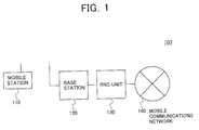
- Fig. 1 shows an example of a mobile communications system concerning the embodiments of the present invention.
- the mobile communications system 100 shown in Fig. 1 includes a mobile station 110, such as a cellular telephone terminal, a base station 120, a radio network control unit (RNC) 130 that controls the whole mobile communications system, and a mobile communications network 140.
- a mobile station 110 such as a cellular telephone terminal
- a base station 120 such as a cellular telephone terminal
- RNC radio network control unit
- a TDD method is adopted for communications between the base station 120 and the mobile station 110, and time slots are asymmetrically assigned to each of an uplink circuit that serves traffic from the mobile station 110 to the base station 120, and a downlink circuit that serves traffic from the base station 120 to the mobile station 110.
- the number of the time slots contiguously assigned to the uplink circuit may be different from the number of the time slots contiguously assigned to the downlink circuit.
- three downlink time slots can be contiguously assigned and transmitted with one uplink time slot preceding and another uplink time slot following.
- transmission power of each of the time slots that are to be contiguously assigned to the downlink circuit is decided based on factors such as the latest receiving quality measured by the mobile station 110 of the downlink time slots that are contiguously assigned to the downlink circuit, the latest receiving power measured by the base station 120 of one or more uplink time slots assigned to the uplink circuit, control delay time, and fading frequency of the communications between the mobile station 110 and the base station 120, as described in detail later.
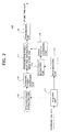
- Fig. 2 is a block diagram of an example of the mobile station 110.
- the mobile station 110 includes a receiving unit 111, a data decoding unit 112, a data quality extracting unit 113, a data quality averaging unit 114, a receiving power extracting unit 115, a receiving power averaging unit 116, a transmission power control information generating unit 117, and a transmitting unit 118.
- the receiving unit 111 receives a plurality of time slots that the base station 120 contiguously transmits on the downlink circuit.
- the downlink time slots received by the receiving unit 111 are provided to the data decoding unit 112 and the receiving power extracting unit 115.
- the data decoding unit 112 decodes each of the plurality of the time slots provided from the receiving unit 111, the time slots being contiguously assigned to the downlink circuit.
- the data decoding unit 112 decodes data by reverse diffusion using a predetermined diffusion code.
- the data quality extracting unit 113 extracts data quality values (a bit error rate, a block error rate, and the like) of each of the plurality of the time slots contiguously assigned to the downlink circuit, based on the data (decoded data) decoded by the data decoding unit 112.
- the data quality averaging unit 114 averages the data quality values of the plurality of the time slots, which are extracted by the data quality extracting unit 113.
- the averaged data quality value is provided to the transmission power control information generating unit 117.
- the last time slot of the downlink time slots contiguously assigned better represents the latest communication path conditions, rather than the earlier time slots.
- lighter weight is attached to the quality value of earlier time slots
- heavier weight is attached to the quality value of later time slots.
- the data quality averaging unit 114 assigns heavier weight to time slots that are received later, such that time slots that are closer to the subsequent time slots contribute more heavily to the calculation of the average value.
- the receiving power extracting unit 115 extracts receiving power of each of the time slots that are contiguously assigned to the downlink circuit, the time slots being provided from the receiving unit 111. Then, the receiving power extracting unit 115 calculates a signal-to-noise ratio (S/N ratio) of each time slot, based on the extracted receiving power.
- S/N ratio signal-to-noise ratio
- the receiving power averaging unit 116 averages the receiving power and the S/N ratio of all the time slots that are provided by the receiving power extracting unit 115.
- the receiving power averaging unit 116 may assign heavier weight to the receiving power and an S/N ratio of the later time slots, in averaging operations.
- the averaged receiving power and the averaged S/N ratio are provided to the transmission power control information generating unit 117.
- the transmission power control information generating unit 117 generates transmission power control information as a request for the transmission power of the time slots that are to be contiguously transmitted subsequently, based on the averaged data quality provided from the data quality averaging unit 114, and the averaged receiving power and the averaged S/N ratio that are provided from the receiving power averaging unit 116.
- the transmission power control information generating unit 117 requests that the transmission power be raised when the averaged data quality and the averaged S/N ratio are not fulfilling predetermined quality, or when the averaged receiving power is not fulfilling the predetermined power level.
- the transmission power control information generating unit 117 requests that the transmission power be lowered when the averaged data quality and the averaged S/N ratio are excessively better than the predetermined quality, or when the averaged receiving power is excessively higher than the predetermined power level.
- the data quality, the S/N ratio, and the receiving power, all combined, are called "receiving quality".
- the transmission power control information generated by the transmission power control information generating unit 117 is provided to the transmitting unit 118.
- the transmitting unit 118 modulates the transmission power control information generated by the transmission power control information generating unit 117, which is contained in an uplink time slot, and transmitted to the base station 120.
- Fig. 3 is a block diagram of an example of the base station 120.
- the base station 120 shown in Fig. 3 includes antennas for both receiving and transmitting 121-1 and 121-2, transceiver units 122-1 and 122-2, a data decoding unit 123, receiving power extracting units 124-1 and 124-2, a receiving power averaging unit 125, and a transmission power setting unit 126.
- the base station 120 is an example of a diversity configuration with the two antennas 121-1 and 121-2, wherein the transceiver units 122-1 and 122-2, and the receiving power extracting units 124-1 and 124-2 are provided corresponding to the antennas 121-1 and 121-2, respectively.
- the antenna 121-1 and the transceiver unit 122-1 receive one or more uplink time slots that are contiguously assigned and transmitted from the mobile station 110.
- the uplink time slots received by the antenna 121-1 and the transceiver unit 122-1 are provided to the data decoding unit 123 and the receiving power extracting unit 124-1.
- the antenna 121-2 and the transceiver unit 122-2 receive one or more uplink time slots that are contiguously assigned and transmitted from the mobile station 110.
- the uplink time slots received by the antenna 121-2 and the transceiver unit 122-2 are provided to the data decoding unit 123 and the receiving power extracting unit 124-2.
- the data decoding unit 123 decodes each of the one or more uplink time slots, which are contiguously assigned, provided from the transceiver units 122-1 and 122-2. Transmission power control information is included in the data that is decoded by the data decoding unit 123.
- the data decoding unit 123 extracts the transmission power control information from the decoded data, and provides the transmission power control information to the transmission power setting unit 126.
- the receiving power extracting unit 124-1 extracts a receiving power value of each of the uplink time slots provided from the transceiver unit 122-1.
- the receiving power averaging unit 125 averages the receiving power values of the time slots, the values being extracted by the receiving power extracting unit 124-1.
- the average of the receiving power values is provided to the transmission power setting unit 126.
- the receiving power extracting unit 124-2 extracts a receiving power value of each of the uplink time slots provided from the transceiver unit 122-2.
- the receiving power averaging unit 125 averages the receiving power values of the time slots, the values being extracted by the receiving power extracting unit 124-2.
- the average of the receiving power values is provided to the transmission power setting unit 126.
- the transmission power setting unit 126 sets up transmission power of subsequent downlink time slots that are contiguously assigned and to be transmitted through each of the antenna 121-1 and the antenna 121-2.
- the transmission power setting unit 126 increases the transmission power of the subsequent time slots that are contiguously assigned. Conversely, when the transmission power control information provided from the data decoding unit 123 requests that the transmission power be lowered, the transmission power setting unit 126 decreases the transmission power of the subsequent time slots that are contiguously assigned.
- the transmission power setting unit 126 distributes the power value that is either increased or decreased in the manner described above between power of the subsequent downlink time slots to be transmitted from the antenna 121-1 and power of the subsequent downlink time slots to be transmitted from the antenna 121-2, based on the ratio of the averaged receiving power value corresponding to the antenna 121-1 to the averaged receiving power value corresponding to the antenna 121-2, the power values being provided from the receiving power averaging unit 125.
- the transmission power setting unit 126 allocates the transmission power such that the ratio of the transmission power of the subsequent time slots transmitted from the antenna 121-1 to the transmission power of the subsequent time slots transmitted from the antenna 121-2 is set to 2:1.
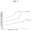
- Fig. 4 shows relations between the transmission power required sufficient to predetermined receiving quality and control delay time, with fading frequency being a parameter.
- the control delay time refers to a time lapse from a point in time when the mobile station 110 determines the averaged receiving quality to a point in time when the base station transmits the downlink time slots contiguously assigned, and a time lapse from a point in time when the base station determines the averaged receiving power to a point in time when the base station 120 transmits the downlink time slots contiguously assigned.
- the transmission power setting unit 126 acquires the fading frequency in the communication path between the mobile station 110 and the base station 120 by a predetermined method. Then, the transmission power setting unit 126 sets transmission power of each time slot of the time slots contiguously assigned to be transmitted from the antenna 121-1 such that higher transmission power is set to later time slots, and higher transmission power is set where the fading frequency is higher, based on the characteristic shown in Fig. 4. The transmission power that is set up in this manner is provided to the transceiver unit 122-1.
- the transmission power setting unit 126 sets transmission power of each time slot of the time slots contiguously assigned to be transmitted from the antenna 121-2 such that higher transmission power is set to later time slots, and higher transmission power is set where the fading frequency is high, based on the characteristic shown in Fig. 4.
- the transmission power that is set up in this manner is provided to the transceiver unit 122-2.
- the transmission power setting unit 126 may be provided with a predetermined initial power value, where the initial power value is adjusted to coincide with the transmission power of each downlink time slot to be transmitted from each of the antennas 121-1 and 121-2 in accordance with the description above.
- the antenna 121-1 and the transceiver unit 122-1 transmit at the transmission power set up by the transmission power setting unit 126 for each downlink time slot of the subsequent time slots contiguously assigned.
- the antenna 121-2 and the transceiver unit 122-2 transmit at the transmission power set up by the transmission power setting unit 126 for each downlink time slot of the subsequent time slots contiguously assigned.
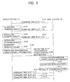
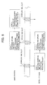
- Fig. 5 an examples is shown, where one uplink time slot and three downlink time slots that are contiguously provided are assigned.
- the base station 120 transmits the three downlink time slots 1-1, 1-2, and 1-3 one by one sequentially through the antennas 121-1 and 121-2 (Steps 101, 103, and 105).
- the mobile station 110 Each time the mobile station 110 receives the three downlink time slots 1-1, 1-2, and 1-3, the mobile station 110 extracts the receiving quality of each of the three time slots (Steps 102, 104, and 106). Then, the mobile station 110 assigns predetermined weight to the receiving quality corresponding to each of the time slots 1-1, 1-2, and 1-3, and extracts the averaged receiving quality (Step 107).
- the mobile station 110 generates the transmission power control information as a request for the transmission power of time slots 2-1, 2-2, and 2-3 that are contiguously assigned and to be transmitted next, based on the averaged receiving quality (Step 108).
- the mobile station 110 modulates the generated transmission power control information by a predetermined method, includes the modulated transmission power control information in an uplink time slot, and transmits the modulated transmission power control information to the base station 120 (Step 109).
- the base station 120 extracts the receiving power of the uplink time slot while extracting the transmission power control information from the data acquired by decoding the uplink time slot (Step 110), when the uplink time slot transmitted from the mobile station 110 is received through the antennas 121-1 and 121-2 (Step 111).
- the base station 120 sets up the transmission power (Step 112) of each of the downlink time slots 2-1, 2-2, and 2-3 that are to be transmitted next, based on the transmission power control information, the extracted receiving power, and the characteristics shown in Fig. 4, and the time slots are transmitted through each of the antennas 121-1 and 121-2 (Steps 113, 114, and 115).
- the mobile station 110 when the mobile station 110 receives the downlink time slots 2-1, 2-2, and 2-3, the mobile station 110 extracts the receiving quality as in steps 102, 104, and 106. Afterwards, operations after step 107 are repeated.
- the mobile communications system 100 sets up the transmission power of the next downlink time slots contiguously assigned based on receiving quality at the mobile station 110 of the current downlink time slots contiguously assigned, receiving power at the base station 120 of the uplink time slot, and the characteristics shown in Fig. 4.
- the number of the uplink time slots may be one, as the above example took, or larger. In this manner, appropriate transmission power is set up to each of the downlink time slots that are contiguously assigned.
- the data quality extracting unit 113 and the receiving power extracting unit 115 correspond to a downlink receiving quality value extracting means
- the data quality averaging unit 114 and the receiving power averaging unit 116 correspond to a receiving quality value averaging means.
- the transmission power setting unit 126 corresponds to a transmission power setting means
- the receiving power extracting units 124-1 and 124-2 correspond to an uplink receiving power value extracting means
- the receiving power averaging unit 125 corresponds to an uplink receiving power averaging means.
- suitable transmission power is allocated to each of the downlink time slots that are contiguously assigned for the downlink circuit, based on factors such as average receiving quality of the downlink time slots.
Landscapes
- Engineering & Computer Science (AREA)
- Computer Networks & Wireless Communication (AREA)
- Signal Processing (AREA)
- Physics & Mathematics (AREA)
- Probability & Statistics with Applications (AREA)
- Mobile Radio Communication Systems (AREA)
- Time-Division Multiplex Systems (AREA)
- Bidirectional Digital Transmission (AREA)
Abstract
Description
Claims (27)
- A transmission power setting method of a mobile communications system that employs a TDD method for communications between a base station and a mobile station, wherein a first number of downlink time slots are contiguously assigned to a downlink circuit that carries traffic from the base station to the mobile station, and a second number of uplink time slots are contiguously assigned to an uplink circuit that carries traffic from the mobile station to the base station, where the first number and the second number do not have to be equal, and transmission power of each of said downlink time slots is individually set up, comprising:the mobile station extracting receiving quality values of all the downlink time slots that are contiguously assigned as a first group,the mobile station averaging the receiving quality values of all the downlink time slots that are contiguously assigned as the first group, andthe base station setting up transmission power of each of next downlink time slots that are contiguously assigned as a second group, based on the averaged receiving quality value of the downlink time slots that are contiguously assigned as the first group.
- A transmission power setting method of a mobile communications system that employs a TDD method for communications between a base station that is equipped with a plurality of antennas, each of which is capable of both receiving and transmitting, and a mobile station, wherein a first number of downlink time slots are contiguously assigned to a downlink circuit that carries traffic from the base station to the mobile station, and a second number of uplink time slots are contiguously assigned to an uplink circuit that carries traffic from the mobile station to the base station, where the first number and the second number do not have to be equal, and transmission power of each of said downlink time slots is individually set up, comprising:the base station extracting a receiving power value of each of the uplink contiguous time slots for each of the antennas,the base station averaging the receiving power values of the contiguous uplink time slots for each of the antennas, andthe base station setting up for each of the antennas transmission power of each of the downlink time slots that are contiguously assigned and to be transmitted from the base station through each of the antennas based on the averaged receiving power of the uplink time slots.
- A transmission power setting method of a mobile communications system that employs a TDD method for communications between a base station that is equipped with a plurality of antennas, each of which is capable of both receiving and transmitting, and a mobile station, wherein a first number of downlink time slots are contiguously assigned to a downlink circuit that carries traffic from the base station to the mobile station, and a second number of uplink time slots are contiguously assigned to an uplink circuit that carries traffic from the mobile station to the base station, where the first number and the second number do not have to be equal, and transmission power of each of said downlink time slots is individually set up, comprising:the mobile station extracting receiving quality values of all the downlink time slots that are contiguously assigned as a first group,the mobile station averaging the receiving quality values of all the downlink time slots contiguously assigned as the first group,the base station extracting a receiving power value of each of the contiguous uplink time slots for each of the antennas,the base station averaging the receiving power values of the contiguous uplink time slots for each of the antennas, andthe base station setting up for each of the antennas transmission power of each of downlink time slots contiguously assigned as a second group, which are to be transmitted from the base station through each of the antennas based on the averaged receiving quality of the first group of the downlink time slots contiguously assigned, and the averaged receiving power of the contiguous uplink time slots.
- The transmission power setting method as claimed in claim 1, wherein each of the receiving quality values of all the downlink time slots is multiplied with a predetermined weighting factor, and the averaged receiving quality is obtained by averaging the receiving quality values that are weighted.
- The transmission power setting method as claimed in claim 1, wherein the transmission power of each of the downlink time slots of the second group is set up corresponding to a time lapse from a point in time when the average of the receiving quality values of the first group of the downlink time slots is obtained to a point in time when each of the time slots of the second group is transmitted.
- The transmission power setting method as claimed in claim 5, wherein an initial transmission power value is predetermined, and the transmission power of each of the downlink time slots of the second group is adjusted from the predetermined initial transmission power value according to a time lapse from a point in time when the average of the receiving quality values of the first group of the downlink time slots is obtained to a point in time when each of the time slots of the second group is transmitted.
- The transmission power setting method as claimed in claim 2, wherein the averaged receiving power value is obtained by averaging the extracted receiving power values of the uplink time slots that are weighted by a predetermined set of weighting factors.
- The transmission power setting method as claimed in claim 2, wherein the transmission power for each of the downlink time slots of the second group is set up according to a time lapse from a point in time when the averaged receiving power value is obtained for the uplink time slots to a point in time when each of the downlink time slots of the second group is transmitted.
- The transmission power setting method as claimed in claim 8, wherein an initial power value is predetermined, the transmission power value is obtained corresponding to the time lapse from the point in time when the averaged receiving power value is obtained for the uplink time slots to the time point when each of the downlink time slots of the second group is transmitted, and the initial power value is adjusted to coincide with the transmission power value.
- The transmission power setting method as claimed in claim 1, wherein the transmission power of each of the downlink time slots of the second group is set up in accordance with fading frequency in communications between the base station and the mobile station.
- The transmission power setting method as claimed in claim 10, wherein an initial transmission power is predetermined, and the transmission power of each of the downlink time slots of the second group is obtained by adjusting the initial transmission power in accordance with fading frequency in communications between the base station and the mobile station.
- A mobile communications system that employs a TDD method for communications between a base station and a mobile station, wherein a first number of downlink time slots are contiguously assigned to a downlink circuit that carries traffic from the base station to the mobile station, and a second number of uplink time slots are contiguously assigned to an uplink circuit that carries traffic from the mobile station to the base station, where the first number and the second number do not have to be equal, and transmission power of each of said downlink time slots is individually set up, comprising:downlink receiving quality value extracting means provided in the mobile station, for extracting receiving quality values of each of the plurality of downlink time slots that are transmitted as a first group,downlink receiving quality value averaging means provided in the mobile station, for averaging quality values of the downlink time slots that are contiguously transmitted as the first group, andtransmission power setting means provided in the base station, for setting up transmission power for each of downlink time slots that are to be transmitted as a second group, which are contiguously assigned to the downlink circuit.
- The mobile communications system as claimed in claim 12, wherein the downlink receiving quality averaging means attaches weight, according to a predetermined set of weighting factors, to each of the downlink receiving quality values of the downlink time slots of the first group, and the downlink receiving quality averaging means averages the downlink receiving quality values that are weighted hereinabove.
- A mobile communications system as claimed in claim 12, wherein the transmission power setting means sets up the transmission power for each of the downlink time slots that are to be contiguously transmitted as the second group according to a time lapse from a point in time when the average of the receiving quality values of the first group of the downlink time slots is obtained to a point in time when each of the time slots of the second group is transmitted.
- The mobile communication system as claimed in claim 14, where in the transmission power setting means comprises a predetermined initial transmission power value, and the transmission power of each of the downlink time slots of the second group is adjusted from the predetermined initial transmission power value according to a time lapse from a point in time when the average of the receiving quality values of the first group of the downlink time slots is obtained to a point in time when each of the time slots of the second group is transmitted.
- A mobile communications system as claimed in claim 12, wherein the base station comprises:a plurality of antennas, each of which is capable of both receiving and transmitting,an uplink receiving power value extracting unit that extracts receiving power values of all contiguous uplink time slots for each of the antennas, andan uplink receiving power averaging unit that averages the receiving power values of the contiguous uplink time slots for each of the antennas, andthe base station sets up for each of the antennas the transmission power of each of the downlink time slots contiguously assigned of the second group that is to be transmitted next from the base station through each of the antennas based on the averaged receiving power value of the contiguous uplink time slots.
- The mobile communications system as claimed in claim 16, wherein the uplink receiving power averaging means attaches weight, according to a predetermined set of weighting factors, to each of the receiving power values of the uplink time slots, and averages the receiving power values that are weighted hereinabove.
- The mobile communications system as claimed in claim 16, wherein the transmission power setting means sets up the transmission power for each of the downlink time slots of the second group according to a time lapse from a point in time when the averaged receiving power value is obtained for the uplink time slots to a point in time when each of the downlink time slots of the second group is transmitted.
- The mobile communications system as claimed in claim 18, wherein the transmission power setting means provides a initial power value that is predetermined, and the transmission power value is obtained according to the time lapse from the point in time when the averaged receiving power value is obtained for the uplink time slots to the time point when each of the downlink time slots of the second group is transmitted, and the initial power value is adjusted to match the transmission power value.
- The mobile communications system as claimed in claim 12, wherein the transmission power setting means sets up the transmission power of each of the downlink time slots of the second group according to fading frequency of communications between the base station and the mobile station.
- The mobile communications system as claimed in claim 20, wherein the transmission power setting means provides an initial transmission power value that is predetermined, and the transmission power of each of the downlink time slots of the second group is obtained by adjusting the initial transmission power value in accordance with the fading frequency of the communications between the base station and the mobile station.
- A base station of a mobile communications system that employs a TDD method for communications with a mobile station, wherein a first number of downlink time slots are contiguously assigned to a downlink circuit that carries traffic from the base station to the mobile station, and a second number of uplink time slots are contiguously assigned to an uplink circuit that carries traffic from the mobile station to the base station, where the first number and the second number do not have to be equal, comprising:a plurality of antennas, each of which is capable of both receiving and transmitting,an uplink receiving power value extracting unit that extracts receiving power values of all contiguous uplink time slots for each of the antennas,an uplink receiving power averaging unit that averages the receiving power values of the contiguous uplink time slots for each of the antennas, anda transmission power setting unit that sets up transmission power, for each of the antennas, of each of downlink time slots contiguously assigned that are to be transmitted next from the base station through each of the antennas based on the averaged receiving power value of the contiguous uplink time slots.
- The base station as claimed in claim 22, wherein the uplink receiving power averaging unit attaches weight according to a predetermined set of weighting factors to each of the receiving power values of the uplink time slots, and averages the receiving power values that are weighted hereinabove.
- The base station as claimed in claim 22, wherein the transmission power setting unit sets up the transmission power for each of the downlink time slots that are to be sent next according to a time lapse from a point in time when the averaged receiving power value is obtained for the uplink time slots to a point in time when each of the downlink time slots that are to be transmitted next.
- The base station as claimed in claim 24, wherein the transmission power setting unit provides an initial power value that is predetermined, and the transmission power value is obtained according to the time lapse from the point in time when the averaged receiving power value is obtained for the uplink time slots to the time point when each of the downlink time slots that are to be transmitted next is transmitted, and the initial power value is adjusted to coincide with the transmission power value.
- The base station as claimed in claim 22, wherein the transmission power setting unit sets up the transmission power of each of the downlink time slots that are to be transmitted next according to fading frequency of communications between the base station and the mobile station.
- The base station as claimed in claim 26, wherein the transmission power setting unit provides an initial transmission power valuethat is predetermined, and the transmission power of each of the downlink time slots that are to be transmitted next is obtained by adjusting the initial transmission power value in accordance with the fading frequency of the communications between the base station and the mobile station.
Applications Claiming Priority (2)
| Application Number | Priority Date | Filing Date | Title |
|---|---|---|---|
| JP2001319347 | 2001-10-17 | ||
| JP2001319347A JP3865212B2 (en) | 2001-10-17 | 2001-10-17 | Transmission power setting method, mobile communication system, and base station |
Publications (3)
| Publication Number | Publication Date |
|---|---|
| EP1304817A2 true EP1304817A2 (en) | 2003-04-23 |
| EP1304817A3 EP1304817A3 (en) | 2003-10-01 |
| EP1304817B1 EP1304817B1 (en) | 2006-02-15 |
Family
ID=19136913
Family Applications (1)
| Application Number | Title | Priority Date | Filing Date |
|---|---|---|---|
| EP02257181A Expired - Lifetime EP1304817B1 (en) | 2001-10-17 | 2002-10-16 | A transmission power setting method, a mobile communications system, and a base station |
Country Status (5)
| Country | Link |
|---|---|
| US (1) | US20030072274A1 (en) |
| EP (1) | EP1304817B1 (en) |
| JP (1) | JP3865212B2 (en) |
| CN (1) | CN100471333C (en) |
| DE (1) | DE60209191T2 (en) |
Families Citing this family (14)
| Publication number | Priority date | Publication date | Assignee | Title |
|---|---|---|---|---|
| WO2005069504A1 (en) * | 2003-12-22 | 2005-07-28 | Nokia Corporation | Method, device and system with signal quality target for radio frequency power control in cellular systems |
| JP2007067584A (en) * | 2005-08-29 | 2007-03-15 | Kyocera Corp | Time slot control method, communication system, communication apparatus, and program |
| JP2007274336A (en) * | 2006-03-31 | 2007-10-18 | Fujitsu Ltd | Radio base station and radio terminal |
| US7885235B2 (en) | 2006-09-26 | 2011-02-08 | Mitsubishi Electric Corporation | Data communication method and mobile communication system |
| CN101262275B (en) * | 2007-03-06 | 2012-11-28 | 中兴通讯股份有限公司 | Power allocation and adjusting method based on feedback link quality of external code enhancement technology |
| JP4383480B2 (en) * | 2007-11-15 | 2009-12-16 | 株式会社エヌ・ティ・ティ・ドコモ | Mobile communication terminal and transmission power control method in mobile communication terminal |
| CN101562474B (en) * | 2008-04-15 | 2013-05-08 | 杰脉通信技术(上海)有限公司 | Method for detecting uplink synchronizing signals |
| CN102006656A (en) * | 2009-09-01 | 2011-04-06 | 中兴通讯股份有限公司 | Transmitting power processing method and device |
| JP4975160B2 (en) * | 2010-12-17 | 2012-07-11 | 三菱電機株式会社 | Data communication method, mobile communication system |
| CN107104765B (en) | 2011-02-11 | 2020-10-16 | 寰发股份有限公司 | User equipment reference signal receiving quality measuring method and user equipment |
| US9596658B2 (en) * | 2012-05-31 | 2017-03-14 | Mediatek Inc. | Power control methods |
| US9078179B2 (en) * | 2012-11-16 | 2015-07-07 | Qualcomm Incorporated | IRAT measurement reporting method in TD-SCDMA |
| WO2016150513A1 (en) * | 2015-03-26 | 2016-09-29 | Sony Corporation | Scheduling in cellular networks |
| CN107432025B (en) | 2015-03-25 | 2021-09-17 | 索尼集团公司 | Node and execution method thereof, relay node and execution method thereof |
Family Cites Families (12)
| Publication number | Priority date | Publication date | Assignee | Title |
|---|---|---|---|---|
| SE467332B (en) * | 1990-06-21 | 1992-06-29 | Ericsson Telefon Ab L M | PROCEDURE FOR POWER CONTROL IN A DIGITAL MOBILE PHONE SYSTEM |
| US6122260A (en) * | 1996-12-16 | 2000-09-19 | Civil Telecommunications, Inc. | Smart antenna CDMA wireless communication system |
| KR20000022672A (en) * | 1998-09-07 | 2000-04-25 | 마츠시타 덴끼 산교 가부시키가이샤 | Mobile station communication apparatus, base station communication apparatus, and wireless communication method |
| GB9823396D0 (en) * | 1998-10-27 | 1998-12-23 | Roke Manor Research | Method of and apparatus for power control |
| DE19917061A1 (en) * | 1999-04-15 | 2000-11-02 | Siemens Ag | Procedure for setting the transmission power in radio communication systems |
| US7139592B2 (en) * | 1999-06-21 | 2006-11-21 | Arraycomm Llc | Null deepening for an adaptive antenna based communication station |
| US6728228B1 (en) * | 1999-09-20 | 2004-04-27 | Telefonaktiebolaget Lm Ericsson (Publ) | Method and system for measuring and reporting received signal strength |
| JP3621310B2 (en) * | 1999-10-07 | 2005-02-16 | 松下電器産業株式会社 | Wireless communication apparatus and transmission power control method |
| DE19957299B4 (en) * | 1999-11-29 | 2009-02-26 | Siemens Ag | Method for transmission power control in a radio communication system |
| KR100860804B1 (en) * | 2000-05-01 | 2008-09-30 | 인터디지탈 테크날러지 코포레이션 | Spread spectrum time division user equipment for multiple downlink time slots |
| US6853633B1 (en) * | 2000-09-26 | 2005-02-08 | Ericsson Inc. | Methods of providing signal parameter information using delta-modulation and related systems and terminals |
| JP3543759B2 (en) * | 2000-11-15 | 2004-07-21 | 日本電気株式会社 | Transmission power control method, transmitting / receiving apparatus, base station and mobile station |
-
2001
- 2001-10-17 JP JP2001319347A patent/JP3865212B2/en not_active Expired - Fee Related
-
2002
- 2002-10-16 EP EP02257181A patent/EP1304817B1/en not_active Expired - Lifetime
- 2002-10-16 DE DE60209191T patent/DE60209191T2/en not_active Expired - Lifetime
- 2002-10-16 US US10/270,644 patent/US20030072274A1/en not_active Abandoned
- 2002-10-17 CN CNB021475792A patent/CN100471333C/en not_active Expired - Fee Related
Also Published As
| Publication number | Publication date |
|---|---|
| CN1413042A (en) | 2003-04-23 |
| DE60209191T2 (en) | 2006-08-03 |
| JP3865212B2 (en) | 2007-01-10 |
| EP1304817B1 (en) | 2006-02-15 |
| DE60209191D1 (en) | 2006-04-20 |
| JP2003124877A (en) | 2003-04-25 |
| CN100471333C (en) | 2009-03-18 |
| US20030072274A1 (en) | 2003-04-17 |
| EP1304817A3 (en) | 2003-10-01 |
Similar Documents
| Publication | Publication Date | Title |
|---|---|---|
| JP4455768B2 (en) | Method and apparatus for power allocation on a reverse link power control channel in a communication system | |
| US7529548B2 (en) | Method and system for adapting a wireless link to achieve a desired channel quality | |
| EP1231807B1 (en) | Controlling data transmission rate on the reserve link for each mobile station in a dedicated manner | |
| US8537875B2 (en) | Methods and apparatus for adjusting forward link signal to interference and noise ratio estimates | |
| JP4385489B2 (en) | COMMUNICATION SYSTEM, COMMUNICATION METHOD, AND COMMUNICATION DEVICE | |
| EP0961417A2 (en) | Method for power control during call acquisition in cdma mobile communication systems | |
| EP0767548A2 (en) | Code division multiple access system providing load and interference based demand assignment service to users | |
| EP1304817B1 (en) | A transmission power setting method, a mobile communications system, and a base station | |
| US20020155840A1 (en) | Base station device and wireless communication method | |
| EP1871131A1 (en) | Mobile communication system, mobile station, base station, and communication control method | |
| JP2007500477A (en) | Method and apparatus for assigning output to control channel in communication system | |
| KR20010073145A (en) | Method and apparatus for distributed optimal reverse link scheduling of resources, such as rate and power, in a wireless communication system | |
| US7170943B1 (en) | Control channel for a wireless digital subscriber line system | |
| CN101536564B (en) | Method for transmitting data packets using different frequency reuse factors | |
| EP1309106A1 (en) | Control of the data rate of the downlink shared channel based on power control information | |
| US20040120289A1 (en) | Transmission of information in a wireless communication system | |
| EP1295408B1 (en) | Adaptive rate power control cdma system | |
| AU2001270412A1 (en) | Control channel for a wireless digital subscriber line system | |
| US20050185594A1 (en) | Method of selecting transport channel parameters, radio system, controller, user equipment and base station | |
| US20040022189A1 (en) | Equalizing signal-to-interference ratios of different physical channels supporting a coded composite transport channel | |
| EP0999657A2 (en) | CDMA transmission power control capable of preventing call disconnection and degradation of capacity of subscribers | |
| US20030076874A1 (en) | Reverse synchronization method in a wireless system | |
| CN1385012A (en) | Method for synchronising uplink signal transmission in radio communication system | |
| EP1102422A1 (en) | Method and system for improving transmission efficiency in TDMA multi-carrier communication systems | |
| AU2001270411B2 (en) | Adaptive rate power control CDMA system |
Legal Events
| Date | Code | Title | Description |
|---|---|---|---|
| PUAI | Public reference made under article 153(3) epc to a published international application that has entered the european phase |
Free format text: ORIGINAL CODE: 0009012 |
|
| 17P | Request for examination filed |
Effective date: 20021026 |
|
| AK | Designated contracting states |
Designated state(s): AT BE BG CH CY CZ DE DK EE ES FI FR GB GR IE IT LI LU MC NL PT SE SK TR |
|
| AX | Request for extension of the european patent |
Extension state: AL LT LV MK RO SI |
|
| PUAL | Search report despatched |
Free format text: ORIGINAL CODE: 0009013 |
|
| AK | Designated contracting states |
Kind code of ref document: A3 Designated state(s): AT BE BG CH CY CZ DE DK EE ES FI FR GB GR IE IT LI LU MC NL PT SE SK TR |
|
| AX | Request for extension of the european patent |
Extension state: AL LT LV MK RO SI |
|
| RIC1 | Information provided on ipc code assigned before grant |
Ipc: 7H 04B 7/005 A Ipc: 7H 04B 7/06 B |
|
| PUAF | Information related to the publication of a search report (a3 document) modified or deleted |
Free format text: ORIGINAL CODE: 0009199SEPU |
|
| PUAL | Search report despatched |
Free format text: ORIGINAL CODE: 0009013 |
|
| D17D | Deferred search report published (deleted) | ||
| AK | Designated contracting states |
Kind code of ref document: A3 Designated state(s): AT BE BG CH CY CZ DE DK EE ES FI FR GB GR IE IT LI LU MC NL PT SE SK TR |
|
| AX | Request for extension of the european patent |
Extension state: AL LT LV MK RO SI |
|
| AKX | Designation fees paid |
Designated state(s): DE GB |
|
| 17Q | First examination report despatched |
Effective date: 20040812 |
|
| GRAP | Despatch of communication of intention to grant a patent |
Free format text: ORIGINAL CODE: EPIDOSNIGR1 |
|
| GRAS | Grant fee paid |
Free format text: ORIGINAL CODE: EPIDOSNIGR3 |
|
| GRAA | (expected) grant |
Free format text: ORIGINAL CODE: 0009210 |
|
| AK | Designated contracting states |
Kind code of ref document: B1 Designated state(s): DE GB |
|
| REG | Reference to a national code |
Ref country code: GB Ref legal event code: FG4D |
|
| REF | Corresponds to: |
Ref document number: 60209191 Country of ref document: DE Date of ref document: 20060420 Kind code of ref document: P |
|
| PLBE | No opposition filed within time limit |
Free format text: ORIGINAL CODE: 0009261 |
|
| STAA | Information on the status of an ep patent application or granted ep patent |
Free format text: STATUS: NO OPPOSITION FILED WITHIN TIME LIMIT |
|
| 26N | No opposition filed |
Effective date: 20061116 |
|
| PGFP | Annual fee paid to national office [announced via postgrant information from national office to epo] |
Ref country code: DE Payment date: 20101013 Year of fee payment: 9 |
|
| PGFP | Annual fee paid to national office [announced via postgrant information from national office to epo] |
Ref country code: GB Payment date: 20101013 Year of fee payment: 9 |
|
| GBPC | Gb: european patent ceased through non-payment of renewal fee |
Effective date: 20121016 |
|
| PG25 | Lapsed in a contracting state [announced via postgrant information from national office to epo] |
Ref country code: GB Free format text: LAPSE BECAUSE OF NON-PAYMENT OF DUE FEES Effective date: 20121016 Ref country code: DE Free format text: LAPSE BECAUSE OF NON-PAYMENT OF DUE FEES Effective date: 20130501 |
|
| REG | Reference to a national code |
Ref country code: DE Ref legal event code: R119 Ref document number: 60209191 Country of ref document: DE Effective date: 20130501 |