EP1304725A2 - Electrodeless discharge lamp using microwave energy - Google Patents
Electrodeless discharge lamp using microwave energy Download PDFInfo
- Publication number
- EP1304725A2 EP1304725A2 EP02013223A EP02013223A EP1304725A2 EP 1304725 A2 EP1304725 A2 EP 1304725A2 EP 02013223 A EP02013223 A EP 02013223A EP 02013223 A EP02013223 A EP 02013223A EP 1304725 A2 EP1304725 A2 EP 1304725A2
- Authority
- EP
- European Patent Office
- Prior art keywords
- resonator
- lamp
- bulb
- microwave energy
- casing
- Prior art date
- Legal status (The legal status is an assumption and is not a legal conclusion. Google has not performed a legal analysis and makes no representation as to the accuracy of the status listed.)
- Withdrawn
Links
Images



Classifications
-
- H—ELECTRICITY
- H01—ELECTRIC ELEMENTS
- H01J—ELECTRIC DISCHARGE TUBES OR DISCHARGE LAMPS
- H01J65/00—Lamps without any electrode inside the vessel; Lamps with at least one main electrode outside the vessel
- H01J65/04—Lamps in which a gas filling is excited to luminesce by an external electromagnetic field or by external corpuscular radiation, e.g. for indicating plasma display panels
-
- H—ELECTRICITY
- H01—ELECTRIC ELEMENTS
- H01J—ELECTRIC DISCHARGE TUBES OR DISCHARGE LAMPS
- H01J65/00—Lamps without any electrode inside the vessel; Lamps with at least one main electrode outside the vessel
- H01J65/04—Lamps in which a gas filling is excited to luminesce by an external electromagnetic field or by external corpuscular radiation, e.g. for indicating plasma display panels
- H01J65/042—Lamps in which a gas filling is excited to luminesce by an external electromagnetic field or by external corpuscular radiation, e.g. for indicating plasma display panels by an external electromagnetic field
- H01J65/044—Lamps in which a gas filling is excited to luminesce by an external electromagnetic field or by external corpuscular radiation, e.g. for indicating plasma display panels by an external electromagnetic field the field being produced by a separate microwave unit
Definitions
- the present invention relates to a lighting apparatus using microwave energy, and in particular to an electrodeless discharge lamp using microwave energy which is capable of being applied to various fields by having a compact construction.
- An electrodeless discharge lamp emits lights by enclosing a certain amount of inert gas such as argon and materials such as halide, etc. generating plasmas and exciting them with microwave energy.
- the electrodeless discharge lamp has longer lifespan and shows better lighting efficiency than that of an incandescent lamp and a fluorescent lamp.
- the wave guide 105 is formed so as to have a regular square-shaped section in the travel direction of microwave energy in order to transmit microwave energy having a certain frequency, and a high voltage generator 113 is placed so as to be opposite to the magnetron 103 on the basis of the wave guide 105 (placed between them) and provides high voltage power.
- a cooling fan 115 being rotated by the fan motor 116 is installed to the lower portion of the bulb motor 109 in order to cool the magnetron 103 and the high voltage generator 113.
- microwave energy transmitted to a free space turns into a transmission mode traveling in a direction at a right angle to an electric field and a magnetic field, namely, a TEM (Transverse Electromagnetic) mode.
- TEM Transverse Electromagnetic
- a wave guide placed between a magnetron and a mesh screen and having a certain size in consideration of a standard of a transmission frequency a TE mode or a TM mode is used or a cylindrical wave guide having a certain diameter is used.
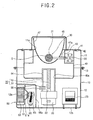
- the resonator 40 has a cylindrical shape in general, however there also can be a rectangular resonator or a polygonal resonator, the resonator 40 is made of metal materials so as to prevent leakage of microwave energy and lights, has a flange portion 41 on the outer circumferential surface and is fixed inside the front casing 11 by a screw 42.
- a slot 54 for outputting microwave energy is formed at a portion inserted into the resonator 40, and a matching tune stub 56 for matching of impedance is placed at the side at which the magnetron 20 is installed.
- the inner guide 51 has a length shorter than that of the external guide 53 and is placed so as to have a certain distance from the antenna 22 of the magnetron 20.
- the slot 54 formed at the external guide 53 can be variously formed.
- the slot 54 can have a ' ⁇ ' shape in the circumferential direction of the external guide 53, as depicted in Figures 4B and 4C, it can have a 'U' shape or a '+' shape. And, as depicted in Figures 4D and 4E, it can have a structure slanting to the length direction of the external guide 53 or a spiral shape formed on the circumference of the external guide 53.
- a reflecting surface having a parabolic shape so as to reflect lights emitted from the bulb 30 toward the front is formed, and the opening portion is exposed through the opening portion 11a of the casing 10.
- the lights generated in the bulb 30 is reflected toward the front by the reflector 47, the mesh member 45 placed in front of the reflector 47 prevents leakage of microwave energy at the resonation region inside the resonator 40 and passes the light generated from the bulb 30, accordingly the lights can be transmitted toward the front.
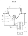
- holes 47a', 10a' are formed at the central portion of the reflector 47' and the casing 10' in order to pass the stem 32' and the motor shaft 35' connecting the bulb 30' and the bulb motor 33', and a bulb motor 33' is fixed to the rear of the casing 10'.
- a general sealing structure (not shown) is secured between the hole 10a' of the casing 10' and the motor shaft 35' or the bulb motor 33' and the rear surface of the casing 10' in order to prevent leakage of microwave energy or penetration of external air.
Landscapes
- Physics & Mathematics (AREA)
- Engineering & Computer Science (AREA)
- Plasma & Fusion (AREA)
- Electromagnetism (AREA)
- Non-Portable Lighting Devices Or Systems Thereof (AREA)
- Discharge Lamps And Accessories Thereof (AREA)
- Circuit Arrangements For Discharge Lamps (AREA)
Abstract
Description
Claims (20)
- An electrodeless discharge lamp using microwave energy, comprising:a resonator having an opening portion at the side and forming a resonance region at which microwave energy is resonated;a microwave generator having an antenna in order to output microwave energy;a coaxial wave guide installed to the other side of the resonator, transmitting microwave energy from the microwave generator to the resonator and having an internal guide extended in the projecting direction of the antenna of the microwave generator;a bulb placed inside the resonator and having enclosed fluorescent materials generating lights by the microwave energy; anda mesh member installed to the opening portion of the resonator, preventing leakage of microwave energy and passing lights generated in the bulb.
- The lamp of claim 1, wherein the microwave generator, the coaxial wave guide, the resonator, the bulb and the mesh member are combined and arranged in the same axial direction.
- The lamp of claim 1, wherein the resonator, the bulb and the mesh member are combined and arranged in the same axial direction, and the microwave generator and the coaxial wave guide are arranged in another axial direction adjacent to the axial direction of the resonator, the bulb and the mesh member.
- The lamp of claim 1, wherein the coaxial wave guide is constructed with a cylinder-shaped external guide having a path for transmitting microwave energy and an internal guide extended from the central portion of the external guide toward the projecting direction of the antenna of the microwave generator.
- The lamp of claim 4, wherein the external guide has an opened structure so as to be directly combined with the microwave generator and has a slot formed at the portion inserted into the resonator in order to output microwave energy.
- The lamp of claim 5, wherein the slot is lengthwise formed in the circumferential direction of the external guide.
- The lamp of claim 5, wherein the slot has a 'U' shape.
- The lamp of claim 5, wherein the slot has a cross shape.
- The lamp of claim 5, wherein the slot slants in the length direction of the external guide.
- The lamp of claim 5, wherein the slot has a spiral shape on the circumference of the external guide.
- The lamp of claim 1, wherein a matching tune stub is installed to the side of the coaxial wave guide.
- The lamp of claim 1, wherein a reflector is installed inside the mesh member of the opening portion of the resonator in order to reflect lights generated in the bulb toward the front.
- The lamp of claim 1, further comprising:a bulb rotation operating means for rotating the bulb.
- The lamp of claim 13, wherein the bulb rotation operating means includes a bulb motor supported by the resonator and a motor shaft connected between the bulb motor and the bulb and transmitting a rotational force.
- The lamp of claim 14, wherein the resonator has a divided space at which the bulb motor is installed.
- The lamp of claim 14, wherein the bulb rotation operating means is placed so as to pass the center of the resonator, and the coaxial wave guide is placed at a portion separated from the center of the resonator.
- The lamp of claim 1, wherein the microwave generator, the coaxial wave guide and the resonator are placed inside a casing having an opening portion at the side.
- The lamp of claim 17, wherein the microwave generator is a magnetron, and a high voltage generator is placed inside the casing in order to provide a boosted high voltage to the magnetron.
- The lamp of claim 18, wherein a cooling device for cooling the magnetron and the high voltage generator is placed inside the casing.
- The lamp of claim 19, wherein a suction hole and a discharge hole are formed at the casing in order to circulate external air, and the cooling device includes a fan housing placed inside the casing, a cooling fan installed inside the fan housing and forcibly circulating external air and a fan motor rotating the cooling fan.
Applications Claiming Priority (2)
| Application Number | Priority Date | Filing Date | Title |
|---|---|---|---|
| KR10-2001-0060190A KR100393816B1 (en) | 2001-09-27 | 2001-09-27 | Electrodeless discharge lamp using microwave |
| KR2001060190 | 2001-09-27 |
Publications (2)
| Publication Number | Publication Date |
|---|---|
| EP1304725A2 true EP1304725A2 (en) | 2003-04-23 |
| EP1304725A3 EP1304725A3 (en) | 2007-02-14 |
Family
ID=19714764
Family Applications (1)
| Application Number | Title | Priority Date | Filing Date |
|---|---|---|---|
| EP02013223A Withdrawn EP1304725A3 (en) | 2001-09-27 | 2002-06-15 | Electrodeless discharge lamp using microwave energy |
Country Status (6)
| Country | Link |
|---|---|
| US (1) | US6960885B2 (en) |
| EP (1) | EP1304725A3 (en) |
| JP (1) | JP4170681B2 (en) |
| KR (1) | KR100393816B1 (en) |
| CN (1) | CN1251299C (en) |
| RU (1) | RU2223572C1 (en) |
Cited By (1)
| Publication number | Priority date | Publication date | Assignee | Title |
|---|---|---|---|---|
| EP1519408A2 (en) * | 2003-09-03 | 2005-03-30 | Lg Electronics Inc. | Electrodeless lighting system |
Families Citing this family (18)
| Publication number | Priority date | Publication date | Assignee | Title |
|---|---|---|---|---|
| KR20030042724A (en) * | 2001-11-23 | 2003-06-02 | 주식회사 엘지이아이 | Microwave lighting system |
| KR100531804B1 (en) * | 2002-12-17 | 2005-12-02 | 엘지전자 주식회사 | Plasma lighting system |
| KR100618414B1 (en) * | 2003-01-15 | 2006-08-30 | (주)포리코리아 | Engine lifting device |
| KR100556782B1 (en) * | 2003-12-06 | 2006-03-10 | 엘지전자 주식회사 | Plasma lamp system |
| KR100575666B1 (en) | 2003-12-13 | 2006-05-03 | 엘지전자 주식회사 | Plasma lamp system |
| KR100608882B1 (en) * | 2004-06-30 | 2006-08-08 | 엘지전자 주식회사 | Waveguide System for Electrodeless Lighting Equipment |
| KR20060036839A (en) * | 2004-10-26 | 2006-05-02 | 엘지전자 주식회사 | Light Bulb Structure of Electrodeless Lighting Equipment Using Plasma and Its Manufacturing Method |
| AU2006287472A1 (en) * | 2005-09-08 | 2007-03-15 | Noarc, Llc | Motion picture projector with electrodeless light source |
| KR100748529B1 (en) * | 2005-09-23 | 2007-08-13 | 엘지전자 주식회사 | High temperature operating electrodeless bulb of electrodeless lighting device and electrodeless lighting device having same |
| CN101243541B (en) * | 2006-03-14 | 2010-10-06 | Lg电子株式会社 | Device for preventing leakage of material in bulbs of plasma lighting systems |
| CN201004452Y (en) * | 2006-07-07 | 2008-01-09 | 李振达 | A fully sealed microwave sulfur lamp |
| KR100823932B1 (en) * | 2007-03-30 | 2008-04-22 | 엘지전자 주식회사 | Electrodeless lighting equipment |
| CN102144278B (en) * | 2008-09-05 | 2014-04-09 | 马田专业公司 | Light fixture with electrodeless plasma source |
| DE102009018840A1 (en) * | 2009-04-28 | 2010-11-25 | Auer Lighting Gmbh | plasma lamp |
| GB201011303D0 (en) * | 2010-07-05 | 2010-08-18 | Ann Polytechnic | Proposal for a disclosure on the dimensions of plasma crucibles |
| DE102011054760B4 (en) * | 2011-10-24 | 2014-07-24 | Boris Lutterbach | Electrodeless plasma lighting device with a lamp body on a mounted with spring tongues rotatable shaft |
| KR102512098B1 (en) * | 2020-10-14 | 2023-03-17 | 박범규 | Electroless lighting equipment using indium bromide plasma |
| CN117681551A (en) * | 2023-12-28 | 2024-03-12 | 青岛莱伊迪光电科技有限公司 | A microwave UV curing drying system for printing |
Family Cites Families (13)
| Publication number | Priority date | Publication date | Assignee | Title |
|---|---|---|---|---|
| CA1024246A (en) * | 1973-08-22 | 1978-01-10 | Donald M. Spero | Apparatus and method for generating radiation |
| JPS55154055A (en) * | 1979-05-18 | 1980-12-01 | Oak Seisakusho:Kk | No-electrode discharge tube device |
| US4485332A (en) * | 1982-05-24 | 1984-11-27 | Fusion Systems Corporation | Method & apparatus for cooling electrodeless lamps |
| US4975625A (en) * | 1988-06-24 | 1990-12-04 | Fusion Systems Corporation | Electrodeless lamp which couples to small bulb |
| US5525865A (en) * | 1994-02-25 | 1996-06-11 | Fusion Lighting, Inc. | Compact microwave source for exciting electrodeless lamps |
| JPH08222187A (en) * | 1995-02-14 | 1996-08-30 | Sony Corp | Light source |
| US5841233A (en) * | 1996-01-26 | 1998-11-24 | Fusion Lighting, Inc. | Method and apparatus for mounting a dichroic mirror in a microwave powered lamp assembly using deformable tabs |
| US5866990A (en) * | 1996-01-26 | 1999-02-02 | Fusion Lighting, Inc. | Microwave lamp with multi-purpose rotary motor |
| US6049170A (en) * | 1996-11-01 | 2000-04-11 | Matsushita Electric Industrial Co., Ltd. | High frequency discharge energy supply means and high frequency electrodeless discharge lamp device |
| RU2152666C1 (en) * | 1998-10-09 | 2000-07-10 | Козлов Александр Николаевич | Non-electrode lamp with controlled spectrum |
| WO2000070651A1 (en) * | 1999-05-12 | 2000-11-23 | Fusion Lighting, Inc. | High brightness microwave lamp |
| RU2156517C1 (en) * | 1999-06-25 | 2000-09-20 | Корчагин Юрий Владимирович | Method for excitation and keeping discharge in non-electrode valve and device which implements said method |
| KR100314080B1 (en) * | 1999-11-26 | 2001-11-15 | 구자홍 | A mirror mounting structure for plasma lamp |
-
2001
- 2001-09-27 KR KR10-2001-0060190A patent/KR100393816B1/en not_active Expired - Fee Related
-
2002
- 2002-05-21 US US10/151,095 patent/US6960885B2/en not_active Expired - Fee Related
- 2002-05-23 RU RU2002113537/09A patent/RU2223572C1/en not_active IP Right Cessation
- 2002-05-30 CN CNB021222223A patent/CN1251299C/en not_active Expired - Fee Related
- 2002-06-15 EP EP02013223A patent/EP1304725A3/en not_active Withdrawn
- 2002-06-18 JP JP2002177345A patent/JP4170681B2/en not_active Expired - Fee Related
Cited By (1)
| Publication number | Priority date | Publication date | Assignee | Title |
|---|---|---|---|---|
| EP1519408A2 (en) * | 2003-09-03 | 2005-03-30 | Lg Electronics Inc. | Electrodeless lighting system |
Also Published As
| Publication number | Publication date |
|---|---|
| CN1251299C (en) | 2006-04-12 |
| KR100393816B1 (en) | 2003-08-02 |
| KR20030028186A (en) | 2003-04-08 |
| EP1304725A3 (en) | 2007-02-14 |
| JP2003109407A (en) | 2003-04-11 |
| JP4170681B2 (en) | 2008-10-22 |
| US6960885B2 (en) | 2005-11-01 |
| RU2223572C1 (en) | 2004-02-10 |
| US20030057842A1 (en) | 2003-03-27 |
| CN1411031A (en) | 2003-04-16 |
Similar Documents
| Publication | Publication Date | Title |
|---|---|---|
| US6960885B2 (en) | Electrodeless discharge lamp excited using microwave energy coupled through a coaxial waveguide | |
| US7276860B2 (en) | Electrodeless lighting system | |
| US7161304B2 (en) | Electrodeless lighting system | |
| US6680576B2 (en) | Lighting apparatus using microwave | |
| US6979952B2 (en) | Electrodeless lamp system with orthogonally disposed resonance units | |
| US20040113559A1 (en) | Cooling apparatus of plasma lighting system | |
| RU2002113537A (en) | Microwave-free discharge lamp using microwave energy | |
| US7081702B2 (en) | Electrodeless lighting system | |
| US7196474B2 (en) | Electrodeless lighting apparatus | |
| CN101243541B (en) | Device for preventing leakage of material in bulbs of plasma lighting systems | |
| RU2226017C2 (en) | Electrode-free lighting system ( variants ) | |
| US7126282B2 (en) | Electrodeless lighting system | |
| JP4259274B2 (en) | Microwave electrodeless discharge lamp device | |
| KR100565225B1 (en) | Plasma Lamp System and Projection Television Using the System | |
| KR100724461B1 (en) | Electrodeless illuminator with plate resonator | |
| KR100608881B1 (en) | Initial lighting device of electrodeless lighting equipment | |
| KR20020059536A (en) | The microwave lighting apparatus | |
| KR20060128502A (en) | Electrodeless lighting equipment | |
| KR20070039304A (en) | Medium power electrodeless lighting equipment with initial lighting means |
Legal Events
| Date | Code | Title | Description |
|---|---|---|---|
| PUAI | Public reference made under article 153(3) epc to a published international application that has entered the european phase |
Free format text: ORIGINAL CODE: 0009012 |
|
| 17P | Request for examination filed |
Effective date: 20020615 |
|
| AK | Designated contracting states |
Designated state(s): AT BE CH CY DE DK ES FI FR GB GR IE IT LI LU MC NL PT SE TR |
|
| AX | Request for extension of the european patent |
Extension state: AL LT LV MK RO SI |
|
| PUAL | Search report despatched |
Free format text: ORIGINAL CODE: 0009013 |
|
| AK | Designated contracting states |
Kind code of ref document: A3 Designated state(s): AT BE CH CY DE DK ES FI FR GB GR IE IT LI LU MC NL PT SE TR |
|
| AX | Request for extension of the european patent |
Extension state: AL LT LV MK RO SI |
|
| 17Q | First examination report despatched |
Effective date: 20070716 |
|
| AKX | Designation fees paid |
Designated state(s): DE GB IT |
|
| STAA | Information on the status of an ep patent application or granted ep patent |
Free format text: STATUS: THE APPLICATION IS DEEMED TO BE WITHDRAWN |
|
| 18D | Application deemed to be withdrawn |
Effective date: 20081231 |