EP1304683A2 - Recording medium drive and head assembly therefor - Google Patents
Recording medium drive and head assembly therefor Download PDFInfo
- Publication number
- EP1304683A2 EP1304683A2 EP02251761A EP02251761A EP1304683A2 EP 1304683 A2 EP1304683 A2 EP 1304683A2 EP 02251761 A EP02251761 A EP 02251761A EP 02251761 A EP02251761 A EP 02251761A EP 1304683 A2 EP1304683 A2 EP 1304683A2
- Authority
- EP
- European Patent Office
- Prior art keywords
- piezoelectric actuator
- elongated
- elongated piezoelectric
- head slider
- electrode layers
- Prior art date
- Legal status (The legal status is an assumption and is not a legal conclusion. Google has not performed a legal analysis and makes no representation as to the accuracy of the status listed.)
- Withdrawn
Links
Images


Classifications
-
- G—PHYSICS
- G11—INFORMATION STORAGE
- G11B—INFORMATION STORAGE BASED ON RELATIVE MOVEMENT BETWEEN RECORD CARRIER AND TRANSDUCER
- G11B21/00—Head arrangements not specific to the method of recording or reproducing
- G11B21/16—Supporting the heads; Supporting the sockets for plug-in heads
- G11B21/20—Supporting the heads; Supporting the sockets for plug-in heads while the head is in operative position but stationary or permitting minor movements to follow irregularities in surface of record carrier
- G11B21/21—Supporting the heads; Supporting the sockets for plug-in heads while the head is in operative position but stationary or permitting minor movements to follow irregularities in surface of record carrier with provision for maintaining desired spacing of head from record carrier, e.g. fluid-dynamic spacing, slider
-
- G—PHYSICS
- G11—INFORMATION STORAGE
- G11B—INFORMATION STORAGE BASED ON RELATIVE MOVEMENT BETWEEN RECORD CARRIER AND TRANSDUCER
- G11B5/00—Recording by magnetisation or demagnetisation of a record carrier; Reproducing by magnetic means; Record carriers therefor
- G11B5/48—Disposition or mounting of heads or head supports relative to record carriers ; arrangements of heads, e.g. for scanning the record carrier to increase the relative speed
- G11B5/54—Disposition or mounting of heads or head supports relative to record carriers ; arrangements of heads, e.g. for scanning the record carrier to increase the relative speed with provision for moving the head into or out of its operative position or across tracks
- G11B5/55—Track change, selection or acquisition by displacement of the head
- G11B5/5521—Track change, selection or acquisition by displacement of the head across disk tracks
- G11B5/5552—Track change, selection or acquisition by displacement of the head across disk tracks using fine positioning means for track acquisition separate from the coarse (e.g. track changing) positioning means
Definitions
- the present invention relates to a recording medium drive, for managing recordation or storage of information in a recording medium, and a head assembly therefor.
- a well-known head assembly sometimes includes piezoelectric actuators interposed between a head slider and a head suspension.
- a first common attachment piece is fixed to the head suspension in the head assembly.
- a pair of parallel piezoelectric actuators extend from the first common attachment piece toward the head slider.
- the tip ends of the respective piezoelectric actuators are coupled to a second common attachment piece fixed to the head slider.
- the head slider swings around the first common attachment piece in response to expansion and shrinkage of the piezoelectric actuators.
- the swinging movement of the head slider thus realizes a fine or smaller displacement of the head slider in the radial direction of a magnetic or hard disk. This fine displacement of the head slider enables a read/write head on the head slider to follow recording tracks on the magnetic disk with higher accuracy.
- An electric or servo signal is supplied to the piezoelectric actuators for servo controlling the swinging movement of the head slider. If the frequency of the servo signal gets higher, the head slider can be positioned on the recording tracks at a still higher accuracy. Positioning the read/write head with improved accuracy leads to an increased density of recordation over the magnetic disk.
- the head slider and the piezoelectric actuator establish a vibration system. Accordingly, if the frequency of the servo signal coincides with the natural frequency of the vibration system, the head slider suffers from abnormal displacement, namely, resonance. In this case, the position of the head slider cannot be controlled. If the natural frequency of the vibration system is raised, the frequency range of the servo signal can be expanded.
- a head assembly comprising: a support member, a head slider, and a piezoelectric actuator set disposed between the support member and the head slider for establishing a standard attitude of the head slider when supply of an electric signal is cut off, wherein said piezoelectric actuator set generates a couple changing an attitude of the head slider around a rotational axis only in a predetermined direction.
- a head assembly embodying the present invention utilizes the rotation of the head slider so as to accomplish a fine or smaller movement of a head or transducer element.
- the moment of inertia can be reduced in the head slider during rotation as compared with the case where the head slider is moved in a swinging manner. Only a smaller moment acts on individual piezoelectric actuators of the piezoelectric actuator set, so that the natural frequency can be raised in the vibration system comprising the head slider and the piezoelectric actuator set.
- the frequency of the electric signal or servo signal can be set over a wider frequency range.
- the head assembly simply changes the attitude of the head slider around the rotational axis only in the predetermined direction from the standard attitude.
- the attitude of the head slider is changed in at least two directions from the standard attitude, it is possible to simplify the structure of the piezoelectric actuators of the piezoelectric actuator set. Since the piezoelectric actuator set may include few piezoelectric actuators, it is possible toreduce the number of electric terminals, such as golden balls, connected to the piezoelectric actuator set. The electric signal can reliably be supplied to the piezoelectric actuator set with a simplified structure.
- the piezoelectric actuator set may include: a first elongated piezoelectric actuator extending in a first direction, a base end of the first elongated piezoelectric actuator being attached to the support member, a tip end of the first elongated piezoelectric actuator being attached to the head slider; and a second elongated piezoelectric actuator extending in a second direction antiparallel to the first direction, a base end of the second elongated piezoelectric actuator being attached to the support member, a tip end of the second elongated piezoelectric actuator being attached to the head slider.
- the first elongated piezoelectric actuator is allowed to shrink in a first direction upon supply of the electric signal, while the second elongated piezoelectric actuator is allowed to shrink in a second direction, antiparallel to the first direction, upon supply of the electric signal.
- the head assembly of this type solely utilizes a pair of the elongated piezoelectric actuators so as to realize the rotation of the head slider.
- the structure of the head assembly can be simplified.
- the first and second elongated piezoelectric actuators may be located symmetric to each other around the rotational axis so as to realize the generation of a couple.
- the head assembly may further comprise: first outside electrodes connected to the base ends of the first and second elongated piezoelectric actuators, respectively; and second outside electrodes extending from the tip ends toward the base ends along surfaces of the first and second elongated piezoelectric actuators, respectively.
- the head assembly of this type allows the first and second outside electrodes to be located only near the base ends of the respective elongated piezoelectric actuators. Terminals such as golden balls can thus easily be connected or bonded to the first and second elongated piezoelectric actuators.
- the electric signal can be supplied to the first and second elongated piezoelectric actuators with a simple structure.
- Each of the first and second elongated piezoelectric actuators may comprise: first inside electrode layers connected to the first outside electrode at outer ends of the first inside electrode layers near the base end of the elongated piezoelectric actuator, said first inside electrode layers extending from the outer ends toward the tip end of the elongated piezoelectric actuator; second inside electrode layers each disposed between adjacent ones of the first inside electrode layers and connected to the second outside electrode at outer ends of the second inside electrode layers near the tip end of the elongated piezoelectric actuator, said second inside electrode layers extending from the outer ends toward the base end of the elongated piezoelectric actuator; and active piezoelectric transducer layers interposed between the first and second inside electrode layers.
- the active piezoelectric transducer layers shrink in the d31 direction, perpendicular to the direction of the electric signal, based on a so-called lateral effect. Specifically, the active piezoelectric transducer layers shrink along the first and second inside electrode layers. The shrinkage of the piezoelectric actuators is thus realized. The amount of the shrinkage depends upon the intensity of the applied voltage.
- the active piezoelectric transducer layer may be made from a piezoelectric material such as PNN-PT-PZ, for example.
- Each of the first and second elongated piezoelectric actuators may further comprise an inactive piezoelectric transducer layer superposed over an outer surface of at least one of the first and second inside electrode layers between the trailing and tip ends of the elongated piezoelectric actuator.
- the active piezoelectric transducer layers solely shrink in the first and second elongated piezoelectric actuators upon supply of the electric signal.
- the inactive piezoelectric transducer layer serves to prevent the active piezoelectric transducer layers from shrinkage. As a result, the elongated piezoelectric actuators of this type are allowed to bend upon supply of the electric signal. The bending and the shrinkage cooperate to generate the aforementioned couple.
- the inactive piezoelectric transducer layer may be made from the material identical to that of the active piezoelectric transducer layer.
- the head assembly of the type described above may be incorporated in a magnetic disk drive such as hard disk drive (HDD), and other types of recording disk drives.
- a magnetic disk drive such as hard disk drive (HDD), and other types of recording disk drives.
- Fig. 1 schematically illustrates the inner structure of a hard disk drive (HDD) 11 as an example of a recording medium drive or storage device.
- the HDD 11 includes a box-shaped primary enclosure 12 defining an inner space of a flat parallelepiped, for example.
- At least one magnetic recording disk 13 is accommodated in the inner space within the primary enclosure 12.
- the magnetic recording disk 13 is mounted on a driving shaft of a spindle motor 14.
- the spindle motor 14 is used to drive the magnetic recording disk 13 for rotation at revolution speeds that are as high as 7,200rpm or 10,000rpm, for example.
- a cover is coupled to the primary enclosure 12 so as to define the closed inner space between the primary enclosure 12 and itself.
- a carriage 16 is also accommodated in the inner space of the primary enclosure 12 for swinging movement about a vertical support shaft 15.
- the carriage 16 includes a rigid swinging arm 17 extending in the horizontal direction from the vertical support shaft 15, and a head suspension assembly 18 attached to the front or tip end of the swinging arm 17.
- the head suspension assembly 18 includes an elastic head suspension 19 extending forward from the front end of the swinging arm 17.
- a flying head slider 21 is supported on the head suspension 19 near the front end thereof.
- the head suspension 19 functions as a support member according to an embodiment of the present invention.
- the head suspension 19 serves to urge the flying head slider 21 toward the surface of the magnetic recording disk 13.
- the flying head slider 21 receives airflow generated along the rotating magnetic recording disk 13.
- the airflow serves to generate a lift on the flying head slider 21.
- the flying head slider 21 is thus allowed to keep flying above the surface of the magnetic recording disk 13 during rotation of the magnetic recording disk 13 at a higher stability established by the balance between the lift and the urging force of the head suspension 19.
- the flying head slider 21 When the carriage 16 is driven to swing about the support shaft 15 during flight of the flying head slider 21, the flying head slider 21 is allowed to cross the recording tracks defined on the magnetic recording disk 13 in the radial direction of the magnetic recording disk 13. This radial movement serves to position the flying head slider 21 right above a target recording track on the magnetic recording disk 13.
- an electromagnetic actuator 22 such as a voice coil motor (VCM) can be employed to realize the swinging movement of the carriage 16, for example.
- VCM voice coil motor
- a pair of the elastic head suspension assemblies 18 are mounted on a single common swinging arm 17 between the adjacent magnetic recording disks 13.
- a support plate 24 is punched out at the front end of the head suspension 19 in the head suspension assembly 18.
- the support plate 24 is allowed to change its attitude based on the action of a so-called gimbal spring 25.
- the flying head slider 21 is received on the surface of the support plate 24.
- a magnetic transducer element 26 is mounted on the flying head slider 21.
- the magnetic transducer element 26 may include a write element such as a thin film magnetic head utilized to write magnetic information onto the magnetic recording disk 13, and a read element such as a giant magnetoresistive (GMR) element and a tunnel-junction magnetoresistive (TMR) element utilized to read magnetic information from the magnetic recording disk 13, for example.
- GMR giant magnetoresistive
- TMR tunnel-junction magnetoresistive
- Piezoelectric actuator set 27 is disposed between the flying head slider 21 and the support plate 24.
- the piezoelectric actuator set 27 includes a first elongated piezoelectric actuator 28.
- the first elongated piezoelectric actuator 28 is fixed to the support plate 24 at the base end 28a.
- the first elongated piezoelectric actuator 28 is designed to extend from the base end 28a in a first direction DR1 .
- the tip end 28b of the first elongated piezoelectric actuator 28 in the first direction DR1 is fixed to the flying head slider 21.
- the piezoelectric actuator set 27 includes a second elongated piezoelectric actuator 29.
- the second elongated piezoelectric actuator 29 is fixed to the support plate 24 at the base end 29a.
- the second elongated piezoelectric actuator 29 is designed to extend from the base end 29a in a second direction DR2 .
- the tip end 29b of the second elongated piezoelectric actuator 29 in the second direction DR2 is fixed to the flying head slider 21.
- the second direction DR2 is set antiparallel to the first direction DR1 .
- An adhesive including an epoxy resin may be employed to fix the first and second elongated piezoelectric actuators 28, 29 to the support plate 24 as well as the flying head slider 21, for example.
- the first and second elongated piezoelectric actuators 28, 29 are located symmetrically relative to a predetermined rotational axis CR set perpendicular to the upper surface of the flying head slider 21. Accordingly, when the first and second elongated piezoelectric actuators 28, 29 get shrunk, a couple is generated around the rotational axis CR .
- the flying head slider 21 thus receives the driving force for rotation around the rotational axis CR based on the generated couple.
- the attitude of the flying head slider 21 can be changed around the rotational axis CR based on the application of the driving force.
- the first elongated piezoelectric actuator 28 includes a first piezoelectric ceramic block 31 forming the base end 28a of the first elongated piezoelectric actuator 28, and a second piezoelectric ceramic block 32 likewise forming the tip end 28b of the first elongated piezoelectric actuator 28.
- a first outside electrode layer 33 is coupled to the end surface of the base end 28a of the first elongated piezoelectric actuator 28, namely, an exposed surface of the first piezoelectric ceramic block 31.
- a second outside electrode layer 34 is coupled to the end surface of the tip end 28b of the first elongated piezoelectric actuator 28, namely, an exposed surface of the second piezoelectric ceramic block 32.
- the first and second outside electrode layers 33, 34 may be made of an electrically conductive metallic material such as Pt, for example.
- a stack 35 of piezoelectric ceramic layers 35a is interposed between the first and second piezoelectric ceramic blocks 31, 32.
- First and second inside electrode layers 36, 37 are alternately sandwiched between the adjacent ones of the piezoelectric ceramic layers 35a in the stack 35.
- the first inside electrode layers 36 are designed to penetrate through the first piezoelectric ceramic block 31 so as to reach the outer surface of the first piezoelectric ceramic block 31. In this manner, the outer ends of the first inside electrode layers 36 are connected to the first outside electrode layer 33.
- the first inside electrode layers 36 are kept outside the second piezoelectric ceramic block 32.
- the second inside electrode layers 37 are designed to penetrate through the second piezoelectric ceramic block 32 so as to reach the outer surface of the second piezoelectric ceramic block 32.
- the outer ends of the second inside electrode layers 37 are thus connected to the second outside electrode layer 34.
- the second inside electrode layers 37 are kept outside the first piezoelectric ceramic block 31.
- the piezoelectric ceramic layers 35a between the first and second inside electrode layers 36, 37 correspond to active piezoelectric transducer layers according to an embodiment of the present invention.
- the first and second piezoelectric ceramic blocks 31, 32, as well as the piezoelectric ceramic layers 35a may be made of a piezoelectric material such as PNN-PT-PZ, for example.
- the first and second inside electrode layers 36, 37 may be made of an electrically conductive material such as Pt, for example.
- a surface electrode layer 38 is coupled to the outer surface of the stack 35 in the first elongated piezoelectric actuator 28.
- the surface electrode layer 38 is designed to extend from the outer surface of the second piezoelectric ceramic block 32 near the tip end 28b toward the base end 28a in the first elongated piezoelectric actuator 28.
- the surface electrode layer 38 may serve to hold the outermost piezoelectric ceramic layer 35a against the first inside electrode layer 36.
- the surface electrode layer 38 is connected to the second outside electrode layer 34 at one end. The other end of the surface electrode layer 38 is terminated at a position spaced from the first outside electrode layer 33. Specifically, an electric connection is prohibited between the surface electrode layer 38 and the first outside electrode layer 33.
- the surface electrode layer 38 and the second outside electrode layer 34 thus correspond to a second outside electrode according to an embodiment of the present invention.
- the surface electrode layer 38 may be made of an electrically conductive material such as Pt, for example.
- the first outside electrode layer 33 and the surface electrode layer 38 are designed to stand on the surface of the support plate 24 at the periphery of the first piezoelectric ceramic block 31.
- An electrically conductive terminal 39 such as a golden ball, for example, is connected to the exposed surface of the first outside electrode layer 33.
- a solder paste may be employed to attach the electrically conductive terminal 39 to the first outside electrode layer 33.
- an electrically conductive terminal 41 such as a golden ball, is connected to the surface electrode layer 38 at the periphery of the first piezoelectric ceramic block 31.
- electrically conductive terminal pads 42, 43 are located on the surface of the support plate 24.
- the electrically conductive terminals 39, 41 are received on the electrically conductive terminal pads 42, 43, respectively.
- the electrically conductive terminal pads 42, 43 are coupled to an electrically conductive wiring pattern 44 extending over the surface of the head suspension 19.
- the electrically conductive wiring pattern 44 may be connected to a controller chip, not shown, incorporated within the HDD 11.
- the individual piezoelectric ceramic layer 35a is allowed to receive the field intensity, of approximately 1kV/mm, for example, between the first and second inside electrode layers 36, 37.
- the applied voltage serves to generate polarization, corresponding to the direction of the applied voltage, in the individual piezoelectric ceramic layer 35a.
- the piezoelectric ceramic layer 35a shrinks in the d31 direction, which is a direction perpendicular to the direction of the polarization, based on a so-called lateral effect.
- the amount of shrinkage depends upon the intensity of the applied voltage. In this manner, the shrinkage of the first elongated piezoelectric actuator 28 can be realized. It should be noted that the second elongated piezoelectric actuator 29 may have the structure identical to that of the first elongated piezoelectric actuator 28.
- the piezoelectric actuator set 27 serves to establish the standard attitude of the flying head slider 21 on the support plate 24, as shown in Fig. 3, for example.
- the first and second elongated piezoelectric actuators 28, 29 both get shrunk in the aforementioned manner.
- the tip ends 28b, 29b are pulled back toward the base ends 28a, 29a in the first and second elongated piezoelectric actuators 28, 29.
- the action of the first and second elongated piezoelectric actuators 28, 29 generates a couple around the rotational axis CR.
- the generated couple causes the rotation of the flying head slider 21 around the rotational axis CR only in a predetermined direction from the standard attitude. In this manner, the attitude of the flying head slider 21 can be changed on the support plate 24.
- the first and second elongated piezoelectric actuators 28, 29 are allowed to elongate until they return to their original forms. The flying head slider 21 thus reverts to the standard attitude around the rotational axis CR .
- the controller chip of the HDD 11 is set to supply the electric signal in a range between 0V and 30V, for example, to the first and second elongated piezoelectric actuators 28, 29.
- the maximum voltage of 30V is applied to the first and second elongated piezoelectric actuators 28, 29, the first and second elongated piezoelectric actuators 28, 29 shrink by the maximum amount.
- the magnetic transducer element 26 is allowed to move or shift on the support plate 24 in the lateral direction perpendicular to the recording track by the maximum linear amount or stroke of approximately 1.0 ⁇ m.
- the electric signal of 15V is supplied to the piezoelectric actuator set 27. Accordingly, the magnetic transducer element 26 is moved on the support plate 24 by a half of the maximum stroke, namely, the stroke of 0.5 ⁇ m, as shown in Fig. 5, for example. Thereafter, the magnetic transducer element 26 is roughly positioned above the target recording track based on the swinging movement of the carriage 16 or swinging arm 17.
- the controller chip supplies the electric signal to the piezoelectric actuator set 27 based on the servo control.
- the voltage of the electric signal is reduced below 15V
- the first and second elongated piezoelectric actuators 28, 29 get elongated.
- the flying head slider 21 is thus driven to rotate around the rotational axis CR in the counterclockwise direction CL1 . This rotation of the flying head slider 21 allows the magnetic transducer element 26 to move in the radial direction of the magnetic recording disk 13.
- the voltage of the electric signal is raised over 15V, the first and second elongated piezoelectric actuators 28, 29 get shrunk.
- the flying head slider 21 is thus driven to rotate around the rotational axis CR in the clockwise direction CL2 .
- This rotation of the flying head slider 21 allows the magnetic transducer element 26 to move in the opposite direction along the radial direction of the magnetic recording disk 13. In this manner, the magnetic transducer element 26 is forced to follow the target recording track at a higher accuracy.
- the head suspension assembly 18 utilizes the rotation of the flying head slider 21 so as to accomplish a fine or smaller movement of the magnetic transducer element 26.
- the moment of inertia can be reduced in the flying head slider 21 during rotation. Only a smaller moment acts on the individual elongated piezoelectric actuator 28, 29, so that the natural frequency can be raised in the vibration system comprising the flying head slider 21 and the piezoelectric actuator set 27.
- the frequency of the electric signal or servo signal can be set over a wider frequency range.
- the overall mass of the flying head slider 21 contributes to generation of the moment of inertia.
- the distance is increased between the center of mass and the center of trajectory. A larger moment of inertia is forced to act on the flying head slider 21.
- the servo signal tends to generate the resonance at a relatively lower frequency range.
- the head suspension assembly 18 solely utilizes a pair of the elongated piezoelectric actuators 28, 29 so as to realize the rotation of the flying head slider 21.
- the structure of the head suspension assembly 18 can be simplified.
- the electrically conductive terminals 39, 41 can easily be connected to the first and second elongated piezoelectric actuators 28, 29.
- the first and second elongated piezoelectric actuators 28, 29 are allowed to receive the electric signal with a simple structure.
- four elongated piezoelectric actuators can be located around the rotational axis of the flying head slider as disclosed in International Patent Application PCT/JP01/02417.
- the natural frequency can likewise be raised in the vibration system comprising the flying head slider and the four elongated piezoelectric actuators.
- terminals for electric connection should be increased, so that the structure of the elongated piezoelectric actuators gets complicated.
- the surface electrode layers 38 of the first and second elongated piezoelectric actuators 28, 29 may be superposed over the surface of the support plate 24 in the aforementioned head suspension assembly 18, as shown in Fig. 6.
- the surface electrode layer 38 is superposed on the electrically conductive terminal pad 43 on the support plate 24 at the periphery of the first piezoelectric ceramic block 31.
- An electrically conductive adhesive may be employed to fix the surface electrode layer 38 on the electrically conductive terminal pad 43, for example.
- the electrically conductive adhesive realizes the physical connection between the support plate 24 and the first and second elongated piezoelectric actuators 28, 29 as well as the electric connection between the surface electrode layer 38 and the electrically conductive terminal pad 43.
- the first and second elongated piezoelectric actuators 28, 29 of this type serve to reliably avoid the electric connection or contact between the flying head slider 21 and the first and second inside electrode layers 36, 37 as well as the surface electrode layers 38.
- first and second green sheet strips 51a, 51b are first prepared.
- the first and second green sheet strips 51a, 51b have identical shape.
- the thickness of the green sheet strips 51a, 51b may be set at approximately 20 ⁇ m, for example.
- the green sheet strips 51a, 51b may be made from the powder of a piezoelectric material such as PNN-PT-PZ, for example.
- Thin films 52 of an electrically conductive material, such as Pt are added to the surface of the individual second green sheet strip 51b. Screen printing may be employed to form the thin films 52.
- Exposed areas are kept on the second green sheet strip 51b between the adjacent ones of the thin films 52.
- the exposed area is allowed to completely cross the second green sheet strip 51b in the lateral direction perpendicular to the longitudinal direction of the second green sheet strip 51b.
- the centerlines 54 can be defined on the individual thin films 52 in the lateral direction.
- the centerlines 55 can also be defined on the individual exposed areas.
- the space L between the centerlines 54, 55 is set equal to the length of the first and second elongated piezoelectric actuators 28, 29.
- the second green sheet strips 51b are then sequentially superposed relative to one another.
- the number of the second green sheet strip 51b may be set dependent upon the amount of the intended shrinkage in the first and second elongated piezoelectric actuators 28, 29.
- the centerlines 55 of the exposed areas on the upper second green sheet strips 51b are aligned with the centerlines 54 of the thin films 52 on the lower second green sheet strips 51b.
- One or more first green sheet strips 51a may be interposed between the upper and lower second green sheet strips 51b.
- the number of the interposed first green sheet strip 51a may be set dependent upon the intended thickness of the active piezoelectric transducer layer for the first and second elongated piezoelectric actuators 28, 29.
- the first green sheet strips 51a may also be superposed over the lower surface of the lowest second green sheet strip 51b and/or the upper surface of the uppermost second green sheet strips 51b.
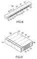
- a stack 56 of the green sheet strips 51a, 51b can finally be obtained as shown in Fig. 8.
- the stack 56 is then baked at the temperature of 1,050 degrees Celsius, for example, in the normal atmosphere.
- the superposed first and second green sheet strips 51a, 51b get integrated based on the baking.
- the stack 56 is cut and divided along the aforementioned centerlines 54, 55.
- Stack segments 57 are obtained in this manner.
- Each stack segment 57 includes a row of the elongated piezoelectric actuators.
- an electrode thin film 58 is formed to extend on the stack segment 57 over the exposed surface of the segment of the uppermost first green sheet strip 51a.
- the electrode thin film 58 may be made of an electrically conductive material such as Pt, for example.
- electrode thin films 59, 61 are formed to spread over the cut or sectional surfaces of the stack segment 57.
- the electrode thin film 59 on one of the cut surfaces is connected to the electrode thin film 58.
- An exposed area is maintained on the stack segment 57 between the electrode thin films 58, 61.
- the first and second elongated piezoelectric actuators 28, 29 are then cut out of the stack segment 57. The cutting is effected along planes 62 intersecting the aforementioned cut surfaces by right angles. The first and second elongated piezoelectric actuators 28, 29 are thus obtained. The first and second elongated piezoelectric actuators 28, 29 are finally adhered to the support plate 24 as well as the flying head slider 21 as described above.
- the present inventors have measured the amount of displacement or movement of the magnetic transducer element 26 as well as the frequency of resonance during the servo control for positioning the magnetic transducer element 26.
- a laser Doppler velocimeter and a servo analyzer were employed in the measurement.
- Nine active piezoelectric transducer layers, namely, nine piezoelectric ceramic layers 35a were established in the individual first and second elongated piezoelectric actuators 28, 29. While the tip ends 28b, 29b of the first and second elongated piezoelectric actuators 28, 29 were adhered to the flying head slider 21, as described above, the base ends 28a, 29a of the first and second elongated piezoelectric actuators 28, 29 were adhered to a ceramic substrate. An electric signal comprising a sine wave of 30V peak-to-peak was supplied to the first and second elongated piezoelectric actuators 28, 29. A displacement amount exceeding 1.0 ⁇ m was demonstrated. The frequency of resonance had exceeded 20kHz.
- Fig. 10 illustrates the first and second elongated piezoelectric actuators 28, 29 according to a second embodiment of the present invention.
- Inactive piezoelectric transducer layers 63 are superposed over the exposed surface of at least one of the first and second inside electrode layers 36, 37 between the base ends 28a, 29a and the tip ends 28b, 29b in the first and second elongated piezoelectric actuators 28, 29.
- the inactive piezoelectric transducer layer 63 may be made of a piezoelectric material such as PNN-PT-PZ, for example.
- a plurality of the first green sheet strips 51a may be superposed on the lower surface of the lowest second green sheet strip 51b or the upper surface of the uppermost second green sheet strip 51b so as to add the inactive piezoelectric transducer layer 63 in the aforementioned method of making the first and second elongated piezoelectric actuators 28, 29. Note that like reference numerals are attached to the structure or component equivalent to those of the aforementioned head suspension assembly 18 and the first and second elongated piezoelectric actuators 28, 29.
- the stack 35 of the piezoelectric ceramic layers 35a namely, the active piezoelectric transducer layers solely get shrunk in the first and second elongated piezoelectric actuators 28, 29, as is apparent from Fig. 11.
- the shrinkage of the active piezoelectric transducer layers serves to pull back the tip ends 28b, 29b toward the base ends 28a, 29a.
- no shrinkage is realized in the inactive piezoelectric transducer layers 63.
- the inactive piezoelectric transducer layer 63 serves to prevent the shrinkage of the active piezoelectric transducer layer, namely, of the stack 35 of the piezoelectric ceramic layers 35a.
- the first and second elongated piezoelectric actuators 28, 29 are allowed to bend when the electric signal is supplied to the first and second elongated piezoelectric actuators 28, 29.
- the bending of the first and second elongated piezoelectric actuators 28, 29 drives the flying head slider 21 to rotate around the rotational axis CR in the same manner as described above.
- the present inventors have also measured the amount of displacement or movement of the magnetic transducer element 26 as well as the frequency of resonance during the servo control for positioning the magnetic transducer element 26 based on this second embodiment, in the same manner as described above.
- Five active piezoelectric transducer layers namely, five piezoelectric ceramic layers 35a were established in the individual first and second elongated piezoelectric actuators 28, 29.
- a displacement amount exceeding 1.0 ⁇ m was demonstrated.
- the frequency of resonance had exceeded 20kHz.
- a displacement amount identical to that of the aforementioned first embodiment could be maintained irrespective of reduction in the number of the active piezoelectric transducer layers.
- a larger change in the attitude of the flying head slider 21 could be realized with few active piezoelectric transducer layers.
- first and second elongated piezoelectric actuators 28, 29 may longitudinally extend all over the flying head slider 21, as shown in Fig. 12, for example.
- the extended length of the first and second elongated piezoelectric actuators 28, 29 in this manner realized a displacement amount exceeding 1.4 ⁇ m.
- the frequency of resonance had still been maintained over a range exceeding 20kHz.
- Fig. 13 illustrates the first and second elongated piezoelectric actuators 28, 29 according to a third embodiment of the present invention.
- additional blocks 64 are attached to the base ends 28a, 29a and the tip ends 28b, 29b of the first and second elongated piezoelectric actuators 28, 29 for reinforcement.
- the first and second elongated piezoelectric actuators 28, 29 of this type allows the first and second elongated piezoelectric actuators 28, 29 to contact the support plate 24 as well as the flying head slider 21 over larger contact areas.
- the first and second elongated piezoelectric actuators 28, 29 can be adhered to the support plate 24 as well as the flying head slider 21 over larger areas.
- the bonding strength can be improved between the first and second elongated piezoelectric actuators 28, 29 and the support plate 24 as well as the flying head slider 21. Still, a displacement amount over 1.0 ⁇ m can be maintained. The frequency of resonance can be raised over 20kHz.
- the first and second elongated piezoelectric actuators 28, 29 may be punched out of the stack segment 57 according to a predetermined shape so as to form the additional blocks 64 in the aforementioned method of making the first and second elongated piezoelectric actuators 28, 29. Note that like reference numerals are attached to the structure or component equivalent to those of the aforementioned head suspension assembly 18 and the first and second elongated piezoelectric actuators 28, 29.
Abstract
Description
- The present invention relates to a recording medium drive, for managing recordation or storage of information in a recording medium, and a head assembly therefor.
- As disclosed in Japanese Patent Application Publication 11-273041, for example, a well-known head assembly sometimes includes piezoelectric actuators interposed between a head slider and a head suspension. A first common attachment piece is fixed to the head suspension in the head assembly. A pair of parallel piezoelectric actuators extend from the first common attachment piece toward the head slider. The tip ends of the respective piezoelectric actuators are coupled to a second common attachment piece fixed to the head slider. The head slider swings around the first common attachment piece in response to expansion and shrinkage of the piezoelectric actuators. The swinging movement of the head slider thus realizes a fine or smaller displacement of the head slider in the radial direction of a magnetic or hard disk. This fine displacement of the head slider enables a read/write head on the head slider to follow recording tracks on the magnetic disk with higher accuracy.
- An electric or servo signal is supplied to the piezoelectric actuators for servo controlling the swinging movement of the head slider. If the frequency of the servo signal gets higher, the head slider can be positioned on the recording tracks at a still higher accuracy. Positioning the read/write head with improved accuracy leads to an increased density of recordation over the magnetic disk.
- The head slider and the piezoelectric actuator establish a vibration system. Accordingly, if the frequency of the servo signal coincides with the natural frequency of the vibration system, the head slider suffers from abnormal displacement, namely, resonance. In this case, the position of the head slider cannot be controlled. If the natural frequency of the vibration system is raised, the frequency range of the servo signal can be expanded.
- Accordingly, it is desirable to provide a head assembly that allows expansion of the frequency range of an electric signal supplied to a piezoelectric actuator.
- According to an embodiment of the present invention, there is provided a head assembly comprising: a support member, a head slider, and a piezoelectric actuator set disposed between the support member and the head slider for establishing a standard attitude of the head slider when supply of an electric signal is cut off, wherein said piezoelectric actuator set generates a couple changing an attitude of the head slider around a rotational axis only in a predetermined direction.
- A head assembly embodying the present invention utilizes the rotation of the head slider so as to accomplish a fine or smaller movement of a head or transducer element. The moment of inertia can be reduced in the head slider during rotation as compared with the case where the head slider is moved in a swinging manner. Only a smaller moment acts on individual piezoelectric actuators of the piezoelectric actuator set, so that the natural frequency can be raised in the vibration system comprising the head slider and the piezoelectric actuator set. The frequency of the electric signal or servo signal can be set over a wider frequency range.
- Moreover, the head assembly simply changes the attitude of the head slider around the rotational axis only in the predetermined direction from the standard attitude. As compared with the case where the attitude of the head slider is changed in at least two directions from the standard attitude, it is possible to simplify the structure of the piezoelectric actuators of the piezoelectric actuator set. Since the piezoelectric actuator set may include few piezoelectric actuators, it is possible toreduce the number of electric terminals, such as golden balls, connected to the piezoelectric actuator set. The electric signal can reliably be supplied to the piezoelectric actuator set with a simplified structure.
- For example, the piezoelectric actuator set may include: a first elongated piezoelectric actuator extending in a first direction, a base end of the first elongated piezoelectric actuator being attached to the support member, a tip end of the first elongated piezoelectric actuator being attached to the head slider; and a second elongated piezoelectric actuator extending in a second direction antiparallel to the first direction, a base end of the second elongated piezoelectric actuator being attached to the support member, a tip end of the second elongated piezoelectric actuator being attached to the head slider. In particular, the first elongated piezoelectric actuator is allowed to shrink in a first direction upon supply of the electric signal, while the second elongated piezoelectric actuator is allowed to shrink in a second direction, antiparallel to the first direction, upon supply of the electric signal. The head assembly of this type solely utilizes a pair of the elongated piezoelectric actuators so as to realize the rotation of the head slider. The structure of the head assembly can be simplified. The first and second elongated piezoelectric actuators may be located symmetric to each other around the rotational axis so as to realize the generation of a couple.
- The head assembly may further comprise: first outside electrodes connected to the base ends of the first and second elongated piezoelectric actuators, respectively; and second outside electrodes extending from the tip ends toward the base ends along surfaces of the first and second elongated piezoelectric actuators, respectively. The head assembly of this type allows the first and second outside electrodes to be located only near the base ends of the respective elongated piezoelectric actuators. Terminals such as golden balls can thus easily be connected or bonded to the first and second elongated piezoelectric actuators. The electric signal can be supplied to the first and second elongated piezoelectric actuators with a simple structure.
- Each of the first and second elongated piezoelectric actuators may comprise: first inside electrode layers connected to the first outside electrode at outer ends of the first inside electrode layers near the base end of the elongated piezoelectric actuator, said first inside electrode layers extending from the outer ends toward the tip end of the elongated piezoelectric actuator; second inside electrode layers each disposed between adjacent ones of the first inside electrode layers and connected to the second outside electrode at outer ends of the second inside electrode layers near the tip end of the elongated piezoelectric actuator, said second inside electrode layers extending from the outer ends toward the base end of the elongated piezoelectric actuator; and active piezoelectric transducer layers interposed between the first and second inside electrode layers. When the electric signal is supplied to the active piezoelectric transducer layers, the active piezoelectric transducer layers shrink in the d31 direction, perpendicular to the direction of the electric signal, based on a so-called lateral effect. Specifically, the active piezoelectric transducer layers shrink along the first and second inside electrode layers. The shrinkage of the piezoelectric actuators is thus realized. The amount of the shrinkage depends upon the intensity of the applied voltage. The active piezoelectric transducer layer may be made from a piezoelectric material such as PNN-PT-PZ, for example.
- Each of the first and second elongated piezoelectric actuators may further comprise an inactive piezoelectric transducer layer superposed over an outer surface of at least one of the first and second inside electrode layers between the trailing and tip ends of the elongated piezoelectric actuator. The active piezoelectric transducer layers solely shrink in the first and second elongated piezoelectric actuators upon supply of the electric signal. The inactive piezoelectric transducer layer serves to prevent the active piezoelectric transducer layers from shrinkage. As a result, the elongated piezoelectric actuators of this type are allowed to bend upon supply of the electric signal. The bending and the shrinkage cooperate to generate the aforementioned couple. The inactive piezoelectric transducer layer may be made from the material identical to that of the active piezoelectric transducer layer.
- The head assembly of the type described above may be incorporated in a magnetic disk drive such as hard disk drive (HDD), and other types of recording disk drives.
- Reference will now be made, by way of example, to the accompanying drawings, in which:-
- Fig. 1 is a plan view schematically illustrating the structure of a hard disk drive (HDD) as an example of a recording medium drive;
- Fig. 2 is an enlarged partial perspective view illustrating the structure of a head suspension assembly in detail;
- Fig. 3 is an enlarged plan view of a support plate for illustrating the location of the first and second elongated piezoelectric actuators;
- Fig. 4 is an enlarged perspective view schematically illustrating the structure of an elongated piezoelectric actuator according to a first embodiment of the present invention;
- Fig. 5 is an enlarged plan view of the support plate for schematically illustrating the movement of the flying head slider;
- Fig. 6 is an enlarged perspective view schematically illustrating the structure of an elongated piezoelectric actuator according to a modification of the first embodiment;
- Fig. 7 is a perspective view schematically illustrating first and second green sheet strips employed to make the elongated piezoelectric actuators;
- Fig. 8 is a perspective view schematically illustrating a stack of the green sheet strips employed to make the elongated piezoelectric actuators;
- Fig. 9 is an enlarged perspective view illustrating electrode thin films formed on a stack segment;
- Fig. 10 is an enlarged perspective view of the support plate for schematically illustrating the structure of an elongated piezoelectric actuator according to a second embodiment of the present invention;
- Fig. 11 is an enlarged plan view of the support plate for schematically illustrating the movement of the elongated piezoelectric actuators according to the second embodiment;
- Fig. 12 is an enlarged plan view of the support plate for schematically illustrating the structure of an elongated piezoelectric actuator according to a modification of the third embodiment; and
- Fig. 13 is an enlarged plan view of the support plate for schematically illustrating the structure of an elongated piezoelectric actuator according to a third embodiment of the present invention.
-
- Fig. 1 schematically illustrates the inner structure of a hard disk drive (HDD) 11 as an example of a recording medium drive or storage device. The HDD 11 includes a box-shaped
primary enclosure 12 defining an inner space of a flat parallelepiped, for example. At least one magnetic recording disk 13 is accommodated in the inner space within theprimary enclosure 12. The magnetic recording disk 13 is mounted on a driving shaft of aspindle motor 14. Thespindle motor 14 is used to drive the magnetic recording disk 13 for rotation at revolution speeds that are as high as 7,200rpm or 10,000rpm, for example. A cover, not shown, is coupled to theprimary enclosure 12 so as to define the closed inner space between theprimary enclosure 12 and itself. - A
carriage 16 is also accommodated in the inner space of theprimary enclosure 12 for swinging movement about avertical support shaft 15. Thecarriage 16 includes arigid swinging arm 17 extending in the horizontal direction from thevertical support shaft 15, and ahead suspension assembly 18 attached to the front or tip end of the swingingarm 17. Thehead suspension assembly 18 includes anelastic head suspension 19 extending forward from the front end of the swingingarm 17. As previously-proposed, a flyinghead slider 21 is supported on thehead suspension 19 near the front end thereof. Thehead suspension 19 functions as a support member according to an embodiment of the present invention. - The
head suspension 19 serves to urge the flyinghead slider 21 toward the surface of the magnetic recording disk 13. When the magnetic recording disk 13 rotates, the flyinghead slider 21 receives airflow generated along the rotating magnetic recording disk 13. The airflow serves to generate a lift on the flyinghead slider 21. The flyinghead slider 21 is thus allowed to keep flying above the surface of the magnetic recording disk 13 during rotation of the magnetic recording disk 13 at a higher stability established by the balance between the lift and the urging force of thehead suspension 19. - When the
carriage 16 is driven to swing about thesupport shaft 15 during flight of the flyinghead slider 21, the flyinghead slider 21 is allowed to cross the recording tracks defined on the magnetic recording disk 13 in the radial direction of the magnetic recording disk 13. This radial movement serves to position the flyinghead slider 21 right above a target recording track on the magnetic recording disk 13. In this case, anelectromagnetic actuator 22 such as a voice coil motor (VCM) can be employed to realize the swinging movement of thecarriage 16, for example. As previously-proposed, in the case where two or more magnetic recording disks 13 are incorporated within the inner space of theprimary enclosure 12, a pair of the elastichead suspension assemblies 18 are mounted on a singlecommon swinging arm 17 between the adjacent magnetic recording disks 13. - As shown in Fig. 2, a
support plate 24 is punched out at the front end of thehead suspension 19 in thehead suspension assembly 18. Thesupport plate 24 is allowed to change its attitude based on the action of a so-calledgimbal spring 25. The flyinghead slider 21 is received on the surface of thesupport plate 24. Amagnetic transducer element 26 is mounted on the flyinghead slider 21. Themagnetic transducer element 26 may include a write element such as a thin film magnetic head utilized to write magnetic information onto the magnetic recording disk 13, and a read element such as a giant magnetoresistive (GMR) element and a tunnel-junction magnetoresistive (TMR) element utilized to read magnetic information from the magnetic recording disk 13, for example. - Piezoelectric actuator set 27 is disposed between the flying
head slider 21 and thesupport plate 24. The piezoelectric actuator set 27 includes a first elongatedpiezoelectric actuator 28. The first elongatedpiezoelectric actuator 28 is fixed to thesupport plate 24 at thebase end 28a. The first elongatedpiezoelectric actuator 28 is designed to extend from thebase end 28a in a first direction DR1. The tip end 28b of the first elongatedpiezoelectric actuator 28 in the first direction DR1 is fixed to the flyinghead slider 21. Likewise, the piezoelectric actuator set 27 includes a second elongatedpiezoelectric actuator 29. The second elongatedpiezoelectric actuator 29 is fixed to thesupport plate 24 at thebase end 29a. The second elongatedpiezoelectric actuator 29 is designed to extend from thebase end 29a in a second direction DR2. Thetip end 29b of the second elongatedpiezoelectric actuator 29 in the second direction DR2 is fixed to the flyinghead slider 21. The second direction DR2 is set antiparallel to the first direction DR1. An adhesive including an epoxy resin may be employed to fix the first and second elongatedpiezoelectric actuators support plate 24 as well as the flyinghead slider 21, for example. - As is apparent from Fig. 3, the first and second elongated
piezoelectric actuators head slider 21. Accordingly, when the first and second elongatedpiezoelectric actuators head slider 21 thus receives the driving force for rotation around the rotational axis CR based on the generated couple. The attitude of the flyinghead slider 21 can be changed around the rotational axis CR based on the application of the driving force. - As shown in Fig. 4, the first elongated
piezoelectric actuator 28 according to a first embodiment of the present invention includes a first piezoelectricceramic block 31 forming thebase end 28a of the first elongatedpiezoelectric actuator 28, and a second piezoelectricceramic block 32 likewise forming the tip end 28b of the first elongatedpiezoelectric actuator 28. A firstoutside electrode layer 33 is coupled to the end surface of thebase end 28a of the first elongatedpiezoelectric actuator 28, namely, an exposed surface of the first piezoelectricceramic block 31. Likewise, a secondoutside electrode layer 34 is coupled to the end surface of the tip end 28b of the first elongatedpiezoelectric actuator 28, namely, an exposed surface of the second piezoelectricceramic block 32. The first and second outside electrode layers 33, 34 may be made of an electrically conductive metallic material such as Pt, for example. - A
stack 35 of piezoelectricceramic layers 35a is interposed between the first and second piezoelectric ceramic blocks 31, 32. First and second inside electrode layers 36, 37 are alternately sandwiched between the adjacent ones of the piezoelectricceramic layers 35a in thestack 35. The first inside electrode layers 36 are designed to penetrate through the first piezoelectricceramic block 31 so as to reach the outer surface of the first piezoelectricceramic block 31. In this manner, the outer ends of the first inside electrode layers 36 are connected to the firstoutside electrode layer 33. The first inside electrode layers 36 are kept outside the second piezoelectricceramic block 32. Likewise, the second inside electrode layers 37 are designed to penetrate through the second piezoelectricceramic block 32 so as to reach the outer surface of the second piezoelectricceramic block 32. The outer ends of the second inside electrode layers 37 are thus connected to the secondoutside electrode layer 34. The second inside electrode layers 37 are kept outside the first piezoelectricceramic block 31. The piezoelectricceramic layers 35a between the first and second inside electrode layers 36, 37 correspond to active piezoelectric transducer layers according to an embodiment of the present invention. The first and second piezoelectric ceramic blocks 31, 32, as well as the piezoelectricceramic layers 35a, may be made of a piezoelectric material such as PNN-PT-PZ, for example. The first and second inside electrode layers 36, 37 may be made of an electrically conductive material such as Pt, for example. - A
surface electrode layer 38 is coupled to the outer surface of thestack 35 in the first elongatedpiezoelectric actuator 28. Thesurface electrode layer 38 is designed to extend from the outer surface of the second piezoelectricceramic block 32 near the tip end 28b toward thebase end 28a in the first elongatedpiezoelectric actuator 28. Thesurface electrode layer 38 may serve to hold the outermost piezoelectricceramic layer 35a against the firstinside electrode layer 36. Thesurface electrode layer 38 is connected to the secondoutside electrode layer 34 at one end. The other end of thesurface electrode layer 38 is terminated at a position spaced from the firstoutside electrode layer 33. Specifically, an electric connection is prohibited between thesurface electrode layer 38 and the firstoutside electrode layer 33. Thesurface electrode layer 38 and the secondoutside electrode layer 34 thus correspond to a second outside electrode according to an embodiment of the present invention. Thesurface electrode layer 38 may be made of an electrically conductive material such as Pt, for example. - The first
outside electrode layer 33 and thesurface electrode layer 38 are designed to stand on the surface of thesupport plate 24 at the periphery of the first piezoelectricceramic block 31. An electrically conductive terminal 39 such as a golden ball, for example, is connected to the exposed surface of the firstoutside electrode layer 33. A solder paste may be employed to attach the electrically conductive terminal 39 to the firstoutside electrode layer 33. Likewise, an electricallyconductive terminal 41, such as a golden ball, is connected to thesurface electrode layer 38 at the periphery of the first piezoelectricceramic block 31. - On the other hand, electrically conductive
terminal pads support plate 24. The electricallyconductive terminals terminal pads terminal pads conductive wiring pattern 44 extending over the surface of thehead suspension 19. The electricallyconductive wiring pattern 44 may be connected to a controller chip, not shown, incorporated within theHDD 11. - Assume that an electric signal of a predetermined voltage is supplied to the first
piezoelectric actuator 28 through the electricallyconductive terminals ceramic layer 35a is allowed to receive the field intensity, of approximately 1kV/mm, for example, between the first and second inside electrode layers 36, 37. The applied voltage serves to generate polarization, corresponding to the direction of the applied voltage, in the individual piezoelectricceramic layer 35a. When an electric signal is further supplied to the individual piezoelectricceramic layer 35a subsequent to the polarization, the piezoelectricceramic layer 35a shrinks in the d31 direction, which is a direction perpendicular to the direction of the polarization, based on a so-called lateral effect. The amount of shrinkage depends upon the intensity of the applied voltage. In this manner, the shrinkage of the first elongatedpiezoelectric actuator 28 can be realized. It should be noted that the second elongatedpiezoelectric actuator 29 may have the structure identical to that of the first elongatedpiezoelectric actuator 28. - When no electric signal is supplied to the piezoelectric actuator set 27, the piezoelectric actuator set 27 serves to establish the standard attitude of the flying
head slider 21 on thesupport plate 24, as shown in Fig. 3, for example. When the voltage is applied to the first and second elongatedpiezoelectric actuators piezoelectric actuators piezoelectric actuators piezoelectric actuators head slider 21 around the rotational axis CR only in a predetermined direction from the standard attitude. In this manner, the attitude of the flyinghead slider 21 can be changed on thesupport plate 24. When the supply of the electric signal is terminated, the first and second elongatedpiezoelectric actuators head slider 21 thus reverts to the standard attitude around the rotational axis CR. - Now, assume that the
magnetic transducer element 26 on the flyinghead slider 21 is to be positioned on a specific recording track on the magnetic recording disk 13. In this case, the controller chip of theHDD 11 is set to supply the electric signal in a range between 0V and 30V, for example, to the first and second elongatedpiezoelectric actuators piezoelectric actuators piezoelectric actuators magnetic transducer element 26 is allowed to move or shift on thesupport plate 24 in the lateral direction perpendicular to the recording track by the maximum linear amount or stroke of approximately 1.0µm. - Prior to commencement of positioning the
magnetic transducer element 26, the electric signal of 15V is supplied to the piezoelectric actuator set 27. Accordingly, themagnetic transducer element 26 is moved on thesupport plate 24 by a half of the maximum stroke, namely, the stroke of 0.5µm, as shown in Fig. 5, for example. Thereafter, themagnetic transducer element 26 is roughly positioned above the target recording track based on the swinging movement of thecarriage 16 or swingingarm 17. - When the
magnetic transducer element 26 starts to follow the target recording track, the controller chip supplies the electric signal to the piezoelectric actuator set 27 based on the servo control. When the voltage of the electric signal is reduced below 15V, the first and second elongatedpiezoelectric actuators head slider 21 is thus driven to rotate around the rotational axis CR in the counterclockwise direction CL1. This rotation of the flyinghead slider 21 allows themagnetic transducer element 26 to move in the radial direction of the magnetic recording disk 13. When the voltage of the electric signal is raised over 15V, the first and second elongatedpiezoelectric actuators head slider 21 is thus driven to rotate around the rotational axis CR in the clockwise direction CL2. This rotation of the flyinghead slider 21 allows themagnetic transducer element 26 to move in the opposite direction along the radial direction of the magnetic recording disk 13. In this manner, themagnetic transducer element 26 is forced to follow the target recording track at a higher accuracy. - The
head suspension assembly 18 utilizes the rotation of the flyinghead slider 21 so as to accomplish a fine or smaller movement of themagnetic transducer element 26. The moment of inertia can be reduced in the flyinghead slider 21 during rotation. Only a smaller moment acts on the individual elongatedpiezoelectric actuator head slider 21 and the piezoelectric actuator set 27. The frequency of the electric signal or servo signal can be set over a wider frequency range. To the contrary, in the case where the flyinghead slider 21 is moved based on a swinging movement, the overall mass of the flyinghead slider 21 contributes to generation of the moment of inertia. In addition, the distance is increased between the center of mass and the center of trajectory. A larger moment of inertia is forced to act on the flyinghead slider 21. The servo signal tends to generate the resonance at a relatively lower frequency range. - Moreover, the
head suspension assembly 18 solely utilizes a pair of the elongatedpiezoelectric actuators head slider 21. Thus, the structure of thehead suspension assembly 18 can be simplified. Additionally, the electricallyconductive terminals piezoelectric actuators piezoelectric actuators - The surface electrode layers 38 of the first and second elongated
piezoelectric actuators support plate 24 in the aforementionedhead suspension assembly 18, as shown in Fig. 6. In this case, thesurface electrode layer 38 is superposed on the electricallyconductive terminal pad 43 on thesupport plate 24 at the periphery of the first piezoelectricceramic block 31. An electrically conductive adhesive may be employed to fix thesurface electrode layer 38 on the electricallyconductive terminal pad 43, for example. The electrically conductive adhesive realizes the physical connection between thesupport plate 24 and the first and second elongatedpiezoelectric actuators surface electrode layer 38 and the electricallyconductive terminal pad 43. The first and second elongatedpiezoelectric actuators head slider 21 and the first and second inside electrode layers 36, 37 as well as the surface electrode layers 38. - Next, a brief description will be given of a method of making the elongated
piezoelectric actuators green sheet strips green sheet strips green sheet strips green sheet strips Thin films 52 of an electrically conductive material, such as Pt, are added to the surface of the individual secondgreen sheet strip 51b. Screen printing may be employed to form thethin films 52. - Exposed areas are kept on the second
green sheet strip 51b between the adjacent ones of thethin films 52. The exposed area is allowed to completely cross the secondgreen sheet strip 51b in the lateral direction perpendicular to the longitudinal direction of the secondgreen sheet strip 51b. Thecenterlines 54 can be defined on the individualthin films 52 in the lateral direction. Thecenterlines 55 can also be defined on the individual exposed areas. The space L between thecenterlines piezoelectric actuators - The second green sheet strips 51b are then sequentially superposed relative to one another. The number of the second
green sheet strip 51b may be set dependent upon the amount of the intended shrinkage in the first and second elongatedpiezoelectric actuators centerlines 55 of the exposed areas on the upper second green sheet strips 51b are aligned with thecenterlines 54 of thethin films 52 on the lower second green sheet strips 51b. One or more firstgreen sheet strips 51a may be interposed between the upper and lower second green sheet strips 51b. The number of the interposed firstgreen sheet strip 51a may be set dependent upon the intended thickness of the active piezoelectric transducer layer for the first and second elongatedpiezoelectric actuators green sheet strips 51a may also be superposed over the lower surface of the lowest secondgreen sheet strip 51b and/or the upper surface of the uppermost second green sheet strips 51b. Astack 56 of thegreen sheet strips - The
stack 56 is then baked at the temperature of 1,050 degrees Celsius, for example, in the normal atmosphere. The superposed first and secondgreen sheet strips stack 56 is cut and divided along theaforementioned centerlines segments 57 are obtained in this manner. Eachstack segment 57 includes a row of the elongated piezoelectric actuators. As shown in Fig. 9, an electrodethin film 58 is formed to extend on thestack segment 57 over the exposed surface of the segment of the uppermost firstgreen sheet strip 51a. The electrodethin film 58 may be made of an electrically conductive material such as Pt, for example. Likewise, electrodethin films 59, 61 are formed to spread over the cut or sectional surfaces of thestack segment 57. The electrodethin film 59 on one of the cut surfaces is connected to the electrodethin film 58. An exposed area is maintained on thestack segment 57 between the electrodethin films 58, 61. - The first and second elongated
piezoelectric actuators stack segment 57. The cutting is effected alongplanes 62 intersecting the aforementioned cut surfaces by right angles. The first and second elongatedpiezoelectric actuators piezoelectric actuators support plate 24 as well as the flyinghead slider 21 as described above. - The present inventors have measured the amount of displacement or movement of the
magnetic transducer element 26 as well as the frequency of resonance during the servo control for positioning themagnetic transducer element 26. A laser Doppler velocimeter and a servo analyzer were employed in the measurement. Nine active piezoelectric transducer layers, namely, nine piezoelectricceramic layers 35a were established in the individual first and second elongatedpiezoelectric actuators piezoelectric actuators head slider 21, as described above, the base ends 28a, 29a of the first and second elongatedpiezoelectric actuators piezoelectric actuators - Fig. 10 illustrates the first and second elongated
piezoelectric actuators piezoelectric actuators piezoelectric transducer layer 63 may be made of a piezoelectric material such as PNN-PT-PZ, for example. Since no path for electric signals is established in the inactivepiezoelectric transducer layer 63 based on the inside electrode layers 36, 37, shrinkage and elongation are prevented in thepiezoelectric transducer layer 63. A plurality of the firstgreen sheet strips 51a may be superposed on the lower surface of the lowest secondgreen sheet strip 51b or the upper surface of the uppermost secondgreen sheet strip 51b so as to add the inactivepiezoelectric transducer layer 63 in the aforementioned method of making the first and second elongatedpiezoelectric actuators head suspension assembly 18 and the first and second elongatedpiezoelectric actuators - When the electric signal is supplied to the elongated
piezoelectric actuators stack 35 of the piezoelectricceramic layers 35a, namely, the active piezoelectric transducer layers solely get shrunk in the first and second elongatedpiezoelectric actuators piezoelectric transducer layer 63 serves to prevent the shrinkage of the active piezoelectric transducer layer, namely, of thestack 35 of the piezoelectricceramic layers 35a. The first and second elongatedpiezoelectric actuators piezoelectric actuators piezoelectric actuators head slider 21 to rotate around the rotational axis CR in the same manner as described above. - The present inventors have also measured the amount of displacement or movement of the
magnetic transducer element 26 as well as the frequency of resonance during the servo control for positioning themagnetic transducer element 26 based on this second embodiment, in the same manner as described above. Five active piezoelectric transducer layers, namely, five piezoelectricceramic layers 35a were established in the individual first and second elongatedpiezoelectric actuators head slider 21 could be realized with few active piezoelectric transducer layers. - Here, the first and second elongated
piezoelectric actuators head slider 21, as shown in Fig. 12, for example. The extended length of the first and second elongatedpiezoelectric actuators - Fig. 13 illustrates the first and second elongated
piezoelectric actuators additional blocks 64 are attached to the base ends 28a, 29a and the tip ends 28b, 29b of the first and second elongatedpiezoelectric actuators piezoelectric actuators piezoelectric actuators support plate 24 as well as the flyinghead slider 21 over larger contact areas. The first and second elongatedpiezoelectric actuators support plate 24 as well as the flyinghead slider 21 over larger areas. Accordingly, the bonding strength can be improved between the first and second elongatedpiezoelectric actuators support plate 24 as well as the flyinghead slider 21. Still, a displacement amount over 1.0µm can be maintained. The frequency of resonance can be raised over 20kHz. The first and second elongatedpiezoelectric actuators stack segment 57 according to a predetermined shape so as to form theadditional blocks 64 in the aforementioned method of making the first and second elongatedpiezoelectric actuators head suspension assembly 18 and the first and second elongatedpiezoelectric actuators
Claims (18)
- A head assembly comprising:wherein said piezoelectric actuator set generates a couple changing an attitude of the head slider around a rotational axis only in a predetermined direction.a support member;a head slider; anda piezoelectric actuator set disposed between the support member and the head slider for establishing a standard attitude of the head slider when supply of an electric signal is cut off;
- The head assembly according to claim 1, wherein said piezoelectric actuator set includes:a first elongated piezoelectric actuator shrinking in a first direction upon supply of the electric signal; anda second elongated piezoelectric actuator shrinking in a second direction, antiparallel to the first direction, upon supply of the electric signal.
- The head assembly according to claim 1, wherein said piezoelectric actuator set includes:a first elongated piezoelectric actuator extending in a first direction, a base end of the first elongated piezoelectric actuator being attached to the support member, a tip end of the first elongated piezoelectric actuator being attached to the head slider; anda second elongated piezoelectric actuator extending in a second direction antiparallel to the first direction, a base end of the second elongated piezoelectric actuator being attached to the support member, a tip end of the second elongated piezoelectric actuator being attached to the head slider.
- The head assembly according to claim 2 or 3, wherein said first and second elongated piezoelectric actuators are located symmetric to each other around the rotational axis.
- The head assembly according to claim 2, 3 or 4, further comprising:first outside electrodes connected to the base ends of the first and second elongated piezoelectric actuators, respectively; andsecond outside electrodes extending from the tip ends toward the base ends along surfaces of the first and second elongated piezoelectric actuators, respectively.
- The head assembly according to claim 5, wherein each of said first and second elongated piezoelectric actuators comprises:first inside electrode layers connected to the first outside electrode at outer ends of the first inside electrode layers near the base end of the elongated piezoelectric actuator, said first inside electrode layers extending from the outer ends toward the tip end of the elongated piezoelectric actuator;second inside electrode layers each disposed between adjacent ones of the first inside electrode layers and connected to the second outside electrode at outer ends of the second inside electrode layers near the tip end of the elongated piezoelectric actuator, said second inside electrode layers extending from the outer ends toward the base end of the elongated piezoelectric actuator; andactive piezoelectric transducer layers interposed between the first and second inside electrode layers.
- The head assembly according to claim 6, wherein said active piezoelectric transducer layer is made from PNN-PT-PZ.
- The head assembly according to claim 6 or 7, wherein each of the first and second elongated piezoelectric actuators further comprises an inactive piezoelectric transducer layer superposed over an outer surface of at least one of the first and second inside electrode layers between the trailing and tip ends of the elongated piezoelectric actuator.
- The head assembly according to claim 8, wherein said inactive piezoelectric transducer layer is made from PNN-PT-PZ.
- A recording medium drive comprising:wherein said piezoelectric actuator set generates a couple changing an attitude of the head slider around a rotational axis only in a predetermined direction.a swinging arm;a head suspension extending forward from a front end of the swinging arm;a head slider; anda piezoelectric actuator set disposed between the head suspension and the head slider for establishing a standard attitude of the head slider when supply of an electric signal is cut off;
- The recording medium drive according to claim 10, wherein said piezoelectric actuator set includes:a first elongated piezoelectric actuator shrinking in a first direction upon supply of the electric signal; anda second elongated piezoelectric actuator shrinking in a second direction, antiparallel to the first direction, upon supply of the electric signal.
- The recording medium drive according to claim 10, wherein said piezoelectric actuator set includes:a first elongated piezoelectric actuator extending in a first direction, a base end of the first elongated piezoelectric actuator being attached to the head suspension, a tip end of the first elongated piezoelectric actuator being attached to the head slider; anda second elongated piezoelectric actuator extending in a second direction antiparallel to the first direction, a base end of the second elongated piezoelectric actuator being attached to the head suspension, a tip end of the second elongated piezoelectric actuator being attached to the head slider.
- The recording medium drive according to claim 11 or 12, wherein said first and second elongated piezoelectric actuators are located symmetric to each other around the rotational axis.
- The recording medium drive according to claim 11, 12 or 13, further comprising:first outside electrodes connected to the base ends of the first and second elongated piezoelectric actuators, respectively; andsecond outside electrodes extending from the tip ends toward the base ends along surfaces of the first and second elongated piezoelectric actuators, respectively.
- The recording medium drive according to claim 14, wherein each of said first and second elongated piezoelectric actuators comprises:first inside electrode layers connected to the first outside electrode at outer ends of the first inside electrode layers near the base end of the elongated piezoelectric actuator, said first inside electrode layers extending from the outer ends toward the tip end of the elongated piezoelectric actuator;second inside electrode layers each disposed between adjacent ones of the first inside electrode layers and connected to the second outside electrode at outer ends of the second inside electrode layers near the tip end of the elongated piezoelectric actuator, said second inside electrode layers extending from the outer ends toward the base end of the elongated piezoelectric actuator; andactive piezoelectric transducer layers interposed between the first and second inside electrode layers.
- The recording medium drive according to claim 15, wherein said active piezoelectric transducer layer is made from PNN-PT-PZ.
- The recording medium drive according to claim 15 or 16, wherein each of the first and second elongated piezoelectric actuators further comprises an inactive piezoelectric transducer layer superposed over an outer surface of at least one of the first and second inside electrode layers between the trailing and tip ends of the elongated piezoelectric actuator.
- The recording medium drive according to claim 17, wherein said inactive piezoelectric transducer layer is made from PNN-PT-PZ.
Applications Claiming Priority (2)
| Application Number | Priority Date | Filing Date | Title |
|---|---|---|---|
| JP2001318985 | 2001-10-17 | ||
| JP2001318985A JP2003123416A (en) | 2001-10-17 | 2001-10-17 | Head assembly and recording medium driver |
Publications (2)
| Publication Number | Publication Date |
|---|---|
| EP1304683A2 true EP1304683A2 (en) | 2003-04-23 |
| EP1304683A3 EP1304683A3 (en) | 2006-12-27 |
Family
ID=19136602
Family Applications (1)
| Application Number | Title | Priority Date | Filing Date |
|---|---|---|---|
| EP02251761A Withdrawn EP1304683A3 (en) | 2001-10-17 | 2002-03-13 | Recording medium drive and head assembly therefor |
Country Status (5)
| Country | Link |
|---|---|
| US (1) | US6617763B2 (en) |
| EP (1) | EP1304683A3 (en) |
| JP (1) | JP2003123416A (en) |
| KR (1) | KR100772071B1 (en) |
| CN (1) | CN1306477C (en) |
Cited By (1)
| Publication number | Priority date | Publication date | Assignee | Title |
|---|---|---|---|---|
| EP1391882A1 (en) * | 2002-08-23 | 2004-02-25 | Hitachi Global Storage Technologies Netherlands B.V. | Electrostatic mircroactuator with electrically isolated moveable portion and associated drive circuitry |
Families Citing this family (44)
| Publication number | Priority date | Publication date | Assignee | Title |
|---|---|---|---|---|
| JP4146127B2 (en) * | 2002-01-16 | 2008-09-03 | セイコーインスツル株式会社 | Piezoelectric actuator and electronic device including the same |
| JP4566529B2 (en) * | 2003-07-11 | 2010-10-20 | 富士通株式会社 | Fine movement actuator and recording medium driving device |
| EP1748761A4 (en) * | 2004-05-27 | 2011-10-12 | Dexcel Pharma Technologies Ltd | Localized controlled absorption of statins in the gastrointestinal tract for achieving high blood levels of statins |
| CN100426412C (en) * | 2004-06-05 | 2008-10-15 | 新科实业有限公司 | HGA with flying altitude regulator, hard disc driver and producing method thereof |
| CN100411014C (en) * | 2004-08-30 | 2008-08-13 | 新科实业有限公司 | Micro-driver, magnetic head tabs assembly and magnetic disk driver using it |
| US7312956B2 (en) * | 2004-09-08 | 2007-12-25 | Sae Magnetics (H.K.) Ltd | Micro-actuator, head gimbal assembly, and disk drive unit with the same |
| US7298593B2 (en) * | 2004-10-01 | 2007-11-20 | Sae Magnetics (H.K.) Ltd. | Micro-actuator including a leading beam pivot part, head gimbal assembly and disk drive unit with the same |
| US7551386B2 (en) * | 2004-10-18 | 2009-06-23 | Sae Magnetics (H.K.) Ltd. | Head gimbal assembly with flying height controller, disk drive unit using the same, and flying height adjusting method and system thereof |
| US20060098347A1 (en) * | 2004-11-10 | 2006-05-11 | Sae Magnetics (H.K.) Ltd. | Micro-actuator, head gimbal assembly and disk drive unit with the same |
| CN1797550A (en) * | 2004-12-30 | 2006-07-05 | 新科实业有限公司 | Composition of micro driver unit, vibration damper, fold piece set of magnetic head, and disc drive unit |
| US7433159B2 (en) * | 2005-01-27 | 2008-10-07 | Sae Magnetics (H.K.) Ltd. | Micro-actuator unit, head gimbal assembly, and disk drive unit with vibration canceller |
| US7280319B1 (en) | 2005-01-31 | 2007-10-09 | Western Digital Technologies, Inc. | Suspension assembly with piezoelectric microactuators electrically connected to a folded flex circuit segment |
| CN1828727A (en) * | 2005-02-28 | 2006-09-06 | 新科实业有限公司 | Micro driver and its magnetic head tab combination and magnetic disk driving unit |
| CN1828726B (en) * | 2005-02-28 | 2010-04-28 | 新科实业有限公司 | Rotatable piezo-electric micro driver and its magnetic head tab combination and magnetic disk driving unit |
| US7408745B2 (en) * | 2005-05-10 | 2008-08-05 | Sae Magnetics (H.K.) Ltd. | Sway-type micro-actuator with slider holding arms for a disk drive head gimbal assembly |
| US7277258B2 (en) * | 2005-06-21 | 2007-10-02 | Hitachi Global Storage Technologies Netherlands B.V. | Dual-stage actuator disk drive with optimal location of the movable portion of the secondary actuator |
| US7535680B2 (en) * | 2005-06-29 | 2009-05-19 | Sae Magnetics (H.K.) Ltd. | Micro-actuator with integrated trace and bonding pad support |
| US20070000110A1 (en) * | 2005-06-29 | 2007-01-04 | Sae Magnetics (H.K.) Ltd. | Method for treating PZT element, PZT micro-actuator, head gimbal assembly and disk drive unit with treated PZT micro-actuator |
| US7535681B2 (en) * | 2005-07-29 | 2009-05-19 | Sae Magentics (H.K.) Ltd. | Micro-actuator including side arms having back-turned extensions, head gimbal assembly and disk drive unit with the same |
| US20070070552A1 (en) * | 2005-09-27 | 2007-03-29 | Sae Magnetics (H.K.) Ltd. | Micro-actuator and head gimbal assembly for a disk drive device |
| US7411764B2 (en) * | 2005-09-30 | 2008-08-12 | Sae Magnetics (H.K.) Ltd. | Head gimbal assembly with precise positioning actuator for read/write head and disk drive device with the head gimbal assembly |
| US7663843B2 (en) | 2005-11-02 | 2010-02-16 | Sae Magnetics (H.K.) Ltd. | Flex cable frame assembly for micro-actuator and flex cable suspension assembly for HGA of disk drive device |
| US7417831B2 (en) * | 2005-11-03 | 2008-08-26 | Sae Magnetics (H.K.) Ltd. | Micro-actuator and head gimbal assembly for a disk drive device |
| US7518833B2 (en) * | 2005-11-15 | 2009-04-14 | Sae Magnetics H.K. Ltd. | Micro-actuator with electric spark preventing structure, HGA, and disk drive unit with the same, and manufacturing method thereof |
| JP4747795B2 (en) * | 2005-11-16 | 2011-08-17 | Tdk株式会社 | Actuator, slider unit, suspension, hard disk device, and piezoelectric element used in these |
| CN1967663A (en) * | 2005-11-16 | 2007-05-23 | 新科实业有限公司 | Film piezoelectric micro driver and head tablet pack combination and disk drive unit |
| JP2007158276A (en) * | 2005-12-08 | 2007-06-21 | Ngk Insulators Ltd | Piezo/electrostriction device, and method for driving same |
| US7474512B2 (en) * | 2005-12-15 | 2009-01-06 | Sae Magnetics (H.K.) Ltd. | Miro-actuator, head gimbal assembly, and disk drive unit with the same |
| US7701675B2 (en) * | 2005-12-16 | 2010-04-20 | Sae Magnetics (H.K.) Ltd. | Micro-actuator mounting structure capable of maintaining a substantially constant gap between a top support of a micro-actuator and a suspension during use |
| US7538984B2 (en) * | 2005-12-16 | 2009-05-26 | Sae Magnetics (H.K.) Ltd. | Rotational PZT micro-actuator with a rotatable plate |
| US7768746B2 (en) * | 2005-12-29 | 2010-08-03 | Sae Magnetics (H.K.) Ltd. | Rotational micro-actuator with a rotatable plate, head gimbal assembly and disk drive device with the same |
| US7684157B2 (en) | 2005-12-29 | 2010-03-23 | Sae Magnetics (H. K.) Ltd. | Head gimbal assembly including first and second dimples, and disk drive unit including the same |
| US7719798B2 (en) | 2006-02-14 | 2010-05-18 | Sae Magnetics (H.K.) Ltd. | Rotational micro-actuator integrated with suspension of head gimbal assembly, and disk drive unit with the same |
| US7471490B2 (en) * | 2006-03-21 | 2008-12-30 | Sae Magnetics (H.K.) Ltd. | Micro-actuator including U-shaped frame and metal support frame, and manufacturing method thereof |
| US7551405B2 (en) * | 2006-03-22 | 2009-06-23 | Sae Magnetics (H.K.) Ltd. | Rotational PZT micro-actuator with fine head position adjustment capacity, head gimbal assembly, and disk drive unit with same |
| JP2007265570A (en) * | 2006-03-29 | 2007-10-11 | Fujitsu Ltd | Minute displacement mechanism and magnetic disk device |
| US7468869B2 (en) | 2006-05-01 | 2008-12-23 | Sae Magnetics (H.K.) Ltd. | Micro-actuator, micro-actuator suspension, and head gimbal assembly with the same |
| US7796363B2 (en) * | 2006-05-25 | 2010-09-14 | Sae Magnetics (H.K.) Ltd. | PZT element, head gimbal assembly, and disk drive unit with same |
| US10842280B2 (en) | 2006-10-04 | 2020-11-24 | Access Enterprise, Llc | Therapeutic back support and stabilization |
| JPWO2008114345A1 (en) * | 2007-03-16 | 2010-06-24 | 東芝ストレージデバイス株式会社 | Magnetic head support and magnetic disk drive |
| US7944129B2 (en) * | 2007-07-13 | 2011-05-17 | Konica Minolta Opto, Inc. | Ultrasonic actuator and magnetic recording apparatus using the same |
| JP5032949B2 (en) * | 2007-11-14 | 2012-09-26 | エイチジーエスティーネザーランドビーブイ | Microactuator, head gimbal assembly and disk drive device |
| JP4930569B2 (en) * | 2009-10-14 | 2012-05-16 | 株式会社村田製作所 | Piezoelectric ceramic actuator for magnetic head drive |
| US8289652B2 (en) | 2010-10-22 | 2012-10-16 | Seagate Technology Llc | Compact microactuator head assembly |
Family Cites Families (8)
| Publication number | Priority date | Publication date | Assignee | Title |
|---|---|---|---|---|
| US5745319A (en) * | 1992-08-12 | 1998-04-28 | Kabushiki Kaisha Toshiba | Recording/reproducing apparatus with coarse and fine head positioning actuators and an elastic head gimbal |
| KR100287567B1 (en) * | 1996-10-31 | 2001-04-16 | 사토 히로시 | Read / write heads, read / write head positioning mechanisms, and read / write systems |
| JP3911339B2 (en) | 1998-03-20 | 2007-05-09 | Tdk株式会社 | Magnetic disk apparatus and recording / reproducing method |
| US6297936B1 (en) * | 1998-11-09 | 2001-10-02 | Seagate Technology Llc | Integral load beam push-pull microactuator |
| JP2001211668A (en) * | 2000-01-27 | 2001-08-03 | Tdk Corp | Fine positioning actuator, thin film magnetic head device positioning actuator and head suspension assembly having the same |
| JP3749081B2 (en) * | 2000-04-20 | 2006-02-22 | 富士通株式会社 | Head assembly and recording medium driving apparatus using microactuator |
| JP3771122B2 (en) * | 2000-09-05 | 2006-04-26 | 富士通株式会社 | Head moving device and storage disk drive device |
| JP2003061371A (en) * | 2001-08-10 | 2003-02-28 | Fujitsu Ltd | Piezoelectric actuator |
-
2001
- 2001-10-17 JP JP2001318985A patent/JP2003123416A/en active Pending
-
2002
- 2002-03-05 US US10/090,959 patent/US6617763B2/en not_active Expired - Fee Related
- 2002-03-13 KR KR1020020013494A patent/KR100772071B1/en not_active IP Right Cessation
- 2002-03-13 EP EP02251761A patent/EP1304683A3/en not_active Withdrawn
- 2002-03-14 CN CNB021075050A patent/CN1306477C/en not_active Expired - Fee Related
Cited By (1)
| Publication number | Priority date | Publication date | Assignee | Title |
|---|---|---|---|---|
| EP1391882A1 (en) * | 2002-08-23 | 2004-02-25 | Hitachi Global Storage Technologies Netherlands B.V. | Electrostatic mircroactuator with electrically isolated moveable portion and associated drive circuitry |
Also Published As
| Publication number | Publication date |
|---|---|
| EP1304683A3 (en) | 2006-12-27 |
| CN1306477C (en) | 2007-03-21 |
| KR100772071B1 (en) | 2007-10-31 |
| KR20030032799A (en) | 2003-04-26 |
| JP2003123416A (en) | 2003-04-25 |
| US6617763B2 (en) | 2003-09-09 |
| US20030071541A1 (en) | 2003-04-17 |
| CN1412744A (en) | 2003-04-23 |
Similar Documents
| Publication | Publication Date | Title |
|---|---|---|
| US6617763B2 (en) | Piezoelectric actuator set for head assembly | |
| US7099115B2 (en) | Head gimbal assembly with precise positioning actuator for head element, disk drive apparatus with the head gimbal assembly, and manufacturing method of the head gimbal assembly | |
| US7551405B2 (en) | Rotational PZT micro-actuator with fine head position adjustment capacity, head gimbal assembly, and disk drive unit with same | |
| US8593764B1 (en) | Method for fine actuation of a head during operation of a disk drive | |
| US6760196B1 (en) | Microactuator with offsetting hinges and method for high-resolution positioning of magnetic read/write head | |
| US7298593B2 (en) | Micro-actuator including a leading beam pivot part, head gimbal assembly and disk drive unit with the same | |
| US6246552B1 (en) | Read/write head including displacement generating means that elongates and contracts by inverse piezoelectric effect of electrostrictive effect | |
| US7312956B2 (en) | Micro-actuator, head gimbal assembly, and disk drive unit with the same | |
| US7301731B2 (en) | Head assembly having microactuator | |
| US8089728B2 (en) | Head gimbal assembly, suspension for the head gimbal assembly, and disk drive unit with the same | |
| US20070236102A1 (en) | Piezoelectric actuator and head assembly using the piezoelectric actuator | |
| JP2007141434A (en) | Thin film piezo-electric micro actuator, and head gimbal assembly or disk drive unit | |
| KR20010022446A (en) | Low mass disc drive suspension | |
| US20020154450A1 (en) | Precise positioning actuator for head element, head gimbal assembly with the actuator and manufacturing method of actuator | |
| JP5890856B2 (en) | Single plate differential polling piezoelectric microactuator for hard disk drives | |
| US7501740B2 (en) | Microscale driving unit and recording disk drive | |
| US6552878B2 (en) | Magnetic disk apparatus | |
| US7046485B2 (en) | Piezoelectric actuator, disk drive using the same and manufacturing method thereof | |
| US20080273272A1 (en) | Micro-Actuator, HGA Equipped with the Micro-Actuator and Method for Manufacturing the HGA | |
| US20100259854A1 (en) | Slider and micro-actuator assembly, head gimbal assembly, and disk drive unit with the same | |
| JPH0973746A (en) | Head supporting mechanism of disk device | |
| US20090284872A1 (en) | Magnetic head support and magnetic disk device | |
| CN114730572A (en) | Piezoelectric-based micro-actuator arrangement for mitigating phase changes of planar external forces and flexural vibrations | |
| JP2006134563A (en) | Micro-actuator, head gimbal assembly, and disk drive unit | |
| JP2549775B2 (en) | Magnetic storage device |
Legal Events
| Date | Code | Title | Description |
|---|---|---|---|
| PUAI | Public reference made under article 153(3) epc to a published international application that has entered the european phase |
Free format text: ORIGINAL CODE: 0009012 |
|
| AK | Designated contracting states |
Designated state(s): AT BE CH CY DE DK ES FI FR GB GR IE IT LI LU MC NL PT SE TR |
|
| AX | Request for extension of the european patent |
Extension state: AL LT LV MK RO SI |
|
| PUAL | Search report despatched |
Free format text: ORIGINAL CODE: 0009013 |
|
| AK | Designated contracting states |
Kind code of ref document: A3 Designated state(s): AT BE CH CY DE DK ES FI FR GB GR IE IT LI LU MC NL PT SE TR |
|
| AX | Request for extension of the european patent |
Extension state: AL LT LV MK RO SI |
|
| RIC1 | Information provided on ipc code assigned before grant |
Ipc: G11B 5/55 20060101AFI20061117BHEP |
|
| 17P | Request for examination filed |
Effective date: 20070228 |
|
| AKX | Designation fees paid |
Designated state(s): DE FR GB |
|
| RAP1 | Party data changed (applicant data changed or rights of an application transferred) |
Owner name: TOSHIBA STORAGE DEVICE CORPORATION |
|
| 17Q | First examination report despatched |
Effective date: 20100622 |
|
| STAA | Information on the status of an ep patent application or granted ep patent |
Free format text: STATUS: THE APPLICATION IS DEEMED TO BE WITHDRAWN |
|
| 18D | Application deemed to be withdrawn |
Effective date: 20101103 |