EP1304650A1 - Image scaling system and method - Google Patents
Image scaling system and method Download PDFInfo
- Publication number
- EP1304650A1 EP1304650A1 EP01402611A EP01402611A EP1304650A1 EP 1304650 A1 EP1304650 A1 EP 1304650A1 EP 01402611 A EP01402611 A EP 01402611A EP 01402611 A EP01402611 A EP 01402611A EP 1304650 A1 EP1304650 A1 EP 1304650A1
- Authority
- EP
- European Patent Office
- Prior art keywords
- phase
- resampling
- input
- output
- image
- Prior art date
- Legal status (The legal status is an assumption and is not a legal conclusion. Google has not performed a legal analysis and makes no representation as to the accuracy of the status listed.)
- Granted
Links
Images







Classifications
-
- G—PHYSICS
- G06—COMPUTING OR CALCULATING; COUNTING
- G06T—IMAGE DATA PROCESSING OR GENERATION, IN GENERAL
- G06T3/00—Geometric image transformations in the plane of the image
- G06T3/40—Scaling of whole images or parts thereof, e.g. expanding or contracting
- G06T3/4023—Scaling of whole images or parts thereof, e.g. expanding or contracting based on decimating pixels or lines of pixels; based on inserting pixels or lines of pixels
Definitions
- the present invention relates generally to digital image processing, and more particularly to image resampling methods and circuitry.
- Modern digital video systems typically require a resolution conversion capability for applications such as displaying HDTV signals at standard TV resolution, zooming, decimating, and providing picture-in-picture display.
- Poly-phase filtering allows accurate constant resampling ratios and may use predefined state machines to control pixel input pipelining and filter coefficient addressing according to predefined phase sequences.
- Such filters are not flexible enough because they require adaptation each time a new conversion ratio is needed by a new application.
- new video environment applications require new process capabilities such as frame rate conversions and play speed control. Those applications involve spatial field or frame interpolation capabilities that are usually offered with only a fixed number of predefined ratios, and this hinders vertical filtering.
- the present invention provides image and video resampling with an output phase accumulator driving input sample/line fetch plus filter coefficient selection.
- image/video resampling resizing, rescaling methods utilize a phase synthesis for output samples (pixel values) within a line plus phase synthesis for output lines (rows) which provides both input sample or line fetch control (integer part of the phase) plus poly-phase filter coefficient set selection (higher order bits of the fractional part of the phase).
- the resampling may select from different filtering approaches (linear, bilinear, etc.), and the phases are quantized to select corresponding poly-phase filters to simplify the filtering.
- Figure 1a illustrates a phase synthesis circuit which includes an initial offset capability for features such as panning and field/frame resampling.
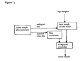
- Figure 1b shows the overall system including phase synthesis generator, input sample memory, and filtering to yield output samples.
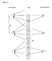
- Figure 1c shows image resampling: if the left image is the input and the right image is the output, then the resampling is a decimation of about 1.5 to 1; whereas, if the right image is the input and the left image is the output, then the resampling is a zoom by a factor of about 1.5. Note that the number of pixels changes, the image size changes, the number of pixels within the image changes, but the size/spacing of the pixels remains constant (and depends only on the display device).
- the preferred embodiment system thus has one or more of the following advantages: (1) control of interpixel scannings in resampling from field to field, field to frame, frame to field, and frame to frame formats (to adapt the incoming video nature to the output display device); (2) resampling phase synthesis with higher resolution than used for poly-phase filter selection to maintain phase accuracy among the picture; (3) adaptation (for simplified decimation) to bilinear filtering and hybrid equations; and (4) starting phase initialization for features such as horizontal and/or vertical panning.
- Preferred embodiment systems include preferred embodiment image resampling methods which may be invoked prior to or after other encoding or decoding, such as MPEG or JPEG (de)compressions, for video and still images.
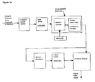
- Figures 1d-1e illustrate video display systems which include a preferred embodiment type resampler (resizer, rescaler).
- the system has a motion compensated video (e.g., MPEG) decoder; a rescaler of the foregoing type which provides resamplings in the range from zooms of 4 to 1 to decimations of 1 to 4; a discrete decimator with fixed-ratio resamplings of 1 to 1, 1 to 2, and 1 to 4; a second input for picture-in-picture or windows type image combinations using a second discrete decimator with fixed-ratio resamplings; a memory; and an OSD (on screen display) processor for the picture-in-picture (windows) display blending from the two inputs.
- the combination of the rescaler providing resamplings in the range 4:1 to 1:4 with the discrete decimator allows for overall resamplings in the range 4:1 to 1:16 for the first input.
- converters between YUV and RGB (or other) formats may be included.
- Plus display aspect ratio management (resizing) may be affiliated with the rescaling to provide adjustments between input and output formats such as 4x3, 16x9, and 20x9 formats.
- the display aspect ratio management may include horizontal cropping (pan & scan) and letter box (top and bottom non-image bars insertion) to make 16x9 input fit on a 4x3 monitor.
- the resampling computations can be performed with digital signal processors (DSPs) or general purpose or specialized programmable processors or application specific circuitry or systems on a chip with mutliple processors and functionalities such as a system with RISC controller processor plus a DSP and/or specialized processors/accelerators for computation intensive functions such as the filterings.
- DSPs digital signal processors
- a stored program in an onboard or external ROM, flash EEPROM, or ferroelectric RAM for a DSP or programmable processor could, in part, be dynamically loaded for configuration.
- Analog-to-digital converters and digital-to-analog converters provide coupling to the real world, and modulators and demodulators (plus antennas for air interfaces) provide coupling for transmission waveforms.
- the input image/video can be packetized and transmitted over networks such as the Internet.
- the system of Figure 1e illustrates a transport packet parser to separate out the video from other (e.g., audio) information
- Figure 1a illustrates a first preferred embodiment phase synthesis circuit which drives both memory fetches of input samples and filter coefficients to compute output samples as shown in Figure 1b.
- INC is the number of phase steps between successive output samples.
- INC may be larger than D (as for decimation) or smaller than D (as for zoom) or equal to D (as for a pan). Also, INC could vary within an image for special effects.
- S must be at least as large as the largest number of filter taps of the filterings and also must be at least as large as the maximum decimation rate.
- the accumulator overflow just matches the address overflow of the input buffer, and the highest log 2 S bits (e.g, 4 bits) from the accumulator directly address the starting point in the input buffer for the resampling filtering computations.
- the horizontal and vertical resamplings can be interleaved: after a horizontal resampling of samples within a line, one or more vertical line resamplings (for a zoom) may be performed. In this manner the resampled (resized) image can be displayed in raster scan order as it is being resampled. And for real-time operation the output samples are generated at an overall rate (1.78) 2 times the incoming input sample rate. Also, the vertical and horizontal resampling (resizing) factors may differ.
- the method includes horizontal resampling for each line (row) of pixels and vertical resampling of the lines, including interlaced or progressive frames, with the following steps (which omit description of action at accumulator overflow plus fetch samples for pipelined filtering):
- the third preferred embodiments uses optionally a simpler bilinear line filtering for decimations greater than 2 to 1 based on the fact that NewLine in the second preferred embodiment always equals at least 2, and a line is not used more than once in a bilinear interpolation .
- the bilinear filtering would be: Figure 5 compares a 4-tap filtering with bilinear filtering.
- Figure 3 illustrates a hybrid device operational in various modes.
- SINT simple interpolation
- the Figure 3 block diagram does not show how the lines should be read from memory nor show the filter itself.
- the IN_MODE is the input field/frame mode indication; OUT_MODE is the output field/frame mode indication; IN_POLAR TOP/BOTTOM field, only valid if IN_MODE is field; OUT_POLAR TOP/BOTTOM field, only valid if OUT_MODE is field; IN_OFFSET is the initial offset phase.
- the foregoing preferred embodiments can include filter response adaptation in the down-sampling modes to avoid aliasing.
- the filter response (which set of filter coefficients) derives from the INC (and D) value because INC represents the resampling ratio, both for a row of samples and for a set of lines.
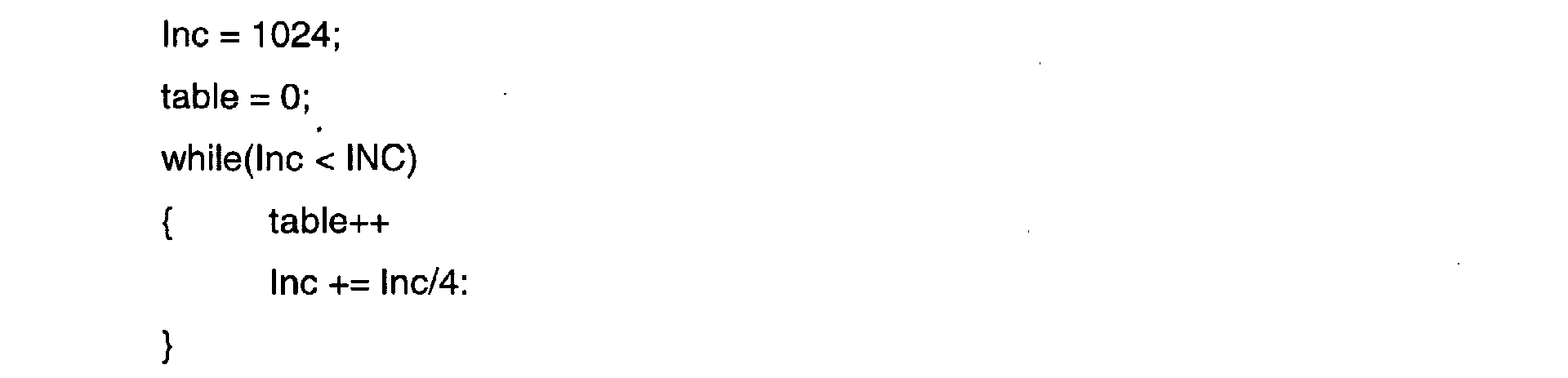
- logarithmic response by: where "table" is a number that indicates the appropriate response curve to be selected.
- the preferred embodiments may be modified in various ways while retaining one or more of the features of an output phase accumulator with bits split into three groups (input sample addressing, filter coefficient selection, and used only to maintain accuracy),
- the phase between input samples (D) can be taken larger or smaller than 1024, and may depend upon the resolution required; the number of phase bits used as the subpixel phase bits to select filter coefficients can be taken larger or smaller than D/2, for example D/4 or 3*D/4; the sets of filter coefficients could be for filters with more or less than the 2 and 4 taps used for illustration; the output phase could be used for resampling audio or other one-dimensional inputs or three-dimensional or higher arrays such as video sequence files, and so forth.
Landscapes
- Physics & Mathematics (AREA)
- General Physics & Mathematics (AREA)
- Engineering & Computer Science (AREA)
- Theoretical Computer Science (AREA)
- Television Systems (AREA)
- Editing Of Facsimile Originals (AREA)
- Image Processing (AREA)
- Studio Circuits (AREA)
Abstract
Description
- The present invention relates generally to digital image processing, and more particularly to image resampling methods and circuitry.
- Modern digital video systems typically require a resolution conversion capability for applications such as displaying HDTV signals at standard TV resolution, zooming, decimating, and providing picture-in-picture display. Poly-phase filtering allows accurate constant resampling ratios and may use predefined state machines to control pixel input pipelining and filter coefficient addressing according to predefined phase sequences. However, such filters are not flexible enough because they require adaptation each time a new conversion ratio is needed by a new application. Also, new video environment applications require new process capabilities such as frame rate conversions and play speed control. Those applications involve spatial field or frame interpolation capabilities that are usually offered with only a fixed number of predefined ratios, and this hinders vertical filtering.
- Adams et al, A Monolithic Asynchronous Sample-Rate Converter for Digital Audio, ISCAS '93, pp.1963-1966 (1993), disclose an integrated circuit providing audio sampling rate conversion with feedback tracking of the timing of output sample requests. This also shows experimental results for an input sampling rate of 48 KHz converted to an output sampling rate of 44.1 KHz.
- The present invention provides image and video resampling with an output phase accumulator driving input sample/line fetch plus filter coefficient selection.
- This has advantages including simple implementation of field/frame modes of line resampling, of image panning, and/or of adaptation of resampling filtering method to the resampling ratio.
- Various features and aspects of the present invention will hereafter be described in greater detail, by way of example only, and with reference to the preferred and illustrative embodiments shown in the accompanying drawings in which:
- Figures 1a-1e illustrate a first preferred embodiment resampling system and method of resampling;
- Figure 2 shows a second preferred embodiment;
- Figure 3 is a third preferred embodiment;
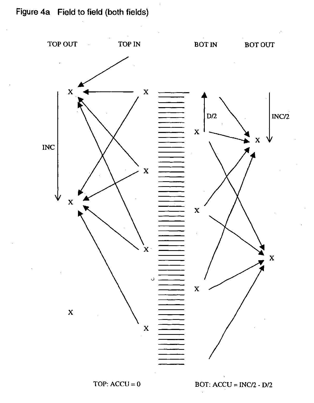
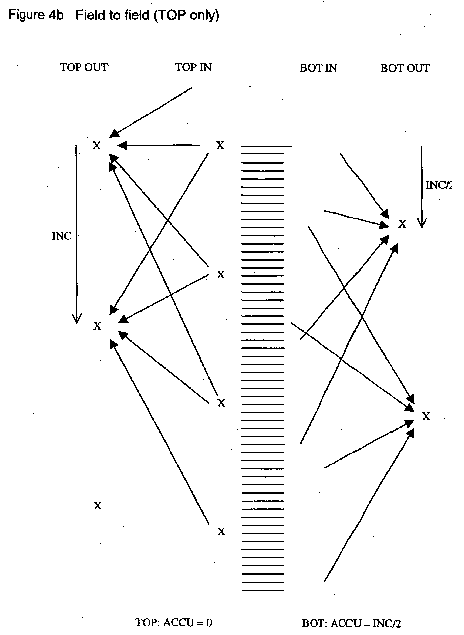
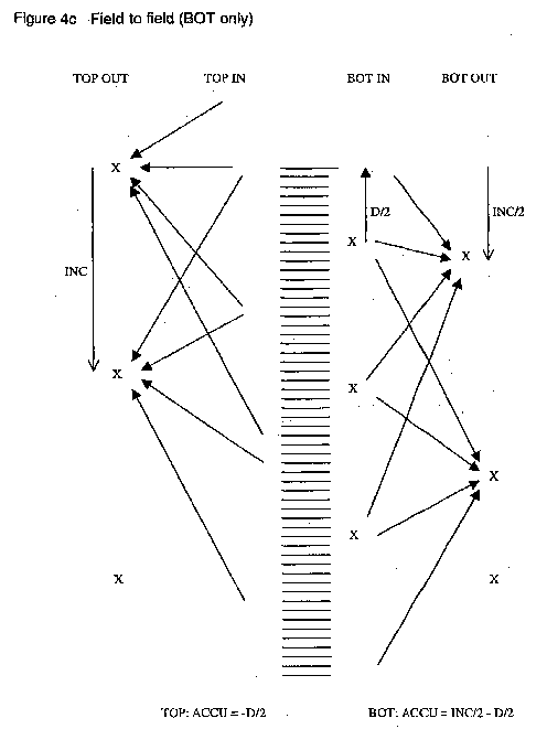
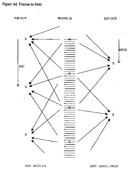
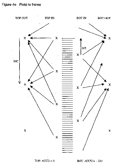
- Figures 4a-4e show preferred embodiment resampling categories; and
- Figure 5 compares bilinear and linear filterings.
-
- Preferred embodiment image/video resampling (resizing, rescaling) methods utilize a phase synthesis for output samples (pixel values) within a line plus phase synthesis for output lines (rows) which provides both input sample or line fetch control (integer part of the phase) plus poly-phase filter coefficient set selection (higher order bits of the fractional part of the phase). The resampling may select from different filtering approaches (linear, bilinear, etc.), and the phases are quantized to select corresponding poly-phase filters to simplify the filtering. Figure 1a illustrates a phase synthesis circuit which includes an initial offset capability for features such as panning and field/frame resampling. Figure 1b shows the overall system including phase synthesis generator, input sample memory, and filtering to yield output samples. Figure 1c shows image resampling: if the left image is the input and the right image is the output, then the resampling is a decimation of about 1.5 to 1; whereas, if the right image is the input and the left image is the output, then the resampling is a zoom by a factor of about 1.5. Note that the number of pixels changes, the image size changes, the number of pixels within the image changes, but the size/spacing of the pixels remains constant (and depends only on the display device).
- The preferred embodiment system thus has one or more of the following advantages: (1) control of interpixel scannings in resampling from field to field, field to frame, frame to field, and frame to frame formats (to adapt the incoming video nature to the output display device); (2) resampling phase synthesis with higher resolution than used for poly-phase filter selection to maintain phase accuracy among the picture; (3) adaptation (for simplified decimation) to bilinear filtering and hybrid equations; and (4) starting phase initialization for features such as horizontal and/or vertical panning.
- Preferred embodiment systems include preferred embodiment image resampling methods which may be invoked prior to or after other encoding or decoding, such as MPEG or JPEG (de)compressions, for video and still images.
- Figures 1d-1e illustrate video display systems which include a preferred embodiment type resampler (resizer, rescaler). In particular, the system has a motion compensated video (e.g., MPEG) decoder; a rescaler of the foregoing type which provides resamplings in the range from zooms of 4 to 1 to decimations of 1 to 4; a discrete decimator with fixed-ratio resamplings of 1 to 1, 1 to 2, and 1 to 4; a second input for picture-in-picture or windows type image combinations using a second discrete decimator with fixed-ratio resamplings; a memory; and an OSD (on screen display) processor for the picture-in-picture (windows) display blending from the two inputs. The combination of the rescaler providing resamplings in the range 4:1 to 1:4 with the discrete decimator allows for overall resamplings in the range 4:1 to 1:16 for the first input.
- Additionally, converters between YUV and RGB (or other) formats may be included. Plus display aspect ratio management (resizing) may be affiliated with the rescaling to provide adjustments between input and output formats such as 4x3, 16x9, and 20x9 formats. For example, the display aspect ratio management may include horizontal cropping (pan & scan) and letter box (top and bottom non-image bars insertion) to make 16x9 input fit on a 4x3 monitor.
- The resampling computations can be performed with digital signal processors (DSPs) or general purpose or specialized programmable processors or application specific circuitry or systems on a chip with mutliple processors and functionalities such as a system with RISC controller processor plus a DSP and/or specialized processors/accelerators for computation intensive functions such as the filterings. A stored program in an onboard or external ROM, flash EEPROM, or ferroelectric RAM for a DSP or programmable processor could, in part, be dynamically loaded for configuration. Analog-to-digital converters and digital-to-analog converters provide coupling to the real world, and modulators and demodulators (plus antennas for air interfaces) provide coupling for transmission waveforms. The input image/video can be packetized and transmitted over networks such as the Internet. The system of Figure 1e illustrates a transport packet parser to separate out the video from other (e.g., audio) information within packets.
- Figure 1a illustrates a first preferred embodiment phase synthesis circuit which drives both memory fetches of input samples and filter coefficients to compute output samples as shown in Figure 1b. For resampling an image or video stream, the system of Figures 1a-1b first resamples each row of pixels (line) and then resamples the set of lines. The system operates to resample a row of pixels as follows. First, subdivide the distance (phase) between successive input samples (pixel values) into D steps; D relates to the normalized distance between each sample and, for example, may be taken equal to 1024 (= 210). Next, for resampling a row of N pixels into a row of N' pixels, define an increment, INC, equal to (rounded off) D*N/N'; INC is the number of phase steps between successive output samples. INC may be larger than D (as for decimation) or smaller than D (as for zoom) or equal to D (as for a pan). Also, INC could vary within an image for special effects.
- Then compute the phase of the next output sample using the accumulator of Figure 1a; the accumulator width is log2D + log2S bits (e.g., 14 bits) where S is the size of the circular input sample buffer and is taken to be a power of 2 (e.g., 24 =16). Of course, S must be at least as large as the largest number of filter taps of the filterings and also must be at least as large as the maximum decimation rate. With this size accumulator, the accumulator overflow just matches the address overflow of the input buffer, and the highest log2S bits (e.g, 4 bits) from the accumulator directly address the starting point in the input buffer for the resampling filtering computations. And a few bits (e.g., 5 bits) of the most significant of the lowest log2D bits (e.g., 10 bits) of the accumulator select the set of filter coefficients. This use of only a subset of the lower accumulator bits limits the number of sets of filter coefficients that must be stored without a significant degradation in quality.
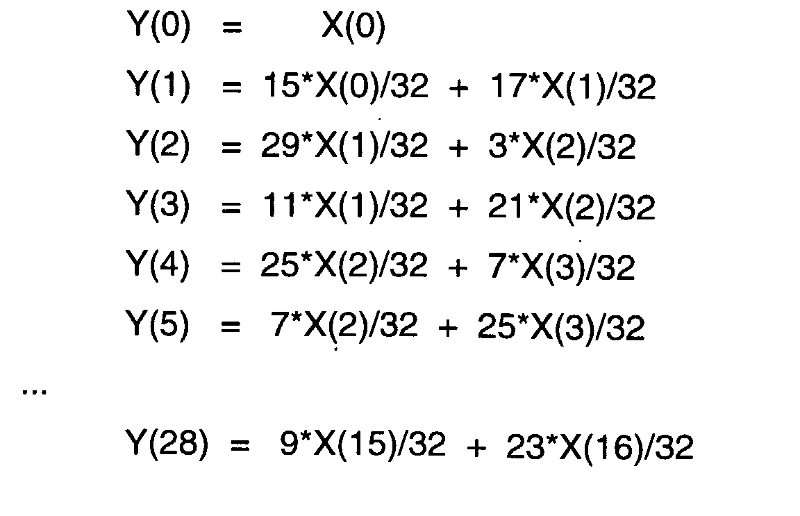
- More explicitly, consider examples of an image zoom and an image decimation. As a zoom example, presume the input line of samples X(0), X(1), ..., X(99) is to be zoomed by a factor of 1.78 to yield the output line of samples Y(0), Y(1), ..., Y(177). (Filter width at the image boundary frequently requires some padding to define samples such as X(-1) and X(100).) Take the circular input sample buffer size S = 16, the input sample distance D = 1024, and 5-bit filter coefficient selection. This D yields INC = 575, and the Figure 1a circuit has a 14-bit accumulator which generates the Y() phases (expressed as 1024*multipixel + 32*subpixel-phase + least significant):
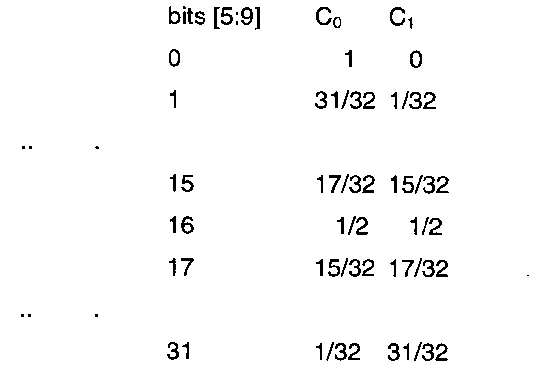
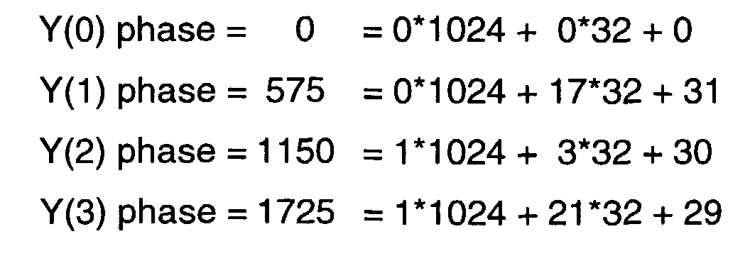 Thus accumulator least significant bits [0:4] are not used for addressing but are needed to maintain accumulator accuracy, subpixel phase bits [5:9] select the set of filter coefficients, and multipixel bits [10:13] address the circular input sample buffer. As a simple filter example, consider a bilinear filter with coefficients C0 for X(n) and C1 for X(n+1) where X(n) is the sample addressed by accumulator bits [10:13]. Thus Y(n) = C0*X(n) + C1*X(n+1) with the following sets of filter coefficients:
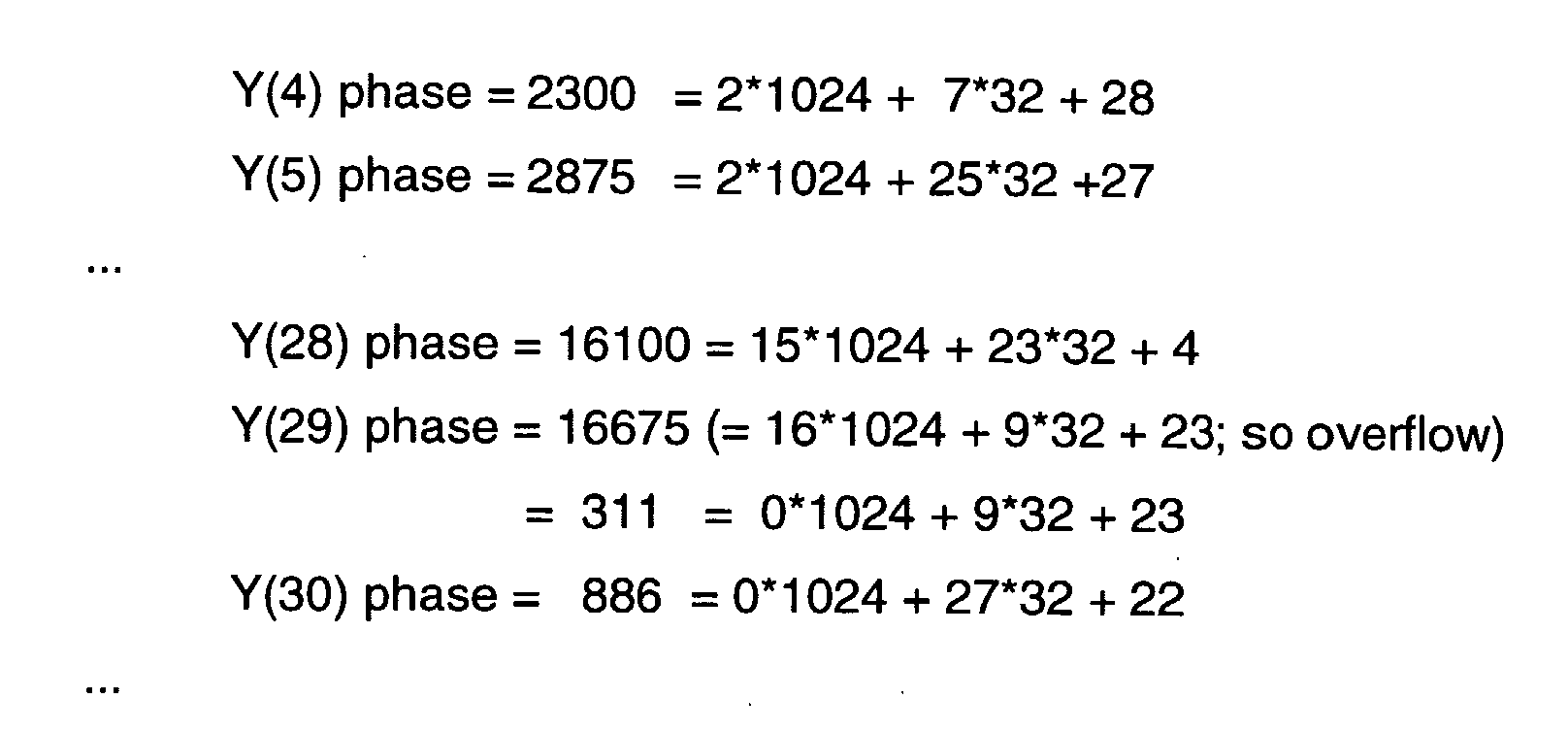
 Hence,

- And after the foregoing horizontal resamplings within the lines, vertically resample the lines in the same manner with X() representing the input lines and Y() the output lines. That is, an output line Y() has samples which are vertical filterings of corresponding samples of the input lines X(). Thus if the original image had 100 lines with each line containing 100 samples, first the foregoing horizontal resampling of the lines would generate 100 input lines for vertical resampling with each resampled line containing 178 samples; then the vertical resampling would generate 178 lines with each output line still containing 178 samples. Compute the 178 samples per output line as 178 vertical filterings using the corresponding samples of the 100 input 178-sample lines.
- Further, the horizontal and vertical resamplings can be interleaved: after a horizontal resampling of samples within a line, one or more vertical line resamplings (for a zoom) may be performed. In this manner the resampled (resized) image can be displayed in raster scan order as it is being resampled. And for real-time operation the output samples are generated at an overall rate (1.78)2 times the incoming input sample rate. Also, the vertical and horizontal resampling (resizing) factors may differ.
- Similarly for a simple decimation example presume input samples X(0), X(1), ... X(299) are to be decimated by a factor of 3 to yield the output samples Y(0), Y(1), ... Y(99). Again taking S = 16 and D = 1024 yields INC = 3072, so the Figure 1a circuit generates the Y() phases:For this integer decimation the same filter coefficients are used for all filterings because the accumulator bits [5:9] remain constant (all 0's). With an initial offset, the bits [5:9] will still remain constant, although not necessarily all 0's, and the filter coefficients again remain the same for all filterings.

- Again, after resampling within each line, resample the set of lines.
- Figure 2 illustrates second preferred embodiment image resampling system and method which is analogous to that illustrated in Figures 1a-1b; indeed, Figure 2 implements the case of D = 1024 and 32 poly-phase filters together with the accumulator of Figure 1a as a register (REG) plus adder. The method includes horizontal resampling for each line (row) of pixels and vertical resampling of the lines, including interlaced or progressive frames, with the following steps (which omit description of action at accumulator overflow plus fetch samples for pipelined filtering):
- (a) select an input pixel distance normalization, D, such as 1024, which typically will be on the order of horizontal or vertical size of the image and represent the number of phase steps between input samples (pixel values).
- (b) select an output increment, INC, to be approximately D times the resampling
ratio, so INC will be the number of phase steps between output pixels:
- (c) select an initial offset in terms of phase steps (fraction of a pixel difference
offset multiplied by D) and initialize the register with this value:
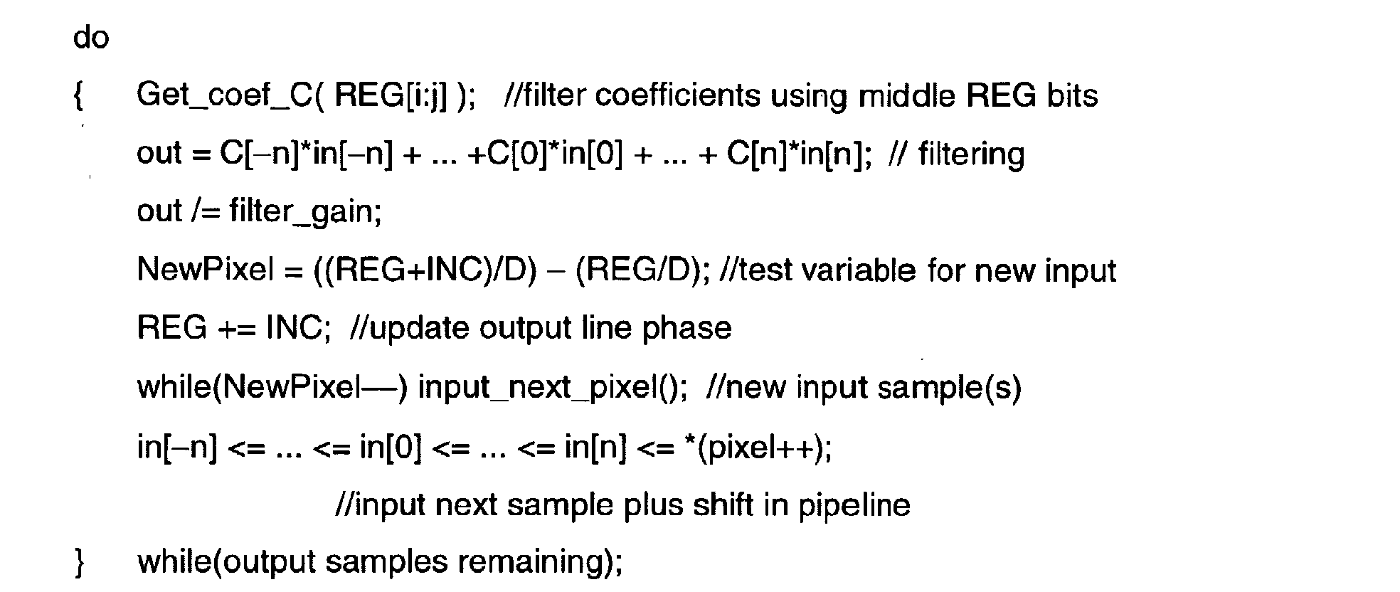
- (d) generate the output samples in a line (row of pixels) with the following filtering
loop, the input samples are pipelined with in[k] the kth entry in the pipeline. Note the
center tap of the filter is C[0], and the output phase multipixel part fetched the in[0]
sample in the pipeline.
Thus the output sample phase (REG) is partitioned into three sets of bits: (1) the integer part of REG/D (and integer part of (REG + INC)/D) used to determine whether new input samples are needed, (2) the upper bits of the fractional part of REG/D, denoted REG[i:j] used to select the filter coefficients, and (3) the lower bits of the fractional part of REG/D which only accumulate.
- (e) select the scanning and interpolation mode for line resampling (vertical resampling). Both Video and Display device may be either in field scanned mode (interlaced) or frame scanned mode (progressive). Field scanned is the typical display in video; each field is scanned individually and sequentially to preserve the temporal coherency of the signal. The vertical resampling filtering can be considered to fall into one of four categories of scanning:
- (i) field input scanning TO field output scanning; (usual interlaced video with usual monitor device).
- (ii) field input scanning TO frame output scanning; (usual interlaced video with progressive display device such as LCD...).
- (iii) frame input scanning TO field output scanning; (usual progressive video such as movies with usual monitor device).
- (iv) frame input scanning TO frame output scanning; usual progressive video
such as movies with progressive display device such as LCD...).
The second preferred embodiment then applies filtering according to the
resampling RANGE, for example, with a range from zoom by 8 to decimation by 8. Full
band pass filter may be used for ANY zooming ratio while filter adaptation is required
depending on the decimation ratio. Optionally the device allows bilinear interpolation
which uses only two nearest lines because this simplification (i.e., only 2 filter taps)
provides acceptable quality without impacting the video burst bandwidth, for high
decimation ratios (for example above decimation 2:1). In fact, using the bilinear
interpolation method allows any ratio of vertical decimation at constant bandwidth.Because fields may be either TOP or BOTTOM (consisting of even numbered
lines/rows of pixels or odd numbered lines/rows of pixels, respectively) which differ in a
sense of relative vertical positioning from each other, the preferred embodiment
specifies accumulator preset (initial offset) rules as follows:
- 1. input = frame, output = frame, initial offset = 0
- 2. input = TOP, output = frame, initial offset = 0
- 3. input = BOTTOM, output = frame, initial offset = -D/2
- 4. input = frame, output = TOP, initial offset = 0
- 5. input = frame, output = BOTTOM, initial offset = INC/2
- 6. input = TOP, output = TOP, initial offset = 0
- 7. input = BOTTOM, output = TOP, initial offset = -D/2
- 8. input = TOP, output = BOTTOM, initial offset = INC/2
- 9. input = BOTTOM, output = BOTTOM, initial offset = INC/2 - D/2
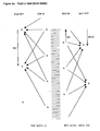
These offset categories are heuristically illustrated in Figures 4a-4e with the vertical direction corresponding to phase. - (f) resample lines again using phase generation by INC; the lines are pipelined
with L[k] indicating the kth pipeline entry. The pipeline index is centered at 0 which
corresponds to the filter center tap. Of course, the filtering of lines is, in fact, filtering
The input_next_line() function inputs a new line in the input pipeline while shifting all of the other lines already in the pipeline:
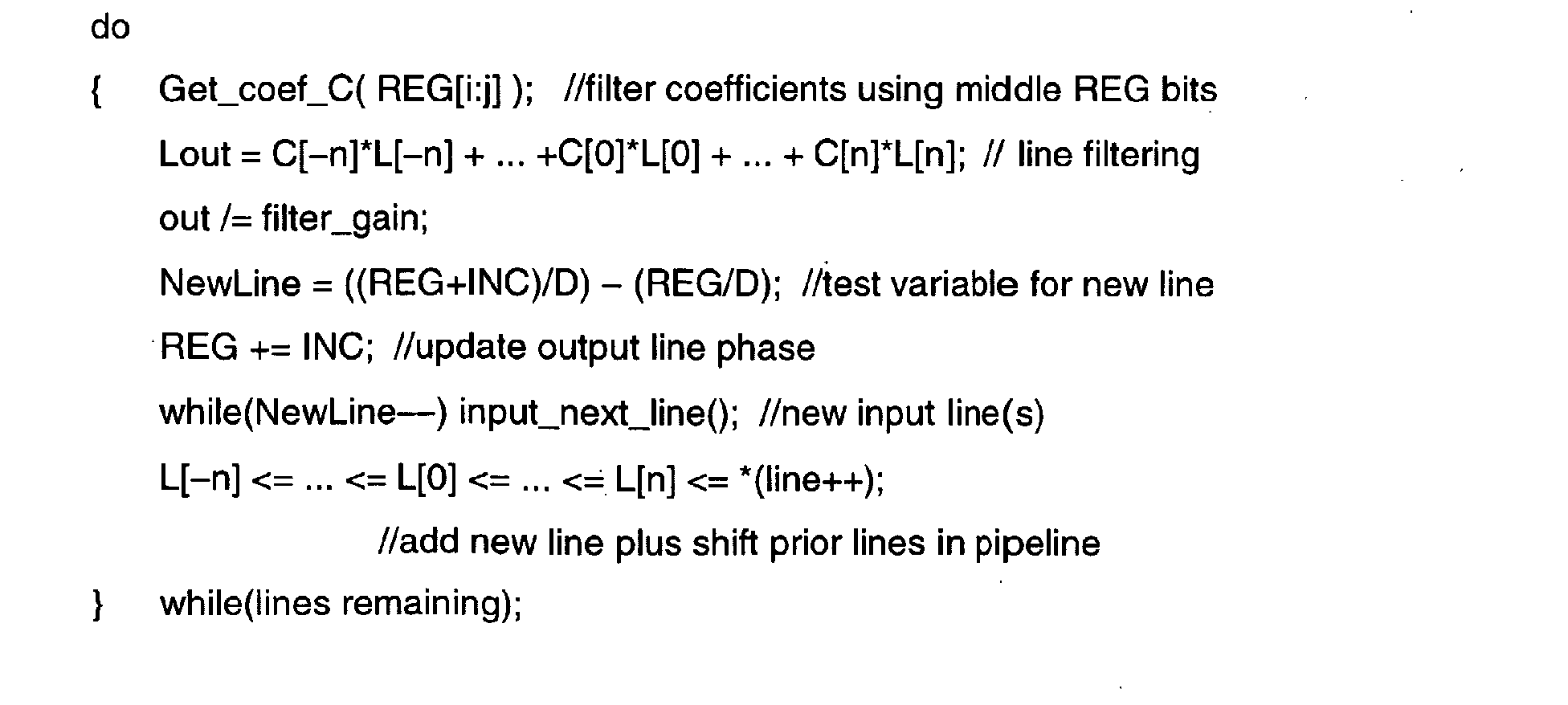
 where next_Line() inputs the next incoming line.
-
- The third preferred embodiments uses optionally a simpler bilinear line filtering for decimations greater than 2 to 1 based on the fact that NewLine in the second preferred embodiment always equals at least 2, and a line is not used more than once in a bilinear interpolation . In particular, the bilinear filtering would be:Figure 5 compares a 4-tap filtering with bilinear filtering.

- Figure 3 illustrates a hybrid device operational in various modes. In particular, define a variable SINT (simple interpolation) to apply bilinear interpolation for decimations with resampling ratio greater than 2 to 1:


- The Figure 3 block diagram does not show how the lines should be read from memory nor show the filter itself. The IN_MODE is the input field/frame mode indication; OUT_MODE is the output field/frame mode indication; IN_POLAR TOP/BOTTOM field, only valid if IN_MODE is field; OUT_POLAR TOP/BOTTOM field, only valid if OUT_MODE is field; IN_OFFSET is the initial offset phase.
- The foregoing preferred embodiments can include filter response adaptation in the down-sampling modes to avoid aliasing. In particular, the filter response (which set of filter coefficients) derives from the INC (and D) value because INC represents the resampling ratio, both for a row of samples and for a set of lines. Thus, for example, logarithmic response by:where "table" is a number that indicates the appropriate response curve to be selected.
- The preferred embodiments may be modified in various ways while retaining one or more of the features of an output phase accumulator with bits split into three groups (input sample addressing, filter coefficient selection, and used only to maintain accuracy),
- For example, the phase between input samples (D) can be taken larger or smaller than 1024, and may depend upon the resolution required; the number of phase bits used as the subpixel phase bits to select filter coefficients can be taken larger or smaller than D/2, for example D/4 or 3*D/4; the sets of filter coefficients could be for filters with more or less than the 2 and 4 taps used for illustration; the output phase could be used for resampling audio or other one-dimensional inputs or three-dimensional or higher arrays such as video sequence files, and so forth.
Claims (4)
- A method of sampling rate conversion using poly-phase filtering, the method comprising:(a) generating a phase with a first resolution; and(b) selecting poly-phase filters using said phase at a second resolution which is coarser than said first resolution.
- A method of image resampling using horizontal and vertical poly-phase filtering, the method comprising:(a) generating a phase using input parameters;(b) selecting poly-phase filters from said phase for horizontal filtering to output resampled lines, and(c) selecting poly-phase filters from said phase for vertical filtering of the resampled lines from step (b) to output a resampled image.
- The method of claim 2 wherein:(a) the image is in a video sequence with interlaced fields or progressive frames and(b) the vertical resampling adjusts among top field, bottom field, and frame by initial phase offsets.
- An image resampler, comprising:(a) a phase generator;(b) a filter coefficient memory with address input coupled to a quantized output of said phase generator; and(c) a filter with an image input and filter coefficients stored in said memory.
Priority Applications (4)
| Application Number | Priority Date | Filing Date | Title |
|---|---|---|---|
| AT01402611T ATE452385T1 (en) | 2001-10-10 | 2001-10-10 | DEVICE AND METHOD FOR IMAGE SCALING |
| EP01402611A EP1304650B1 (en) | 2001-10-10 | 2001-10-10 | Image scaling system and method |
| DE60140805T DE60140805D1 (en) | 2001-10-10 | 2001-10-10 | Device and method for image scaling |
| US10/268,391 US7119845B2 (en) | 2001-10-10 | 2002-10-10 | Image resizing system and method |
Applications Claiming Priority (1)
| Application Number | Priority Date | Filing Date | Title |
|---|---|---|---|
| EP01402611A EP1304650B1 (en) | 2001-10-10 | 2001-10-10 | Image scaling system and method |
Publications (2)
| Publication Number | Publication Date |
|---|---|
| EP1304650A1 true EP1304650A1 (en) | 2003-04-23 |
| EP1304650B1 EP1304650B1 (en) | 2009-12-16 |
Family
ID=8182918
Family Applications (1)
| Application Number | Title | Priority Date | Filing Date |
|---|---|---|---|
| EP01402611A Expired - Lifetime EP1304650B1 (en) | 2001-10-10 | 2001-10-10 | Image scaling system and method |
Country Status (4)
| Country | Link |
|---|---|
| US (1) | US7119845B2 (en) |
| EP (1) | EP1304650B1 (en) |
| AT (1) | ATE452385T1 (en) |
| DE (1) | DE60140805D1 (en) |
Cited By (3)
| Publication number | Priority date | Publication date | Assignee | Title |
|---|---|---|---|---|
| CN1293514C (en) * | 2004-07-08 | 2007-01-03 | 北京中星微电子有限公司 | Pantograph treatment system of digital picture |
| EP1816600A3 (en) * | 2006-02-06 | 2008-08-20 | Olympus Corporation | Image resolution conversion apparatus |
| EP2631869A1 (en) * | 2012-02-24 | 2013-08-28 | Apple Inc. | Parallel scaler processing |
Families Citing this family (11)
| Publication number | Priority date | Publication date | Assignee | Title |
|---|---|---|---|---|
| US7333141B2 (en) * | 2002-10-22 | 2008-02-19 | Texas Instruments Incorporated | Resampling methods for digital images |
| US8417066B2 (en) * | 2004-03-04 | 2013-04-09 | Broadcom Corporation | Method and system for polyphase filtering by combining IIR and FIR filters and its applications in video scaling |
| US8127242B1 (en) * | 2010-08-12 | 2012-02-28 | The United States Of America As Represented By The Secretary Of The Army | Graphic user interface and software for processing large size signal data samples in a small buffer using automatically adjusted decimation ratio |
| US7777812B2 (en) * | 2005-11-18 | 2010-08-17 | Sharp Laboratories Of America, Inc. | Methods and systems for picture resampling |
| TWI359614B (en) * | 2006-06-20 | 2012-03-01 | Via Tech Inc | Pip processing apparatus and processing method the |
| US20080012868A1 (en) * | 2006-07-14 | 2008-01-17 | Mediatek Inc. | Multimedia Playback System, Multimedia Data Reproduction Apparatus, and Method Thereof |
| US20090161016A1 (en) * | 2007-12-21 | 2009-06-25 | Wong Daniel W | Run-Time Selection Of Video Algorithms |
| KR20130052372A (en) * | 2011-11-11 | 2013-05-22 | 삼성전자주식회사 | Digital photographing apparatus and method thereof |
| US10755380B2 (en) | 2015-11-11 | 2020-08-25 | Texas Instruments Incorporated | Down scaling images in a computer vision system |
| US12327296B2 (en) * | 2021-07-21 | 2025-06-10 | Black Sesame Technologies Inc. | Cache-based warp engine |
| CN119547433A (en) * | 2022-06-28 | 2025-02-28 | 抖音视界有限公司 | Padding method for adaptive loop filter in video coding codec |
Citations (1)
| Publication number | Priority date | Publication date | Assignee | Title |
|---|---|---|---|---|
| GB2255469A (en) * | 1991-04-12 | 1992-11-04 | Abekas Video Systems | Digital sample rate converter. |
Family Cites Families (6)
| Publication number | Priority date | Publication date | Assignee | Title |
|---|---|---|---|---|
| US5274372A (en) * | 1992-10-23 | 1993-12-28 | Tektronix, Inc. | Sampling rate conversion using polyphase filters with interpolation |
| US5963261A (en) * | 1996-04-29 | 1999-10-05 | Philips Electronics North America Corporation | Low cost scan converter for television receiver |
| JP4345937B2 (en) * | 1998-11-10 | 2009-10-14 | キヤノン株式会社 | Image enlargement processing circuit |
| US6724826B1 (en) * | 2000-02-25 | 2004-04-20 | Ampex Corporation | Method and apparatus for improving the image quality of transmitted video signals via pre-filtering |
| US6765622B2 (en) * | 2001-10-26 | 2004-07-20 | Koninklijke Philips Electronics N.V. | Line-buffer reuse in vertical pixel-processing arrangement |
| US6894725B2 (en) * | 2001-12-03 | 2005-05-17 | Thomson Licensing S.A. | Sample rate converter system |
-
2001
- 2001-10-10 DE DE60140805T patent/DE60140805D1/en not_active Expired - Lifetime
- 2001-10-10 EP EP01402611A patent/EP1304650B1/en not_active Expired - Lifetime
- 2001-10-10 AT AT01402611T patent/ATE452385T1/en not_active IP Right Cessation
-
2002
- 2002-10-10 US US10/268,391 patent/US7119845B2/en not_active Expired - Lifetime
Patent Citations (1)
| Publication number | Priority date | Publication date | Assignee | Title |
|---|---|---|---|---|
| GB2255469A (en) * | 1991-04-12 | 1992-11-04 | Abekas Video Systems | Digital sample rate converter. |
Non-Patent Citations (2)
| Title |
|---|
| ADAMS R W ET AL: "A MONOLITHIC ASYNCHRONOUS SAMPLE-RATE CONVERTER FOR DIGITAL AUDIO", PROCEEDINGS OF THE INTERNATIONAL SYMPOSIUM ON CIRCUITS AND SYSTEMS. (ISCS). CHICAGO, MAY 3 - 6, 1993, NEW YORK, IEEE, US, vol. 3, 3 May 1993 (1993-05-03), pages 1963 - 1966, XP000390078, ISBN: 0-7803-1281-3 * |
| NIE X ET AL: "A NEW VLSI ARCHITECTURE FOR INTERLEAVED FILTERING OF SAMPLED SIGNALS", IEEE TRANSACTIONS ON CONSUMER ELECTRONICS, IEEE INC. NEW YORK, US, vol. 44, no. 3, August 1998 (1998-08-01), pages 926 - 929, XP000851601, ISSN: 0098-3063 * |
Cited By (4)
| Publication number | Priority date | Publication date | Assignee | Title |
|---|---|---|---|---|
| CN1293514C (en) * | 2004-07-08 | 2007-01-03 | 北京中星微电子有限公司 | Pantograph treatment system of digital picture |
| EP1816600A3 (en) * | 2006-02-06 | 2008-08-20 | Olympus Corporation | Image resolution conversion apparatus |
| US7567733B2 (en) | 2006-02-06 | 2009-07-28 | Olympus Corporation | Image resolution conversion apparatus |
| EP2631869A1 (en) * | 2012-02-24 | 2013-08-28 | Apple Inc. | Parallel scaler processing |
Also Published As
| Publication number | Publication date |
|---|---|
| US20030122960A1 (en) | 2003-07-03 |
| ATE452385T1 (en) | 2010-01-15 |
| EP1304650B1 (en) | 2009-12-16 |
| DE60140805D1 (en) | 2010-01-28 |
| US7119845B2 (en) | 2006-10-10 |
Similar Documents
| Publication | Publication Date | Title |
|---|---|---|
| US6239847B1 (en) | Two pass multi-dimensional data scaling arrangement and method thereof | |
| EP1739959B1 (en) | Image pickup apparatus and method | |
| EP0579795B1 (en) | Digital image interpolation system for zoom and pan effects | |
| EP1304650B1 (en) | Image scaling system and method | |
| AU615701B2 (en) | High definition video signal processing | |
| US7477323B2 (en) | Method and system for digital image magnification and reduction | |
| JPH11509071A (en) | Composite format scan conversion | |
| EP2293237B1 (en) | Image processing method | |
| US5666160A (en) | Digital zooming system of high resolution and method therefor | |
| US6388711B1 (en) | Apparatus for converting format for digital television | |
| US6542201B1 (en) | Zooming apparatus and method in digital TV | |
| JPH08275122A (en) | Video format converter and conversion method | |
| US20010055066A1 (en) | Imaging apparatus | |
| EP0629044B1 (en) | Digital signal processing | |
| US7142236B2 (en) | Digital zoom apparatus to perform zoom during successive changes in zoom magnification | |
| US6917383B2 (en) | Image sensing device | |
| US5668602A (en) | Real-time television image pixel multiplication methods and apparatus | |
| KR100719988B1 (en) | Image signal processing device | |
| US6501508B1 (en) | Video format converter for digital receiving system | |
| US7421150B2 (en) | Coordinate conversion apparatus and method | |
| EP0497428B1 (en) | Interphone with television | |
| KR100311009B1 (en) | Apparatus and method for converting video format using common format | |
| EP0589721A1 (en) | Digital zooming circuit with compensation of the edge degradation | |
| US20100066901A1 (en) | Apparatus and method for processing video data | |
| EP0802671B1 (en) | Digital signal processing circuit for a television receiver |
Legal Events
| Date | Code | Title | Description |
|---|---|---|---|
| PUAI | Public reference made under article 153(3) epc to a published international application that has entered the european phase |
Free format text: ORIGINAL CODE: 0009012 |
|
| 17P | Request for examination filed |
Effective date: 20011010 |
|
| AK | Designated contracting states |
Designated state(s): AT BE CH CY DE DK ES FI FR GB GR IE IT LI LU MC NL PT SE TR |
|
| AX | Request for extension of the european patent |
Extension state: AL LT LV MK RO SI |
|
| AKX | Designation fees paid |
Designated state(s): AT BE CH CY DE DK ES FI FR GB GR IE IT LI LU MC NL PT SE TR |
|
| GRAP | Despatch of communication of intention to grant a patent |
Free format text: ORIGINAL CODE: EPIDOSNIGR1 |
|
| GRAS | Grant fee paid |
Free format text: ORIGINAL CODE: EPIDOSNIGR3 |
|
| GRAA | (expected) grant |
Free format text: ORIGINAL CODE: 0009210 |
|
| AK | Designated contracting states |
Kind code of ref document: B1 Designated state(s): AT BE CH CY DE DK ES FI FR GB GR IE IT LI LU MC NL PT SE TR |
|
| REG | Reference to a national code |
Ref country code: GB Ref legal event code: FG4D |
|
| REG | Reference to a national code |
Ref country code: CH Ref legal event code: EP |
|
| REG | Reference to a national code |
Ref country code: IE Ref legal event code: FG4D |
|
| REF | Corresponds to: |
Ref document number: 60140805 Country of ref document: DE Date of ref document: 20100128 Kind code of ref document: P |
|
| REG | Reference to a national code |
Ref country code: NL Ref legal event code: VDEP Effective date: 20091216 |
|
| PG25 | Lapsed in a contracting state [announced via postgrant information from national office to epo] |
Ref country code: SE Free format text: LAPSE BECAUSE OF FAILURE TO SUBMIT A TRANSLATION OF THE DESCRIPTION OR TO PAY THE FEE WITHIN THE PRESCRIBED TIME-LIMIT Effective date: 20091216 Ref country code: FI Free format text: LAPSE BECAUSE OF FAILURE TO SUBMIT A TRANSLATION OF THE DESCRIPTION OR TO PAY THE FEE WITHIN THE PRESCRIBED TIME-LIMIT Effective date: 20091216 |
|
| PG25 | Lapsed in a contracting state [announced via postgrant information from national office to epo] |
Ref country code: AT Free format text: LAPSE BECAUSE OF FAILURE TO SUBMIT A TRANSLATION OF THE DESCRIPTION OR TO PAY THE FEE WITHIN THE PRESCRIBED TIME-LIMIT Effective date: 20091216 |
|
| PG25 | Lapsed in a contracting state [announced via postgrant information from national office to epo] |
Ref country code: PT Free format text: LAPSE BECAUSE OF FAILURE TO SUBMIT A TRANSLATION OF THE DESCRIPTION OR TO PAY THE FEE WITHIN THE PRESCRIBED TIME-LIMIT Effective date: 20100416 Ref country code: NL Free format text: LAPSE BECAUSE OF FAILURE TO SUBMIT A TRANSLATION OF THE DESCRIPTION OR TO PAY THE FEE WITHIN THE PRESCRIBED TIME-LIMIT Effective date: 20091216 Ref country code: ES Free format text: LAPSE BECAUSE OF FAILURE TO SUBMIT A TRANSLATION OF THE DESCRIPTION OR TO PAY THE FEE WITHIN THE PRESCRIBED TIME-LIMIT Effective date: 20100327 |
|
| PG25 | Lapsed in a contracting state [announced via postgrant information from national office to epo] |
Ref country code: BE Free format text: LAPSE BECAUSE OF FAILURE TO SUBMIT A TRANSLATION OF THE DESCRIPTION OR TO PAY THE FEE WITHIN THE PRESCRIBED TIME-LIMIT Effective date: 20091216 |
|
| PLBE | No opposition filed within time limit |
Free format text: ORIGINAL CODE: 0009261 |
|
| STAA | Information on the status of an ep patent application or granted ep patent |
Free format text: STATUS: NO OPPOSITION FILED WITHIN TIME LIMIT |
|
| PG25 | Lapsed in a contracting state [announced via postgrant information from national office to epo] |
Ref country code: CY Free format text: LAPSE BECAUSE OF FAILURE TO SUBMIT A TRANSLATION OF THE DESCRIPTION OR TO PAY THE FEE WITHIN THE PRESCRIBED TIME-LIMIT Effective date: 20091216 Ref country code: GR Free format text: LAPSE BECAUSE OF FAILURE TO SUBMIT A TRANSLATION OF THE DESCRIPTION OR TO PAY THE FEE WITHIN THE PRESCRIBED TIME-LIMIT Effective date: 20100317 |
|
| 26N | No opposition filed |
Effective date: 20100917 |
|
| PG25 | Lapsed in a contracting state [announced via postgrant information from national office to epo] |
Ref country code: DK Free format text: LAPSE BECAUSE OF FAILURE TO SUBMIT A TRANSLATION OF THE DESCRIPTION OR TO PAY THE FEE WITHIN THE PRESCRIBED TIME-LIMIT Effective date: 20091216 |
|
| PG25 | Lapsed in a contracting state [announced via postgrant information from national office to epo] |
Ref country code: IT Free format text: LAPSE BECAUSE OF FAILURE TO SUBMIT A TRANSLATION OF THE DESCRIPTION OR TO PAY THE FEE WITHIN THE PRESCRIBED TIME-LIMIT Effective date: 20091216 |
|
| PG25 | Lapsed in a contracting state [announced via postgrant information from national office to epo] |
Ref country code: MC Free format text: LAPSE BECAUSE OF NON-PAYMENT OF DUE FEES Effective date: 20101031 |
|
| REG | Reference to a national code |
Ref country code: CH Ref legal event code: PL |
|
| PG25 | Lapsed in a contracting state [announced via postgrant information from national office to epo] |
Ref country code: CH Free format text: LAPSE BECAUSE OF NON-PAYMENT OF DUE FEES Effective date: 20101031 Ref country code: LI Free format text: LAPSE BECAUSE OF NON-PAYMENT OF DUE FEES Effective date: 20101031 |
|
| PG25 | Lapsed in a contracting state [announced via postgrant information from national office to epo] |
Ref country code: IE Free format text: LAPSE BECAUSE OF NON-PAYMENT OF DUE FEES Effective date: 20101010 |
|
| PG25 | Lapsed in a contracting state [announced via postgrant information from national office to epo] |
Ref country code: LU Free format text: LAPSE BECAUSE OF NON-PAYMENT OF DUE FEES Effective date: 20101010 |
|
| PG25 | Lapsed in a contracting state [announced via postgrant information from national office to epo] |
Ref country code: TR Free format text: LAPSE BECAUSE OF FAILURE TO SUBMIT A TRANSLATION OF THE DESCRIPTION OR TO PAY THE FEE WITHIN THE PRESCRIBED TIME-LIMIT Effective date: 20091216 |
|
| REG | Reference to a national code |
Ref country code: FR Ref legal event code: PLFP Year of fee payment: 16 |
|
| REG | Reference to a national code |
Ref country code: FR Ref legal event code: PLFP Year of fee payment: 17 |
|
| PGFP | Annual fee paid to national office [announced via postgrant information from national office to epo] |
Ref country code: GB Payment date: 20170925 Year of fee payment: 17 Ref country code: FR Payment date: 20170922 Year of fee payment: 17 |
|
| PGFP | Annual fee paid to national office [announced via postgrant information from national office to epo] |
Ref country code: DE Payment date: 20171027 Year of fee payment: 17 |
|
| REG | Reference to a national code |
Ref country code: DE Ref legal event code: R119 Ref document number: 60140805 Country of ref document: DE |
|
| GBPC | Gb: european patent ceased through non-payment of renewal fee |
Effective date: 20181010 |
|
| PG25 | Lapsed in a contracting state [announced via postgrant information from national office to epo] |
Ref country code: DE Free format text: LAPSE BECAUSE OF NON-PAYMENT OF DUE FEES Effective date: 20190501 |
|
| PG25 | Lapsed in a contracting state [announced via postgrant information from national office to epo] |
Ref country code: FR Free format text: LAPSE BECAUSE OF NON-PAYMENT OF DUE FEES Effective date: 20181031 |
|
| PG25 | Lapsed in a contracting state [announced via postgrant information from national office to epo] |
Ref country code: GB Free format text: LAPSE BECAUSE OF NON-PAYMENT OF DUE FEES Effective date: 20181010 |