EP1304600A2 - Systems and methods for liquid immersion development - Google Patents
Systems and methods for liquid immersion development Download PDFInfo
- Publication number
- EP1304600A2 EP1304600A2 EP02023408A EP02023408A EP1304600A2 EP 1304600 A2 EP1304600 A2 EP 1304600A2 EP 02023408 A EP02023408 A EP 02023408A EP 02023408 A EP02023408 A EP 02023408A EP 1304600 A2 EP1304600 A2 EP 1304600A2
- Authority
- EP
- European Patent Office
- Prior art keywords
- toner
- image
- station
- substrate
- solution
- Prior art date
- Legal status (The legal status is an assumption and is not a legal conclusion. Google has not performed a legal analysis and makes no representation as to the accuracy of the status listed.)
- Granted
Links
Images



Classifications
-
- G—PHYSICS
- G03—PHOTOGRAPHY; CINEMATOGRAPHY; ANALOGOUS TECHNIQUES USING WAVES OTHER THAN OPTICAL WAVES; ELECTROGRAPHY; HOLOGRAPHY
- G03G—ELECTROGRAPHY; ELECTROPHOTOGRAPHY; MAGNETOGRAPHY
- G03G15/00—Apparatus for electrographic processes using a charge pattern
- G03G15/06—Apparatus for electrographic processes using a charge pattern for developing
- G03G15/10—Apparatus for electrographic processes using a charge pattern for developing using a liquid developer
- G03G15/104—Preparing, mixing, transporting or dispensing developer
- G03G15/105—Detection or control means for the toner concentration
Definitions
- the present invention relates generally to electrophotographic printing in image forming systems, and specifically relates to liquid immersion development of color prints.
- Electrophotographic systems employing liquid immersion development (LID) technologies are well known. These types of systems typically include an image bearing member or photoreceptor having an image bearing surface on which latent images are formed and developed as single color or multiple color toner images for eventual transfer to a receiver substrate or copy sheet. Such electrophotographic systems also include a development station that utilizes a liquid developer material typically having about 2 percent by weight of charged, solid particulate toner material of a particular color, that is dispersed at a desired concentration in a clear liquid carrier.
- a liquid developer material typically having about 2 percent by weight of charged, solid particulate toner material of a particular color, that is dispersed at a desired concentration in a clear liquid carrier.
- the latent images formed on the image bearing surface of the image bearing member or photoreceptor are developed with the charged toner particles, with excess liquid carrier being left behind or removed such that the developed images typically each contain about 12 percent by weight of the toner particles.
- the developed image or images on the image-bearing member are then further conditioned and subsequently electrostatically transferred from the image-bearing surface to an intermediate transfer member.
- the conditioned image or images are then hot or heat transferred from the intermediate transfer member, at a heated transfer or transfix nip, to an output image receiver substrate or copy sheet.
- the ink or liquid developer material in conventional LID systems is about 2% solids (by weight) and developed images are on the order of 10%-15% solids (by weight).
- LID systems also include a biased metering roll for metering an amount of carrier fluid in the ink as well as for developing images with the metered ink. Fluid metering as such, and image development, are conventionally carried out separately, and typically by using a reverse rolling or moving metering roll.
- LID systems typically also condition the initial ink developed image to provide increased image stability by conditioning the toner before it is transferred to the development station. Such conditioning is often achieved in conditioning stations that are supplied toner by a replenishing source.
- LID systems utilize a technology known as "pantoning.” This process develops images using LID Pantone® inks. By mixing fourteen Pantone® basic colors, over a thousand colors can be achieved for producing high-quality prints. This ability to print Pantone® colors or Pantone® inks is one of the desirable features of liquid ink electrophotography. In addition, the use of a wet instead of a dry toner in LID systems produces high quality prints, and is especially useful in short-run productions where the use of some lithographic techniques are cost prohibitive.
- the toning process combines development, ink application, sump management, and control hardware and methodology.
- the toned color produced by the development hardware can deviate from the expected print color if conventional toning processes are used.
- colors of the final print may not resemble those intended, resulting in poor quality prints.
- an ink conditioning station For an effective and robust pantoning process, an ink conditioning station is described herein.
- the device establishes the proper mixture for any Pantone ink with the aid of an additional plate-out or drawing device and colorimeter before the ink is applied to the development station.
- the ink conditioning station which is designed and optimized to provide a quick setup and generate minimum waste, can be coupled with colorimeters and feedback control to allow automatic switching between the setup mode and the operational mode.
- the ink conditioning station which is designed and used in the setup mode, can also be operated in the operational mode with continuous plate-out and color monitoring. It therefore can serve the function of on-the-fly ink conditioning to maintain the ink stability if any disturbance occurs.
- the Pantone mixture is established and maintained in the ink conditioning station. This Pantone mixture is different than the mixture of the toned images and the replenishing Pantone mixture.
- the Pantone mixture can be prepared and poured into the conditioning station according to a pre-determined recipe.
- the Pantone mixture maintained in the Pantone ink replenishing source, has the same color mixture as the intent print color.
- the Pantone mixture is directed to the ink conditioning station. Once equilibrium is established and the toning process starts, little waste is generated.
- the conditioned premix is manufactured along with the corresponding Pantone mixture for printing, and can be provided to the customers (in relatively small amounts) together with the given Pantone mixture. Such a use of the premix allows an instant setup with little waste.
- an image forming system for producing an image of a desired color on a substrate.
- the system includes a conditioning station for conditioning a toner prior to forming the image on the substrate, and a drawing device to draw a portion of the toner from the conditioning station.
- the system also includes a control device coupled to the drawing device for sending a signal to form the image on the substrate if the drawn toner is suitable for producing the desired color.
- Also described herein is a method for producing an image of a desired color on a substrate.
- the method includes filling a conditioning station with a toner, and drawing a portion of the toner from the conditioning station. Subsequently, the portion of the toner is analyzed to determine whether the toner is suitable for producing the desired color. Then, provided the toner is suitable for producing the desired color, the toner is fed to a development station for producing the image of the desired color on the substrate.
- a volume of the toner in the conditioning station is maintained substantially constant.
- the method further comprises the step of coupling a replenishing source to the conditioning station, said replenishing source replenishing the conditioning station with toner.
- a concentration of a colored solution in the toner is kept substantially constant during the replenishing of the conditioning station.
- a colorimeter is utilized for determining a color derived from the portion of the toner.
- the method further comprises the step of developing a fraction of the portion of the toner with a first roller to determine the color of the developed fraction.
- the method further comprises the step of returning a fraction of the portion of the toner to the conditioning station by utilizing a roller thereby reducing waste of the toner.
- the present invention relates to a method as defined in claim 10.
- a first roller in the step of analyzing, is utilized to develop a first fraction of the portion of the sump solution for determining whether the sump solution is appropriate for yielding the desired color.
- the method further comprises the step of returning a second fraction of the portion to the conditioning station.
- a second roller is utilized to return the second fraction of the portion to the conditioning station.
- a colorimeter is utilized for determining a color derived from the first fraction.
- Figure 1 is a schematic representation of an image forming system for producing a desired color on a substrate, according to the teachings of the present invention.
- Figure 2 is a schematic representation of an intermediate station, for producing a desired color on a substrate, of the image forming system shown in Fig. 1, according to the teachings of the present invention.
- Figure 3A and 3B are schematic illustrations of the operation of a drawing device during the set-up and the operational mode, according to the teachings of the present invention.
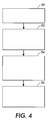
- Figure 4 shows a flow chart indicating steps for producing an image of a desired color on a substrate, according to the teachings of the present invention.
- Figure 5 is a flow chart describing a method for producing an image of a desired color on a substrate, according to the teachings of the present invention
- Image forming systems include electrophotographic, electrostatic or electrostatographic, ionographic, and other types of image forming or reproducing systems that are adapted to capture and/or store image data associated with a particular object, such as a document.
- the system of the present invention is intended to be implemented in a variety of environments, such as in any of the foregoing types of image forming systems, and is not limited to the specific systems described below.
- Pantone® inks Differences in the intrinsic properties of Pantone® inks can result in poor quality color prints. For example, differences in the toning rates, or plate-out rates, among the approximately fourteen Pantone® basic colors, which are mixed to produce over a thousand colors, cause the relative fraction of the basic colors on a substrate, such as paper, to deviate from a desired mixture.
- the difference in toning rates is mainly determined by the electrophoretic mobility of the toner particles.
- LID toner particles the pigmented resin imbedded with charge control agents (CCA) acquire their charges through charge exchange with the surrounding charge director micelles (counter ions).
- Pigment itself significantly affects the charging level and, therefore, the toner particle mobility and toning rates.
- Pantone® 347 a color whose hue is somewhat dark green, is a mixture of two Pantone® basic colors, "Pantone® Process Blue” and “Pantone® Yellow”, with a mass fraction of 62.5% and 37.5% respectively. Because of the variation in charging, the "blue” and the "yellow” particles have different mobilities and toning rates.
- Pantone® 347 ink is added to a sump and fed to a standard toning station, the out-coming color of the prints differ from the color of original Pantone® 347.
- the degree of deviation mostly depends on the difference in the mobility.
- the developability constant, K i of a given toner species i , is determined by the related process parameters, such as the local electrostatic field, and the duration of development time. Often, one can assume that the developability constant is constant across species, in which case the subscript can be dropped in favor of a constant K valid for all species.
- the mobility is determined by the charge of the particle as well as other variables, such as viscosity of the carrier fluid, and size of the toner particles.
- the image forming system 10 includes a replenishing source 12, an intermediate station 14, and a development station 16.
- the development station 16 transfers toner to the substrate, such as paper, for producing an image thereon.
- the development station 16 can undertake various processes for forming a latent charge image, including optical image projecting onto a charged photoconductive belt or drum, charging a dielectric member with an electrostatic pin array or electron beam, and charge projection from an ionographic print cartridge or from a plasma generator.
- the latent image may be transferred to an intermediate member before final development.
- the latent image may be developed on the same member as that on which it is formed, with different system architectures having evolved to address different process priorities, such as cost, speed, preferred type of toning system or intended receiving substrate.
- the replenishing source 12 contains a reservoir for storing toner.
- the replenishing source 12 supplies toner to the development station 16 via the intermediate station 14.
- the intermediate station 14 conditions and helps to regulate the color of the image produced on the substrate.
- the intermediate station 14 of the image forming system 10 is shown in more detail.
- the intermediate station 14 includes a conditioning station 18, or sump, which is coupled to a plate-out or drawing device 20 and a control device 22.
- the conditioning station 18 conditions the toner before transferring the toner to the development station 16.
- Toner conditioning and feeding to the development station 16 is commonly done gravitationally, or mechanically along with agitation to prevent agglomeration or lumping of toner particles. Such lumping makes it difficult to develop the image uniformly, detect the toner level, and can result in print deletions.
- a stream of gas may be used to convey the toner to different parts of the development station 16. The stream of gas helps prevent the toner from lumping.
- the drawing device 20 draws toner from the conditioning station 18 thereby shortening the time required for the toner concentrations to reach equilibrium in the development station 16, and helping to achieve better quality prints.
- the control device 22 is coupled to the drawing device 20 and sends a signal to the development station 16 to produce the image on the substrate if the drawn toner is within an acceptable color range.
- the control device 22 can include a processor and/or memory for initiating electronic signals that feed toner to the development station 16 once the toner drawn by the drawing device 20 is determined to be appropriate for producing the desired color.
- the drawing device 20 can consist of a pair of electrically conductive rollers with a potential difference across them. The potential difference creates an electric field whose direction can cause the charged liquid toner particles to migrate to the upper roll as shown in Fig.
- the deposited toner is measured colorimetrically and removed by a scraper blade.
- the control device 22 can include a microprocessor that monitors the colorimeter and signals the main machine controller that the ink was sufficiently conditioned to begin image development.
- the microprocessor also turns off the electric field in the drawing device when toner removal is not desired.
- the microprocessor can occasionally monitor the state of the ink and take corrective action if the colorimeter shows the ink to be outside of preset bounds.
- the drawing devices include electrode surfaces and make use of the application of an electric field to cause toner deposition. A pair of rotating rolls allows the use of a scraper blade for toner removal.
- each Pantone® ink mixture is essentially determined by the respective ratio defined above.
- Equations (5) and (7) imply that the concentrations in the conditioning station 14 eventually reach equilibrium, and that at equilibrium the print color is the same as that in the replenishing source 12, provided that a constant supply of the right Pantone® mixture is maintained, in accordance with Equation (3).
- the relaxation time is the time required for the color deviation to be within specifications. Before equilibrium is reached, prints produced by the development station 16 may not have acceptable colors, and are typically discarded by the user of the image forming system 10.
- the relaxation time, V / K ⁇ indicates that the smaller the sump or the larger the developability and toner mobility, the shorter the time required to achieve relaxation.
- FIG. 3A and 3B a schematic illustrating the operation of the drawing device 20 during the set-up and the operational modes is shown.
- a colorimeter 24 is coupled to the drawing device 20 and to the control device 22.
- a feed tube 26 transfers toner from the conditioning station 18 to the development station 16.
- the Pantone replenishing station 12 contains, and is replenished with, the desired Pantone ink mixture whose color becomes the print color on the substrate.
- the replenishing station 12 is connected to the conditioning station 18, which directly supplies the ink to the development station 16 for the final toning of the latent images.
- the conditioning station 18 serves the purpose of conditioning the Pantone mixture, in the setup mode shown in Fig. 3A, so the right ratio or color can be established before the ink is applied to the development station 16.
- the preferred operational mode shown in Fig. 3B is established.
- the sump concentration ratio, R s is maintained at the level defined in Eqs. (2) and (3), relative to the replenishing ratio, R r and the identical print ratio, R p .
- the conditioning is accomplished with the use of a drawing device 20, e.g., a pair of rotational rollers 28A and 28B, or other electrostatic development device.
- a drawing device 20 e.g., a pair of rotational rollers 28A and 28B, or other electrostatic development device.
- This device is distinct from the development station 16 where the final prints are generated.
- a portion of the original Pantone mixture is developed to one roller 28A of the drawing device 20 and discarded, and the remaining ink, carried by the other roller 28B, is fed back to the conditioning station 18, or sump. Since the sump volume, V , is relatively small, the equilibrium and the right mixture ratio is established rather quickly.
- a colorimeter 24 is used to monitor the plate-out color on the roller 28A. Only when the color plated out matches well with the intended print color, the setup mode shown in Fig.
- the "conditioned ink" in the ink conditioning station 18 can be further directed to the development station 16 for the final toning in the operational mode shown in Fig. 3B.
- the setup mode can be enhanced by operating the drawing device 20 so that the developabillty is maximized.
- a high field, high speed process combining with a wide development area e.g., long rollers
- This has the effect of shortening the setup time, V / K ⁇ , by reducing the sump volume, V . and increasing the developability, K .
- the ink conditioning station 18 can then be run in a continuous fashion during the printing process to continuously monitor and correct the conditioning sump concentration if required. This continuous monitoring is done at a reduced developability to conserve toner.
- Pantone 347 is made of the mixture of "Pantone Process Blue” and “Pantone Yellow” with a mass fraction of 62.5% and 37.5% respectively, that is, R p , and R r are 1.67.
- R p the "Pantone Process Blue” toner mobility
- Rs should be maintained at 0.83.
- more "Pantone Yellow” than the "Pantone Process Blue” is required in the conditioning station 16, opposite to the composition of Pantone 347 prescribed by conventional techniques.
- the excessive "Pantone Process Blue” is plated out and removed, while the remaining ink with higher content of the "Pantone Yellow” is fed back to the conditioning station 18.
- the color in the conditioning sump will change and eventually turn into a fixed color, indicating that equilibrium has been established.
- the color of the plate-out is monitored constantly, which enables an automatic switch from the setup mode of Fig. 3A to the regular operational mode of Fig. 3B soon after equilibrium is reached.
- An additional colorimeter can be used to measure the color of the toned image during the regular operational mode, and the conditioning station 18 can be re-activated if a growing color deviation is sensed from the prints.
- An apparatus that is similar to the conditioning station 18 can also be used as an individual device to determine the right "conditioned mixture” for any given Pantone color that meets the customer color requirement. That is, in addition to a specific Pantone ink that customers require, a separated batch of "conditioned ink,” or “conditioned premix,” automatically determined by such an apparatus, can be separately manufactured and provided to customers as well. Such a conditioned premix is poured into the conditioning station 18 in the customer's pantoning printers, resulting in minimum or no waste during the setup mode.
- the first several substrates are typically discarded because the image does not have the desired color.
- the present invention obviates the need to discard the first several substrates because after the set up mode is completed, a process that does not involve the discarding of substrates, the desired color is maintained in the images on the substrate.
- the set up mode, in which equilibrium is established can be completed expeditiously by decreasing the relaxation time V / K ⁇ .
- a flow chart is presented describing a method for producing an image of a desired color on a substrate.
- a conditioning station 18 is filled with a toner.
- a portion of the toner is drawn from the conditioning station 18 with the use of a drawing device 20.
- the portion of the toner is analyzed to determine whether the toner is suitable for producing the desired! color.
- a drawing device 20 having a first roller together with a colorimeter 24 can be used for this purpose.
- a sample of the portion of toner drawn by the drawing device 20 can be developed to the first roller, and its color measured by the colorimeter.
- the toner is fed to a development station 16 for producing the image of the desired color on the substrate.
- the toner solution contains a first solution of a first species and a second solution of a second species, the ratio of the first solution to the second solution being R p .
- a conditioning station 18 is filled with a sump toner solution containing the first colored solution and the second colored solution.
- the sump solution is fed to a development station 16 for forming the image on the substrate, wherein the ratio of the first colored solution to the second colored solution in the sump toner solution is substantially ( ⁇ 2 / ⁇ 1 ) R p .
- ⁇ 1 and ⁇ 2 are mobilities of the first species and the second species, respectively.
Landscapes
- Physics & Mathematics (AREA)
- General Physics & Mathematics (AREA)
- Color Electrophotography (AREA)
- Wet Developing In Electrophotography (AREA)
- Control Or Security For Electrophotography (AREA)
- Liquid Developers In Electrophotography (AREA)
Abstract
Description

Claims (10)
- An image forming system for producing an image of a desired color on a substrate, the system comprisinga conditioning station for conditioning a toner prior to forming the image on the substrate;a drawing device to draw a portion of the toner from the conditioning station; anda control device coupled to the drawing device for sending a signal to form the image on the substrate if the drawn toner is suitable for producing the desired color.
- The system of claim 1, further comprising a development station for transferring toner to the substrate.
- The system of claim 1, further comprising a replenishing source for supplying the toner to the conditioning station.
- The system of claim 1, further comprising a colorimeter for testing a color derived from the portion of the toner drawn from the conditioning station by the drawing device.
- The system of claim 1, wherein the drawing device includes at least one rotational roller to help draw the portion of the toner from the conditioning station.
- The system of claim 1, wherein the drawing device includes a first roller and a second roller such that a first sample of the portion of the toner drawn by the drawing device is developed using the first roller, and a second sample of the portion of the toner drawn by the drawing device is returned to the conditioning station by the second roller.
- A method for producing an image of a desired color on a substrate, the method comprising the steps of:filling a conditioning station with a toner;drawing a portion of the toner from the conditioning station;analyzing the portion of the toner to determine whether the toner is suitable for producing the desired color; andprovided the toner is suitable for producing the desired color, feeding the toner to a development station for producing the image of the desired color on the substrate.
- The method of claim 7, further comprising the step of ceasing to draw the portion prior to feeding the toner to the development station.
- The method of claim 7, wherein the portion of the toner is continuously drawn as the image of the desired color is being produced on the substrate.
- A method of forming an image of a desired color on a substrate utilizing a toner solution of the desired color containing a first solution of a first species and a second solution of a second species, the ratio of the first solution to the second solution being Rp, the method comprising the steps of:filling a conditioning station with a sump toner solution containing the first colored solution and the second colored solution; andfeeding the sump solution to a development station for forming the image on the substrate, wherein the ratio of the first colored solution to the second colored solution in the sump toner solution is substantially (µ2/µ1) Rp, where µ1 and µ2 are mobilities of the first species and the second species, respectively.
Applications Claiming Priority (2)
| Application Number | Priority Date | Filing Date | Title |
|---|---|---|---|
| US42003 | 2001-10-19 | ||
| US10/042,003 US6647220B2 (en) | 2001-10-19 | 2001-10-19 | System and method for conditioning a toner before development |
Publications (3)
| Publication Number | Publication Date |
|---|---|
| EP1304600A2 true EP1304600A2 (en) | 2003-04-23 |
| EP1304600A3 EP1304600A3 (en) | 2005-03-30 |
| EP1304600B1 EP1304600B1 (en) | 2007-12-19 |
Family
ID=21919521
Family Applications (1)
| Application Number | Title | Priority Date | Filing Date |
|---|---|---|---|
| EP02023408A Expired - Lifetime EP1304600B1 (en) | 2001-10-19 | 2002-10-18 | Systems and methods for liquid immersion development |
Country Status (4)
| Country | Link |
|---|---|
| US (1) | US6647220B2 (en) |
| EP (1) | EP1304600B1 (en) |
| JP (1) | JP4350355B2 (en) |
| DE (1) | DE60224150T2 (en) |
Families Citing this family (3)
| Publication number | Priority date | Publication date | Assignee | Title |
|---|---|---|---|---|
| US20070048020A1 (en) * | 2005-08-23 | 2007-03-01 | Xerox Corporation | Color order fulfilment method |
| AP2724A (en) | 2006-07-21 | 2013-08-31 | Xyleco Inc | Conversion systems for biomass |
| US8825408B2 (en) * | 2008-06-13 | 2014-09-02 | Schlumberger Technology Corporation | Using models for equilibrium distributions of asphaltenes in the prescence of GOR gradients to determine sampling procedures |
Family Cites Families (11)
| Publication number | Priority date | Publication date | Assignee | Title |
|---|---|---|---|---|
| JPS533348A (en) * | 1976-06-30 | 1978-01-13 | Konishiroku Photo Ind Co Ltd | Process and device for controlling toner density of developer liquid |
| US5369476A (en) * | 1992-01-28 | 1994-11-29 | Cactus | Toner control system and method for electrographic printing |
| US5557393A (en) * | 1994-11-04 | 1996-09-17 | Xerox Corporation | Process and apparatus for achieving customer selectable colors in an electrostatographic imaging system |
| US5781828A (en) * | 1996-09-26 | 1998-07-14 | Xerox Corporation | Liquid color mixing and replenishment system for an electrostatographic printing machine |
| US5713062A (en) * | 1996-09-26 | 1998-01-27 | Xerox Corporation | Color mixing and control system for use in an electrostatographic printing machine |
| US5897239A (en) * | 1997-03-31 | 1999-04-27 | Xerox Corporation | Photometric color correction and control system for custom colors |
| KR100269117B1 (en) * | 1997-07-16 | 2000-10-16 | 윤종용 | Apparatus for measuring concentration of developer |
| KR100327244B1 (en) * | 1998-12-28 | 2002-05-09 | 윤종용 | Developer concentration measurement device of wet press |
| EP1173796B1 (en) * | 1999-03-28 | 2004-05-12 | Hewlett-Packard Indigo B.V. | Method of mixing color toner |
| KR100374584B1 (en) * | 1999-05-31 | 2003-03-03 | 삼성전자주식회사 | Apparatus for measuring concentration of developer in liquid printer |
| JP2001201943A (en) * | 2000-01-17 | 2001-07-27 | Nec Niigata Ltd | Developer solution adjusting device for electrostatic and wet type electrophotographic printer |
-
2001
- 2001-10-19 US US10/042,003 patent/US6647220B2/en not_active Expired - Lifetime
-
2002
- 2002-10-15 JP JP2002299766A patent/JP4350355B2/en not_active Expired - Fee Related
- 2002-10-18 EP EP02023408A patent/EP1304600B1/en not_active Expired - Lifetime
- 2002-10-18 DE DE60224150T patent/DE60224150T2/en not_active Expired - Lifetime
Also Published As
| Publication number | Publication date |
|---|---|
| JP4350355B2 (en) | 2009-10-21 |
| DE60224150D1 (en) | 2008-01-31 |
| EP1304600B1 (en) | 2007-12-19 |
| US20030077090A1 (en) | 2003-04-24 |
| EP1304600A3 (en) | 2005-03-30 |
| JP2003177593A (en) | 2003-06-27 |
| US6647220B2 (en) | 2003-11-11 |
| DE60224150T2 (en) | 2008-04-17 |
Similar Documents
| Publication | Publication Date | Title |
|---|---|---|
| US6682865B2 (en) | Hybrid electrophotographic apparatus for custom color printing | |
| US6404997B1 (en) | Method and apparatus for dynamically controlling image density | |
| US7558516B2 (en) | Image forming apparatus wherein a carrier weight ratio in a first supply container and carrier weight ratio in a second supply container are substantially equal to each other | |
| JPH10104954A (en) | Developing system, developing device and printing method for electrostatic copying and printing machine | |
| US20100027035A1 (en) | Dynamic adjustable custom color printer and custom color images | |
| CN105425565A (en) | Image forming apparatus | |
| US6526244B1 (en) | Hybrid electrophotographic apparatus for custom color printing | |
| US6993272B2 (en) | Method of development of custom colors without changing developer housing | |
| US6647220B2 (en) | System and method for conditioning a toner before development | |
| US7151902B2 (en) | Toner transfer technique | |
| US20080044190A1 (en) | Developer dispense for enhanced stability in xerographic printing systems | |
| US8147026B2 (en) | Image quality matching in a mixed print engine assembly system | |
| US6618564B2 (en) | Electrophotographic development system with custom color printing | |
| US5512978A (en) | Replenishing system | |
| JP2002502505A (en) | Color control device for electronic recording printer | |
| EP0833219A1 (en) | Color mixing and control system for use in an electrostatographic printing machine | |
| EP0833220B1 (en) | Color mixing and control system for use in an electrostatographic printing machine | |
| US8620192B2 (en) | Dual toner replenisher assembly for continuously variable gloss | |
| JP2000056578A (en) | Wet image forming apparatus | |
| KR20140081673A (en) | System and apparatus for toner charging using charge/metering blade having an adjustable nip | |
| US20100271643A1 (en) | Image quality matching in a print engine assembly system | |
| US20210302877A1 (en) | Binary ink developers | |
| JPH0527524A (en) | Image forming device |
Legal Events
| Date | Code | Title | Description |
|---|---|---|---|
| PUAI | Public reference made under article 153(3) epc to a published international application that has entered the european phase |
Free format text: ORIGINAL CODE: 0009012 |
|
| AK | Designated contracting states |
Designated state(s): AT BE BG CH CY CZ DE DK EE ES FI FR GB GR IE IT LI LU MC NL PT SE SK TR |
|
| AX | Request for extension of the european patent |
Extension state: AL LT LV MK RO SI |
|
| PUAL | Search report despatched |
Free format text: ORIGINAL CODE: 0009013 |
|
| AK | Designated contracting states |
Kind code of ref document: A3 Designated state(s): AT BE BG CH CY CZ DE DK EE ES FI FR GB GR IE IT LI LU MC NL PT SE SK TR |
|
| AX | Request for extension of the european patent |
Extension state: AL LT LV MK RO SI |
|
| 17P | Request for examination filed |
Effective date: 20050930 |
|
| AKX | Designation fees paid |
Designated state(s): DE FR GB |
|
| GRAP | Despatch of communication of intention to grant a patent |
Free format text: ORIGINAL CODE: EPIDOSNIGR1 |
|
| GRAS | Grant fee paid |
Free format text: ORIGINAL CODE: EPIDOSNIGR3 |
|
| GRAA | (expected) grant |
Free format text: ORIGINAL CODE: 0009210 |
|
| AK | Designated contracting states |
Kind code of ref document: B1 Designated state(s): DE FR GB |
|
| REG | Reference to a national code |
Ref country code: GB Ref legal event code: FG4D |
|
| REF | Corresponds to: |
Ref document number: 60224150 Country of ref document: DE Date of ref document: 20080131 Kind code of ref document: P |
|
| ET | Fr: translation filed | ||
| PLBE | No opposition filed within time limit |
Free format text: ORIGINAL CODE: 0009261 |
|
| STAA | Information on the status of an ep patent application or granted ep patent |
Free format text: STATUS: NO OPPOSITION FILED WITHIN TIME LIMIT |
|
| 26N | No opposition filed |
Effective date: 20080922 |
|
| REG | Reference to a national code |
Ref country code: FR Ref legal event code: PLFP Year of fee payment: 15 |
|
| REG | Reference to a national code |
Ref country code: FR Ref legal event code: PLFP Year of fee payment: 16 |
|
| REG | Reference to a national code |
Ref country code: FR Ref legal event code: PLFP Year of fee payment: 17 |
|
| PGFP | Annual fee paid to national office [announced via postgrant information from national office to epo] |
Ref country code: FR Payment date: 20180920 Year of fee payment: 17 |
|
| PGFP | Annual fee paid to national office [announced via postgrant information from national office to epo] |
Ref country code: GB Payment date: 20180925 Year of fee payment: 17 |
|
| PGFP | Annual fee paid to national office [announced via postgrant information from national office to epo] |
Ref country code: DE Payment date: 20180819 Year of fee payment: 17 |
|
| REG | Reference to a national code |
Ref country code: DE Ref legal event code: R119 Ref document number: 60224150 Country of ref document: DE |
|
| PG25 | Lapsed in a contracting state [announced via postgrant information from national office to epo] |
Ref country code: DE Free format text: LAPSE BECAUSE OF NON-PAYMENT OF DUE FEES Effective date: 20200501 |
|
| GBPC | Gb: european patent ceased through non-payment of renewal fee |
Effective date: 20191018 |
|
| PG25 | Lapsed in a contracting state [announced via postgrant information from national office to epo] |
Ref country code: FR Free format text: LAPSE BECAUSE OF NON-PAYMENT OF DUE FEES Effective date: 20191031 Ref country code: GB Free format text: LAPSE BECAUSE OF NON-PAYMENT OF DUE FEES Effective date: 20191018 |