EP1304514A1 - Weep plug - Google Patents
Weep plug Download PDFInfo
- Publication number
- EP1304514A1 EP1304514A1 EP02257212A EP02257212A EP1304514A1 EP 1304514 A1 EP1304514 A1 EP 1304514A1 EP 02257212 A EP02257212 A EP 02257212A EP 02257212 A EP02257212 A EP 02257212A EP 1304514 A1 EP1304514 A1 EP 1304514A1
- Authority
- EP
- European Patent Office
- Prior art keywords
- weep
- plug
- wall
- generally
- weep plug
- Prior art date
- Legal status (The legal status is an assumption and is not a legal conclusion. Google has not performed a legal analysis and makes no representation as to the accuracy of the status listed.)
- Granted
Links
- 239000003921 oil Substances 0.000 description 26
- 239000007789 gas Substances 0.000 description 12
- 239000000463 material Substances 0.000 description 7
- 239000000203 mixture Substances 0.000 description 5
- 238000000034 method Methods 0.000 description 4
- 239000000567 combustion gas Substances 0.000 description 3
- 239000010687 lubricating oil Substances 0.000 description 3
- 239000004696 Poly ether ether ketone Substances 0.000 description 2
- 238000000151 deposition Methods 0.000 description 2
- 239000000284 extract Substances 0.000 description 2
- 239000000446 fuel Substances 0.000 description 2
- 238000009434 installation Methods 0.000 description 2
- 238000003754 machining Methods 0.000 description 2
- 229920002530 polyetherether ketone Polymers 0.000 description 2
- 229920000642 polymer Polymers 0.000 description 2
- 239000004642 Polyimide Substances 0.000 description 1
- 229920004695 VICTREX™ PEEK Polymers 0.000 description 1
- 229910052782 aluminium Inorganic materials 0.000 description 1
- XAGFODPZIPBFFR-UHFFFAOYSA-N aluminium Chemical compound [Al] XAGFODPZIPBFFR-UHFFFAOYSA-N 0.000 description 1
- JUPQTSLXMOCDHR-UHFFFAOYSA-N benzene-1,4-diol;bis(4-fluorophenyl)methanone Chemical compound OC1=CC=C(O)C=C1.C1=CC(F)=CC=C1C(=O)C1=CC=C(F)C=C1 JUPQTSLXMOCDHR-UHFFFAOYSA-N 0.000 description 1
- 238000000748 compression moulding Methods 0.000 description 1
- 230000001010 compromised effect Effects 0.000 description 1
- 238000001746 injection moulding Methods 0.000 description 1
- 238000004519 manufacturing process Methods 0.000 description 1
- 229910052751 metal Inorganic materials 0.000 description 1
- 239000002184 metal Substances 0.000 description 1
- 150000002739 metals Chemical class 0.000 description 1
- 239000010705 motor oil Substances 0.000 description 1
- 238000013021 overheating Methods 0.000 description 1
- 239000002245 particle Substances 0.000 description 1
- 229920003223 poly(pyromellitimide-1,4-diphenyl ether) Polymers 0.000 description 1
- 229920001721 polyimide Polymers 0.000 description 1
- 230000001141 propulsive effect Effects 0.000 description 1
- 238000011084 recovery Methods 0.000 description 1
- 238000007789 sealing Methods 0.000 description 1
Images


Classifications
-
- F—MECHANICAL ENGINEERING; LIGHTING; HEATING; WEAPONS; BLASTING
- F01—MACHINES OR ENGINES IN GENERAL; ENGINE PLANTS IN GENERAL; STEAM ENGINES
- F01M—LUBRICATING OF MACHINES OR ENGINES IN GENERAL; LUBRICATING INTERNAL COMBUSTION ENGINES; CRANKCASE VENTILATING
- F01M13/00—Crankcase ventilating or breathing
- F01M13/04—Crankcase ventilating or breathing having means for purifying air before leaving crankcase, e.g. removing oil
- F01M13/0405—Crankcase ventilating or breathing having means for purifying air before leaving crankcase, e.g. removing oil arranged in covering members apertures, e.g. caps
-
- F—MECHANICAL ENGINEERING; LIGHTING; HEATING; WEAPONS; BLASTING
- F05—INDEXING SCHEMES RELATING TO ENGINES OR PUMPS IN VARIOUS SUBCLASSES OF CLASSES F01-F04
- F05B—INDEXING SCHEME RELATING TO WIND, SPRING, WEIGHT, INERTIA OR LIKE MOTORS, TO MACHINES OR ENGINES FOR LIQUIDS COVERED BY SUBCLASSES F03B, F03D AND F03G
- F05B2260/00—Function
- F05B2260/60—Fluid transfer
- F05B2260/602—Drainage
Definitions
- This invention relates generally to gas turbine engines and more particularly to a weep plug for recovering oil used to lubricate the bearings of a gas turbine engine.
- Gas turbine engines typically include a core having a compressor for compressing air entering the core, a combustor where fuel is mixed with the compressed air and then burned to create a high energy gas stream, and a pressure turbine which extracts energy from the gas stream to drive the compressor.
- a low pressure turbine located downstream from the core extracts more energy from the gas stream for driving a fan. The fan provides the main propulsive thrust generated by the engine.
- lubricating oil and seals In order to prevent overheating of the bearings, lubricating oil and seals must be provided to prevent the hot air in the engine flowpath from reaching the bearing sumps, and lubricating oil flows must be sufficient to carry away heat generated internally by the bearings because of their high relative speed of rotation.
- Oil consumption arises from the method used to seal the engine sumps.
- the sealing method makes it necessary for an air flow circuit to exist that flows into and out of the sumps. This flow ultimately contains oil that is unrecoverable unless adequately separated and delivered back to the sumps.
- the forward engine sump is vented through the forward fan shaft and out the engine through a center vent tube. Once the air/oil mixture exits the sump, it swirls, depositing oil on the inside of the fan shaft. Oil that is contained in the air/oil mixture is lost when it is unable to centrifuge back into the sump through the vent hole due to rapidly escaping vent air.
- weep holes are passages whose function is to provide a dedicated path for oil to re-enter the sump, integrated into the forward fan shaft design.
- Weep holes are typically smaller in diameter and longer in length than holes designed to route vent flow.
- the fan shaft has no dedicated weep holes, only vent holes. Forming weep holes in fan shafts of the latter design after their manufacture and installation in an engine would be prohibitively expensive.
- the present invention provides a weep plug having a central vent passage and one or more weep passages parallel to the central passage.
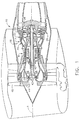
- Figure 1 illustrates a gas turbine engine, generally designated 10, in which is incorporated weep plug 90 of the present invention, as shown in detail in Figures 3-8.
- the engine 10 has a longitudinal center line or axis A and an outer stationary annular casing 14 disposed concentrically about and coaxially along the axis A.
- the engine 10 includes a gas generator core 16 which is composed of a multi-stage compressor 18, a combustor 20, and a high pressure turbine 22, either single or multiple stage, all arranged coaxially about the longitudinal axis or center line A of the engine 10 in a serial, axial flow relationship.
- An annular outer drive shaft 24 fixedly interconnects the compressor 18 and high pressure turbine 22.
- the core 16 is effective for generating combustion gases. Pressurized air from the compressor 18 is mixed with fuel in the combustor 20 and ignited, thereby generating combustion gases. Some work is extracted from these gases by the high pressure turbine 22 which drives the compressor 18. The remainder of the combustion gases are discharged from the core 16 into a low pressure turbine 26.
- An inner drive shaft 38 is mounted for rotation relative to the outer drive shaft 24 via rear bearings 32, differential bearings 40, and via suitable forward bearings 42 interconnected to the outer stationary casing 14.
- the inner drive shaft 38 rotatably drives a forward fan shaft 62, which in turn drives a forward fan disk/booster rotor 44.
- Fan blades 48 and booster blades 54 are mounted to the fan disk/booster rotor 44 for rotation therewith.
- the bearing sump 58 is generally defined by an outer annular structure 60 which is interconnected to the outer casing 14 and the forward fan shaft 62 which rigidly interconnects the forward end of the inner drive shaft 38 to the forward fan disk/booster rotor 44.
- the forward fan shaft 62 being connected with an inner annular race 42A of the forward bearings, 42 rotates with the inner drive shaft 38 relative to the stationary outer annular structure 60 of the bearing sump 58 which is connected to an outer annular race 42B of the forward bearings 42.
- Conventional labyrinth air and oil seals 64, 66 are provided adjacent to the forward bearings 42 and between the forward ends of the relatively rotating outer annular structure 60 and the forward fan shaft 62 to seal the forward end of the bearing sump 58. Oil is pumped to the forward bearings 42 and therefore into the sump 58 through an oil supply conduit 68. Pressurized air is injected to the labyrinth air seal 64 through an air supply conduit 70 in order to prevent oil from leaking through the labyrinth oil seal 66.
- the forward fan shaft 62 has one or more vent holes 84 extending through its thickness in a generally radial direction. Typically, the fan shaft 62 has a plurality of these holes 84 arranged in a band around its circumference.
- the vent holes 84 provide a passage for air flow from the sump 58 into a vent plenum 78 and subsequently into the center vent tube 80.
- a cover 74 is attached to the forward fan shaft 62 with fasteners 76.
- a weep plug 90 has a unitary body 92 having a first end 96 and a second end 98, defining an axis 94 extending therebetween.
- a generally cylindrical central passage 100 passes axially through the body 92 from the first end 96 to the second end 98.
- a generally circular head 116 having a flat end surface 118 is disposed at the first end 96.
- Adjacent the head 116 is a generally annular flange 104 which has a pair of opposed flats 108 formed on laterally opposite sides thereof.
- An annular groove 117 separates the circular head 116 and the flange 104 and provides a surface for a tool to pry against when removing the plug 90.
- a generally cylindrical elongated portion 102 extends between a proximate end 110 adjacent the flange 104 and a distal end 112 at the second end 98 of the body 92.
- An annular groove 114 disposed at the junction of the elongated portion 102 and the flange 104.
- a rim 106 is disposed on the flange 104 and extends axially towards the second end 98 of the body 92.
- the rim 106 is divided into two annular sections by the presence of the opposed flats 108 of the flange 104.
- the flats 108 provide a clearance space between the weep plug 90 and other nearby structures when the weep plug 90 is installed.
- a pair of slots 122 are formed in opposite sides of the elongated portion 102.
- the slots 122 begin at the distal end 112 of the elongated portion 102 and extend partially down the length of the elongated section 94.
- the slots 122 divide the elongated portion 102 into two prongs 124.
- Each of the prongs 124 has a pair of chamfered surfaces 120 formed at its distal end 112, on opposite sides of the prong 124.
- An annular protruding lip 126 extends from the distal end 112 of each of the prongs 108.
- At least one weep passage 130 is formed in the outer surface 128 of the elongated portion 102.
- the weep passages 130 are in the form of grooves having a generally semicircular cross-section, although other shapes may be used.
- the weep passages have an outlet 132 disposed at the distal end of the elongated portion 102.
- the weep passages then extend axially towards the flange 104.
- the weep passages 130 intersect the annular groove 114, they turn at a corner 134 and then extend radially outward, terminating at an inlet 136 disposed in the flange 104, in alignment with the flat 108.
- the weep plug 90 is manufactured from a material which is capable of withstanding the temperatures prevailing in the sump 58, which is approximately 149°C (300°F), and resisting attack from the engine lubricating oil. Also, because the fan shaft 62 is a life-limited part whose characteristics must not be compromised, the plug 90 must be made of a material which will itself wear rather than cause wear of the fan shaft 62. Furthermore, the weight of the plug 90 is preferably minimized both to avoid extra weight in the engine 10 generally, and to preclude imbalance problems in the fan shaft 62, especially if the plugs 90 should be improperly installed.
- One suitable material is VESPEL polyimide, available from E.I. DuPont de Nemours and Company, Wilmington, DE 19898 USA.
- PEEK polyetheretherketone Another suitable material is PEEK polyetheretherketone, which is available from Victrex USA Inc., 3 Caledon Court, Suite A, Greenville, SC 29615 USA.
- any material that satisfies the requirements described above may be used, for example aluminum or other relatively soft metals may also be suitable materials.
- the weep plug 90 may be formed by any known method, for example injection molding, compression molding a near-net shape followed by machining, or by machining from a blank of material.
- a weep plug 290 is similar to weep plug 90, having a body 292 comprising an elongated portion 102, a flange 104 having a rim 106, and a circular head 116.
- An annular groove 114 encircles the body 292 at the junction of the flange 104 and the elongated portion 102.
- a pair of weep passages 294 are disposed in the outer surface of elongated portion 102 on opposite sides thereof. In this embodiment, the inlets 296 of the weep passages 294 do not extend into the flange 104.
- the flange 104 extends completely around the circumference of the body 292.
- a pair of opposed channels 298 are formed in the rim 106. The channels 298 are recessed from the surface of the rim 106 and provide additional area for oil to flow to the groove 114 and the weep passages 294.
- Figure 8 illustrates a more detailed view of the weep plug 90 installed in the forward fan shaft 62.
- the weep plug 90 is installed in the vent hole 84 from the radially inner direction.
- the chamfered surfaces 120 assist in aligning the body 92 of the weep plug 90 with the vent hole 84.
- the width W ( Figure 4) across the outer edges of the lips 126 is slightly greater than the diameter D ( Figure 2) of the vent hole 84.
- the presence of the slots 122 allows the prongs 124 to flex inward slightly as the weep plug 90 is installed.
- the weep plug 90 When the weep plug 90 is fully inserted and the lips 126 clear the radially outward edge of the vent hole 84, the prongs return to their original position and bear against the radially outer edge 302 of the vent hole 84, retaining the weep plug 90 in the vent hole 84.
- the weep plug 90 rotates with the forward fan shaft 62 and tends to move radially outward. This causes the rim 106 of the flange 104 to bear against the radially inner edge 300 of the vent hole 84 and retain the weep plug 90 in the vent passage.
- an air/oil mixture exits the sump 58 through the central passage 100 of the weep plug 90, as shown by the arrows marked B in Figure 8.
- the length L of the weep plug 90 is about 30.5 mm (1.2 in.) and the diameter c of the central passage is about 8.8 mm (0.35 in.), resulting in a length-to-diameter ratio of about 3.5.
- the mixture then swirls, depositing oil on the inside of the forward fan shaft 62. Oil that is contained in the air/oil mixture flows into the inlets 136 of the weep passages 130, along the length of the weep passages 130, and then through the outlets 132 into the sump 58 where it can be recovered, as shown by arrows C.
- the weep passages 130 have a length I of about 21 mm (0.83 in.) and a width W of about 0.76 mm (0.03 in.), resulting in a length-to-diameter ratio of about 28.
- This greater L/D ratio allows the oil to flow up the weep passages 130 without being affected by the flow of air sump 58, as it would be without the weep plug 90.
- the diameter d of the elongated portion 102 of the weep plug 90 may be selected relative to the diameter D of the vent hole 84 to leave a clearance between the vent hole 84 and the plug body 92, creating an additional annulus for oil to centrifuge through without being sheared by escaping vent air.
- the diametrical clearance of the illustrated example is about 0.177 mm (0.007 in.).
- the weep plug 90 as disclosed herein provides a tangible oil consumption benefit and is yet simple to implement.
- the weep plugs 90 can be assembled on field engines while they are still mounted on the aircraft with very little disassembly of the engine. In one particular example, the assembly of four plugs into the forward fan shaft in a total of 22 holes resulted in about an 8% reduction in overall engine oil consumption.
- the optimum number of plugs 90 will vary for each particular application. If there are too few plugs , the benefit of reduced oil consumption will not be realized. If too many plugs are used they may excessively restrict the flow through vent holes 84, upsetting the sump pressurization balance.
- weep plug having a central vent passage and one or more weep passages.
Landscapes
- Engineering & Computer Science (AREA)
- Mechanical Engineering (AREA)
- General Engineering & Computer Science (AREA)
- Turbine Rotor Nozzle Sealing (AREA)
- Lubrication Details And Ventilation Of Internal Combustion Engines (AREA)
- Structures Of Non-Positive Displacement Pumps (AREA)
- General Details Of Gearings (AREA)
- Storage Of Web-Like Or Filamentary Materials (AREA)
- Removal Of Floating Material (AREA)
Abstract
Description
- This invention relates generally to gas turbine engines and more particularly to a weep plug for recovering oil used to lubricate the bearings of a gas turbine engine.
- Gas turbine engines typically include a core having a compressor for compressing air entering the core, a combustor where fuel is mixed with the compressed air and then burned to create a high energy gas stream, and a pressure turbine which extracts energy from the gas stream to drive the compressor. In aircraft turbofan engines, a low pressure turbine located downstream from the core extracts more energy from the gas stream for driving a fan. The fan provides the main propulsive thrust generated by the engine.
- Bearings are used in the engine to accurately locate and rotatably mount rotors with respect to stators in the compressor and high and low pressure turbines of the engine. The bearings are enclosed in oil-wetted portions of the engine called sumps.
- In order to prevent overheating of the bearings, lubricating oil and seals must be provided to prevent the hot air in the engine flowpath from reaching the bearing sumps, and lubricating oil flows must be sufficient to carry away heat generated internally by the bearings because of their high relative speed of rotation.
- Oil consumption arises from the method used to seal the engine sumps. The sealing method makes it necessary for an air flow circuit to exist that flows into and out of the sumps. This flow ultimately contains oil that is unrecoverable unless adequately separated and delivered back to the sumps. In one particular configuration the forward engine sump is vented through the forward fan shaft and out the engine through a center vent tube. Once the air/oil mixture exits the sump, it swirls, depositing oil on the inside of the fan shaft. Oil that is contained in the air/oil mixture is lost when it is unable to centrifuge back into the sump through the vent hole due to rapidly escaping vent air.
- Some designs allow for oil recovery by using weep holes, which are passages whose function is to provide a dedicated path for oil to re-enter the sump, integrated into the forward fan shaft design. Weep holes are typically smaller in diameter and longer in length than holes designed to route vent flow. However, in other designs, the fan shaft has no dedicated weep holes, only vent holes. Forming weep holes in fan shafts of the latter design after their manufacture and installation in an engine would be prohibitively expensive.
- Accordingly, there is a need for a method to recover oil in existing sump structures without modifying the existing hardware.
- The above-mentioned need is met by the present invention, which provides a weep plug having a central vent passage and one or more weep passages parallel to the central passage.
- The invention will now be described in greater detail, by way of example, with reference to the drawings, in which:-
- Figure 1 is a longitudinal axial sectional view of a gas turbine engine incorporating a weep plug of the present invention.
- Figure 2 is an enlarged fragmentary view of a region of the engine enclosed by dashed box 2-2 of Figure 1.
- Figure 3 is a perspective view of a weep plug of the present invention.
- Figure 4 is an end view of a weep plug of the present invention.
- Figure 5 is a side elevational view of the weep plug of Figure 4.
- Figure 6 is a cross-sectional view taken along lines 6-6 of Figure 5.
- Figure 7 is a perspective view of a weep plug constructed in accordance with an alternate embodiment of the present invention.
- Figure 8 is a cross-sectional view of a portion of a gas turbine engine fan forward shaft having a weep plug of the present invention installed therein.
-
- Referring to the drawings wherein identical reference numerals denote the same elements throughout the various views, Figure 1 illustrates a gas turbine engine, generally designated 10, in which is incorporated
weep plug 90 of the present invention, as shown in detail in Figures 3-8. Theengine 10 has a longitudinal center line or axis A and an outer stationaryannular casing 14 disposed concentrically about and coaxially along the axis A. Theengine 10 includes agas generator core 16 which is composed of amulti-stage compressor 18, acombustor 20, and a high pressure turbine 22, either single or multiple stage, all arranged coaxially about the longitudinal axis or center line A of theengine 10 in a serial, axial flow relationship. An annularouter drive shaft 24 fixedly interconnects thecompressor 18 and high pressure turbine 22. - The
core 16 is effective for generating combustion gases. Pressurized air from thecompressor 18 is mixed with fuel in thecombustor 20 and ignited, thereby generating combustion gases. Some work is extracted from these gases by the high pressure turbine 22 which drives thecompressor 18. The remainder of the combustion gases are discharged from thecore 16 into alow pressure turbine 26. - An
inner drive shaft 38 is mounted for rotation relative to theouter drive shaft 24 via rear bearings 32,differential bearings 40, and via suitableforward bearings 42 interconnected to the outerstationary casing 14. Theinner drive shaft 38, in turn, rotatably drives aforward fan shaft 62, which in turn drives a forward fan disk/booster rotor 44.Fan blades 48 and booster blades 54 are mounted to the fan disk/booster rotor 44 for rotation therewith. - Referring now to Figure 2, there is illustrated the region of the
gas turbine engine 10 where aconventional bearing sump 58 is defined about theforward bearings 42. Thebearing sump 58 is generally defined by an outerannular structure 60 which is interconnected to theouter casing 14 and theforward fan shaft 62 which rigidly interconnects the forward end of theinner drive shaft 38 to the forward fan disk/booster rotor 44. Theforward fan shaft 62, being connected with an innerannular race 42A of the forward bearings, 42 rotates with theinner drive shaft 38 relative to the stationary outerannular structure 60 of thebearing sump 58 which is connected to an outerannular race 42B of theforward bearings 42. - Conventional labyrinth air and
oil seals forward bearings 42 and between the forward ends of the relatively rotating outerannular structure 60 and theforward fan shaft 62 to seal the forward end of thebearing sump 58. Oil is pumped to theforward bearings 42 and therefore into thesump 58 through anoil supply conduit 68. Pressurized air is injected to thelabyrinth air seal 64 through anair supply conduit 70 in order to prevent oil from leaking through thelabyrinth oil seal 66. - A portion of the injected pressurized air which enters the
bearing sump 58 must be vented from thesump 58 in a controlled manner in order to maintain sump pressure at a proper balance. However, the pressurized air becomes mixed with particles of the oil in thesump 58. Therefore, theforward fan shaft 62 has one ormore vent holes 84 extending through its thickness in a generally radial direction. Typically, thefan shaft 62 has a plurality of theseholes 84 arranged in a band around its circumference. Thevent holes 84 provide a passage for air flow from thesump 58 into avent plenum 78 and subsequently into thecenter vent tube 80. A cover 74 is attached to theforward fan shaft 62 withfasteners 76. - Referring now to Figures 3-6, a
weep plug 90 has aunitary body 92 having afirst end 96 and asecond end 98, defining anaxis 94 extending therebetween. A generally cylindricalcentral passage 100 passes axially through thebody 92 from thefirst end 96 to thesecond end 98. A generallycircular head 116 having aflat end surface 118 is disposed at thefirst end 96. Adjacent thehead 116 is a generallyannular flange 104 which has a pair ofopposed flats 108 formed on laterally opposite sides thereof. Anannular groove 117 separates thecircular head 116 and theflange 104 and provides a surface for a tool to pry against when removing theplug 90. A generally cylindricalelongated portion 102 extends between aproximate end 110 adjacent theflange 104 and adistal end 112 at thesecond end 98 of thebody 92. Anannular groove 114 disposed at the junction of theelongated portion 102 and theflange 104. Arim 106 is disposed on theflange 104 and extends axially towards thesecond end 98 of thebody 92. Therim 106 is divided into two annular sections by the presence of theopposed flats 108 of theflange 104. Theflats 108 provide a clearance space between theweep plug 90 and other nearby structures when theweep plug 90 is installed. - A pair of
slots 122 are formed in opposite sides of theelongated portion 102. Theslots 122 begin at thedistal end 112 of theelongated portion 102 and extend partially down the length of theelongated section 94. Theslots 122 divide theelongated portion 102 into two prongs 124. Each of the prongs 124 has a pair ofchamfered surfaces 120 formed at itsdistal end 112, on opposite sides of the prong 124. An annularprotruding lip 126 extends from thedistal end 112 of each of theprongs 108. Although the illustrated example shows twoslots 122, it should be noted that three ormore slots 122 could be formed in theelongated portion 102, dividing it into three ormore prongs 108. At least one weeppassage 130 is formed in theouter surface 128 of theelongated portion 102. As best seen in Figures 4 and 5, in the illustrated example the weeppassages 130 are in the form of grooves having a generally semicircular cross-section, although other shapes may be used. The weep passages have anoutlet 132 disposed at the distal end of theelongated portion 102. The weep passages then extend axially towards theflange 104. At the point where the weeppassages 130 intersect theannular groove 114, they turn at acorner 134 and then extend radially outward, terminating at aninlet 136 disposed in theflange 104, in alignment with the flat 108. - The weep
plug 90 is manufactured from a material which is capable of withstanding the temperatures prevailing in thesump 58, which is approximately 149°C (300°F), and resisting attack from the engine lubricating oil. Also, because thefan shaft 62 is a life-limited part whose characteristics must not be compromised, theplug 90 must be made of a material which will itself wear rather than cause wear of thefan shaft 62. Furthermore, the weight of theplug 90 is preferably minimized both to avoid extra weight in theengine 10 generally, and to preclude imbalance problems in thefan shaft 62, especially if theplugs 90 should be improperly installed. One suitable material is VESPEL polyimide, available from E.I. DuPont de Nemours and Company, Wilmington, DE 19898 USA. Another suitable material is PEEK polyetheretherketone, which is available from Victrex USA Inc., 3 Caledon Court, Suite A, Greenville, SC 29615 USA. In general, any material that satisfies the requirements described above may be used, for example aluminum or other relatively soft metals may also be suitable materials. The weepplug 90 may be formed by any known method, for example injection molding, compression molding a near-net shape followed by machining, or by machining from a blank of material. - Another embodiment of the present invention is illustrated in Figure 7. A weep
plug 290 is similar to weepplug 90, having abody 292 comprising anelongated portion 102, aflange 104 having arim 106, and acircular head 116. Anannular groove 114 encircles thebody 292 at the junction of theflange 104 and theelongated portion 102. A pair of weeppassages 294 are disposed in the outer surface ofelongated portion 102 on opposite sides thereof. In this embodiment, theinlets 296 of the weeppassages 294 do not extend into theflange 104. Theflange 104 extends completely around the circumference of thebody 292. A pair ofopposed channels 298 are formed in therim 106. Thechannels 298 are recessed from the surface of therim 106 and provide additional area for oil to flow to thegroove 114 and the weeppassages 294. - Figure 8 illustrates a more detailed view of the weep
plug 90 installed in theforward fan shaft 62. The weepplug 90 is installed in thevent hole 84 from the radially inner direction. The chamfered surfaces 120 assist in aligning thebody 92 of the weepplug 90 with thevent hole 84. In the uninstalled condition the width W (Figure 4) across the outer edges of thelips 126 is slightly greater than the diameter D (Figure 2) of thevent hole 84. The presence of theslots 122 allows the prongs 124 to flex inward slightly as the weepplug 90 is installed. When the weepplug 90 is fully inserted and thelips 126 clear the radially outward edge of thevent hole 84, the prongs return to their original position and bear against the radiallyouter edge 302 of thevent hole 84, retaining the weepplug 90 in thevent hole 84. In operation, the weepplug 90 rotates with theforward fan shaft 62 and tends to move radially outward. This causes therim 106 of theflange 104 to bear against the radiallyinner edge 300 of thevent hole 84 and retain the weepplug 90 in the vent passage. - In operation, an air/oil mixture exits the
sump 58 through thecentral passage 100 of the weepplug 90, as shown by the arrows marked B in Figure 8. In the illustrated example the length L of the weepplug 90 is about 30.5 mm (1.2 in.) and the diameter c of the central passage is about 8.8 mm (0.35 in.), resulting in a length-to-diameter ratio of about 3.5. The mixture then swirls, depositing oil on the inside of theforward fan shaft 62. Oil that is contained in the air/oil mixture flows into theinlets 136 of the weeppassages 130, along the length of the weeppassages 130, and then through theoutlets 132 into thesump 58 where it can be recovered, as shown by arrows C. In the illustrated example the weeppassages 130 have a length I of about 21 mm (0.83 in.) and a width W of about 0.76 mm (0.03 in.), resulting in a length-to-diameter ratio of about 28. This greater L/D ratio allows the oil to flow up the weeppassages 130 without being affected by the flow ofair sump 58, as it would be without the weepplug 90. Additionally, the diameter d of theelongated portion 102 of the weepplug 90 may be selected relative to the diameter D of thevent hole 84 to leave a clearance between thevent hole 84 and theplug body 92, creating an additional annulus for oil to centrifuge through without being sheared by escaping vent air. The diametrical clearance of the illustrated example is about 0.177 mm (0.007 in.). - The weep
plug 90 as disclosed herein provides a tangible oil consumption benefit and is yet simple to implement. The weep plugs 90 can be assembled on field engines while they are still mounted on the aircraft with very little disassembly of the engine. In one particular example, the assembly of four plugs into the forward fan shaft in a total of 22 holes resulted in about an 8% reduction in overall engine oil consumption. The optimum number ofplugs 90 will vary for each particular application. If there are too few plugs , the benefit of reduced oil consumption will not be realized. If too many plugs are used they may excessively restrict the flow through vent holes 84, upsetting the sump pressurization balance. Analysis of another possible configuration has shown that 12 plugs used in a possible of 20 holes would result in the optimum reduction in oil consumption while minimally affecting engine system pressurization characteristics. It might also be desirable to use a reduced number of plugs, for example 10, or the equivalent of one plug every other hole, to provide simplified installation. - The foregoing has described a weep plug having a central vent passage and one or more weep passages.
- For the sake of good order, various aspects of the invention are set out in the following clauses:-
- 1. A weep plug (90) comprising:
- a generally cylindrical body (92) having first (96) and second (98) ends, a longitudinal axis (94), and a wall, said wall having inner and outer surfaces, said inner surface defining a central passage (100);
- a flange (104) disposed adjacent said first end (96); and
- at least one generally axial weep passage (130) disposed in said outer surface (128) of said wall, said weep passage (130) extending from said flange (104) to said second end (98).
- 2. The weep plug (90) of clause 1 further comprising at least one generally annular lip (126) extending radially outwardly from said outer surface (128) of said wall at said second end (98) thereof.
- 3. The weep plug (90) of clause 2 further comprising at least two generally axial slots (122) disposed in said wall at said second end (98) of said weep plug (90), said slots (122) dividing a portion of said wall into at least two axially extending prongs (124).
- 4. The weep plug (90) of clause 3 wherein each of said prongs (124) has a pair of chamfered surfaces (120) formed on opposite sides thereof at said second end (98).
- 5. The weep plug (90) of clause 2 further comprising a generally circular head (116) formed at said first end (96) of said weep plug (90), said generally circular head (116) separated from said flange (104) by a generally annular groove.
- 6. The weep plug (90) of clause 2 wherein said weep plug (90) comprises a polymer.
- 7. The weep plug (90) of clause 2 wherein said flange (104) comprises a generally annular rim facing said second end (98) of said weep plug (90) and further comprising a pair of recesses formed in said rim so as to define opposed channels (298), said channels (298) extending generally perpendicularly to said longitudinal axis (94).
- 8. The weep plug (90) of clause 2 wherein said flange (104) has recesses formed therein so as to define a pair of flats (108) disposed on opposite sides of said flange (104), said flats (108) extending generally parallel to said longitudinal axis (94).
- 9. The weep plug (90) of clause 1 wherein said central passage (100) has a first length-to-diameter ratio, and said weep passage (130) has a second length-to-diameter ratio, wherein said second length-to-diameter ratio is greater than said first length-to-diameter ratio.
- 10. A weep plug (90) comprising:
- a generally cylindrical body (92) having a longitudinal axis (94) and a wall, said wall defining a central passage (100); and
- at least one weep passage (130) disposed in said wall, said weep passage (130) extending generally parallel to said axis (94).
- 11. The weep plug (90) of
clause 10 further comprising a generally annular flange (104) disposed at a first end (96) thereof. - 12. The weep plug (90) of clause 11 further comprising at least one generally annular lip (126) extending radially outwardly from said outer surface (128) of said wall at a second end (98) thereof.
- 13. The weep plug (90) of clause 12 further comprising at least two generally axial slots (122) disposed in said wall at said second end (98) of said weep plug (90), said slots (122) dividing a portion of said wall into at least two axially extending prongs (124).
- 14. The weep plug (90) of clause 13 wherein each of said prongs (124) has a pair of chamfered surfaces (120) formed on opposite sides thereof at said second end (98).
- 15. The weep plug (90) of clause 12 further comprising a generally circular head (116) formed at said first end (96) of said weep plug, said generally circular head (116) separated from said flange (104) by a generally annular groove.
- 16. The weep plug (90) of clause 12 wherein said weep plug (90) comprises a polymer.
- 17. The weep plug (90) of clause 12 wherein said flange (104) comprises a generally annular rim facing said second end (98) of said weep plug (90) and further comprising a pair of recesses formed in said rim so as to define opposed channels (298), said channels (298) extending generally perpendicularly to said longitudinal axis (94).
- 18. The weep plug (90) of clause 12 wherein said flange (104) comprises a generally annular rim facing said second end (98) of said weep plug (90) and further comprising a pair of recesses formed in said rim so as to define opposed channels (298), said channels (298) extending generally perpendicularly to said longitudinal axis (94).
- 19. The weep plug (90) of
clause 10 wherein said central passage (100) has a first length-to-diameter ratio, and said weep passage (130) has a second length-to-diameter ratio, wherein said second length-to-diameter ratio is greater than said first length-to-diameter ratio. -
Claims (10)
- A weep plug (90) comprising:a generally cylindrical body (92) having first (96) and second (98) ends, a longitudinal axis (94), and a wall, said wall having inner and outer surfaces, said inner surface defining a central passage (100);a flange (104) disposed adjacent said first end (96); andat least one generally axial weep passage (130) disposed in said outer surface (128) of said wall, said weep passage (130) extending from said flange (104) to said second end (98).
- The weep plug (90) of claim 1 further comprising at least one generally annular lip (126) extending radially outwardly from said outer surface (128) of said wall at said second end (98) thereof.
- The weep plug (90) of claim 2 further comprising at least two generally axial slots (122) disposed in said wall at said second end (98) of said weep plug (90), said slots (122) dividing a portion of said wall into at least two axially extending prongs (124).
- The weep plug (90) of claim 3 wherein each of said prongs (124) has a pair of chamfered surfaces (120) formed on opposite sides thereof at said second end (98).
- The weep plug (90) of claim 2 further comprising a generally circular head (116) formed at said first end (96) of said weep plug (90), said generally circular head (116) separated from said flange (104) by a generally annular groove.
- A weep plug (90) comprising:a generally cylindrical body (92) having a longitudinal axis (94) and a wall, said wall defining a central passage (100); andat least one weep passage (130) disposed in said wall, said weep passage (130) extending generally parallel to said axis (94).
- The weep plug (90) of claim 6 further comprising a generally annular flange (104) disposed at a first end (96) thereof.
- The weep plug (90) of claim 7 further comprising at least one generally annular lip (126) extending radially outwardly from said outer surface (128) of said wall at a second end (98) thereof.
- The weep plug (90) of claim 8 further comprising at least two generally axial slots (122) disposed in said wall at said second end (98) of said weep plug (90), said slots (122) dividing a portion of said wall into at least two axially extending prongs (124).
- The weep plug (90) of claim 9 wherein each of said prongs (124) has a pair of chamfered surfaces (120) formed on opposite sides thereof at said second end (98).
Applications Claiming Priority (2)
| Application Number | Priority Date | Filing Date | Title |
|---|---|---|---|
| US10/086,149 US6705349B2 (en) | 2001-10-22 | 2001-10-22 | Weep plug |
| US86149 | 2005-03-22 |
Publications (2)
| Publication Number | Publication Date |
|---|---|
| EP1304514A1 true EP1304514A1 (en) | 2003-04-23 |
| EP1304514B1 EP1304514B1 (en) | 2006-12-27 |
Family
ID=22196589
Family Applications (1)
| Application Number | Title | Priority Date | Filing Date |
|---|---|---|---|
| EP02257212A Expired - Lifetime EP1304514B1 (en) | 2001-10-22 | 2002-10-17 | Weep plug |
Country Status (10)
| Country | Link |
|---|---|
| US (1) | US6705349B2 (en) |
| EP (1) | EP1304514B1 (en) |
| JP (1) | JP4094400B2 (en) |
| CN (1) | CN1273723C (en) |
| BR (1) | BR0204258B1 (en) |
| CA (1) | CA2406479C (en) |
| DE (1) | DE60217049T2 (en) |
| MY (1) | MY128663A (en) |
| RU (1) | RU2305196C2 (en) |
| SG (1) | SG107619A1 (en) |
Cited By (4)
| Publication number | Priority date | Publication date | Assignee | Title |
|---|---|---|---|---|
| EP1970541A1 (en) | 2007-03-16 | 2008-09-17 | Snecma | Turbomachine exhaust case drain |
| FR2952402A1 (en) * | 2009-11-10 | 2011-05-13 | Snecma | Turbo machine e.g. turbojet, of airplane, has air evacuation openings formed in wall of tubular shaft, and stop unit provided on wall and resistant to centrifugal loads under operation and provided at internal radial end of tube |
| FR2993311A1 (en) * | 2012-07-10 | 2014-01-17 | Snecma | De-oiling device for turboshaft engine e.g. turbojet, of airplane, has ring provided with retaining units for retaining tubular body in openings of shaft and axial immobilization unit to immobilize ring on shaft |
| CN115467891A (en) * | 2021-06-11 | 2022-12-13 | 多米多有限公司 | Self-Centering Seal Inserts |
Families Citing this family (18)
| Publication number | Priority date | Publication date | Assignee | Title |
|---|---|---|---|---|
| US20040251637A1 (en) * | 2003-02-14 | 2004-12-16 | Polymer Sealing Solutions, Inc. | Plug and seal combination for a fluid coupling in automatic transmissions |
| US7993425B2 (en) * | 2007-11-28 | 2011-08-09 | General Electric Company | Free vortex air-oil separator |
| US8292034B2 (en) * | 2007-11-28 | 2012-10-23 | General Electric Company | Air-oil separator |
| US7935164B2 (en) * | 2007-11-28 | 2011-05-03 | General Electric Company | Vortex air-oil separator system |
| USD627039S1 (en) * | 2010-04-20 | 2010-11-09 | Bitspower International Co., Ltd. | Pipe coupling plug |
| US20120247250A1 (en) * | 2011-03-31 | 2012-10-04 | General Electric Company | Gearbox and oil spreader thereof |
| JP5701264B2 (en) * | 2012-08-31 | 2015-04-15 | 本田技研工業株式会社 | Rotating electric machine |
| FR3008738B1 (en) * | 2013-07-16 | 2015-08-28 | Snecma | DEVICE FOR PROTECTING OIL LEAKAGE TO THE ROTORS OF A TURBOMACHINE TURBINE |
| DE102013112771A1 (en) * | 2013-11-19 | 2015-05-21 | Rolls-Royce Deutschland Ltd & Co Kg | Jet engine with a device for spraying oil |
| US9464572B2 (en) | 2013-12-20 | 2016-10-11 | Pratt & Whitney Canada Corp. | Oil tank and scavenge pipe assembly of a gas turbine engine and method of delivering an oil and air mixture to same |
| CN104747118B (en) * | 2013-12-31 | 2017-12-26 | 贵州高峰石油机械股份有限公司 | A kind of method and structure for preventing the stifled leakage of oil |
| US10508571B2 (en) * | 2016-11-17 | 2019-12-17 | K.J. Manufacturing Co. | Complete volume draining oil pan and device |
| FR3084426B1 (en) * | 2018-07-25 | 2021-01-15 | Akwel | TRANSMISSION VENTILATION CAP |
| CN111503254B (en) * | 2020-04-29 | 2023-04-07 | 株洲齿轮有限责任公司 | Speed reducer motor cooperation tang chamber oil leak inspection device |
| CN112049923B (en) * | 2020-09-07 | 2022-11-25 | 中国航发贵阳发动机设计研究所 | Lubricating structure with lubricating oil distribution function |
| DE202022104567U1 (en) * | 2022-08-11 | 2023-11-16 | M L S Mikrowellen - Labor - Systeme GmbH | Sample container system |
| CN116378831B (en) * | 2023-04-13 | 2026-01-09 | 融通航空发动机科技有限公司 | Anti-clogging starting fuel supply system for miniature turbo engines |
| CN119825548B (en) * | 2023-10-13 | 2025-10-31 | 中国航发商用航空发动机有限责任公司 | Centrifugal ventilator and centrifugal ventilation system with oil return tank |
Citations (3)
| Publication number | Priority date | Publication date | Assignee | Title |
|---|---|---|---|---|
| DE4122774A1 (en) * | 1990-07-20 | 1992-01-23 | Volkswagen Ag | Oil orifice plate for IC engine crankcase breather - has integral support formed with orifice plate casing |
| US5338153A (en) * | 1993-06-30 | 1994-08-16 | Caterpillar Inc. | Non-drip fluid circulating pump |
| US5490762A (en) * | 1995-03-21 | 1996-02-13 | Caterpillar Inc. | Weep hole plug for a fluid circulating pump |
Family Cites Families (15)
| Publication number | Priority date | Publication date | Assignee | Title |
|---|---|---|---|---|
| US3454182A (en) * | 1965-09-30 | 1969-07-08 | Timken Roller Bearing Co | Vent grommets |
| US4231544A (en) * | 1979-04-19 | 1980-11-04 | Balch Duane C | Locking crankcase drain valve assembly |
| SU1408840A1 (en) * | 1986-08-11 | 2004-08-10 | Н.Ф. Скляров | CENTRIFUGAL CLEANER OIL GAS TURBINE ENGINE |
| FR2629537B1 (en) * | 1988-03-30 | 1990-11-30 | Snecma | MULTI-BODY TURBOMACHINE INTER-SHAFT BEARING PROVIDED WITH A GAMING CONTROL DEVICE |
| US4986502A (en) * | 1989-12-04 | 1991-01-22 | Ceroke Clarence J | Safety drain plug |
| US5024345A (en) * | 1990-12-10 | 1991-06-18 | Chrysler Corporation | Vehicle air venting cap |
| US5203825A (en) * | 1991-06-07 | 1993-04-20 | Becton, Dickinson And Company | Capillary tube assembly including a vented cap |
| US5201845A (en) | 1991-10-30 | 1993-04-13 | General Electric Company | Low pressure drop radial inflow air-oil separating arrangement and separator employed therein |
| US5464469A (en) * | 1994-08-23 | 1995-11-07 | Moore Products Co. | Vent system for blocking the passage of liquid while permitting passage of gas |
| US5747904A (en) | 1996-10-18 | 1998-05-05 | Reliance Electric Industrial Company | Low profile moisture drain plug with diverse drain paths for an electric motor |
| US5975157A (en) | 1998-11-12 | 1999-11-02 | Ashford; Jason | Oil draining device |
| RU2144995C1 (en) * | 1998-12-02 | 2000-01-27 | Открытое Акционерное Общество "А. Люлька-Сатурн" | Gas-turbine engine support |
| RU2171386C2 (en) * | 1999-07-21 | 2001-07-27 | Открытое акционерное общество "Авиадвигатель" | Device for separating air from oil in gas-turbine engine |
| TW476251U (en) * | 2000-03-28 | 2002-02-11 | Tzong-Tai Chen | Structure of attachable/detachable umbrella cover |
| US6513550B1 (en) * | 2001-07-27 | 2003-02-04 | Illinois Took Works Inc. | Two-piece cap for a vent hose |
-
2001
- 2001-10-22 US US10/086,149 patent/US6705349B2/en not_active Expired - Lifetime
-
2002
- 2002-10-03 CA CA2406479A patent/CA2406479C/en not_active Expired - Fee Related
- 2002-10-17 EP EP02257212A patent/EP1304514B1/en not_active Expired - Lifetime
- 2002-10-17 DE DE60217049T patent/DE60217049T2/en not_active Expired - Lifetime
- 2002-10-18 BR BRPI0204258-4A patent/BR0204258B1/en not_active IP Right Cessation
- 2002-10-18 SG SG200206311A patent/SG107619A1/en unknown
- 2002-10-21 RU RU2002128139/06A patent/RU2305196C2/en not_active IP Right Cessation
- 2002-10-21 MY MYPI20023918A patent/MY128663A/en unknown
- 2002-10-21 JP JP2002305239A patent/JP4094400B2/en not_active Expired - Lifetime
- 2002-10-22 CN CN02147127.4A patent/CN1273723C/en not_active Expired - Fee Related
Patent Citations (3)
| Publication number | Priority date | Publication date | Assignee | Title |
|---|---|---|---|---|
| DE4122774A1 (en) * | 1990-07-20 | 1992-01-23 | Volkswagen Ag | Oil orifice plate for IC engine crankcase breather - has integral support formed with orifice plate casing |
| US5338153A (en) * | 1993-06-30 | 1994-08-16 | Caterpillar Inc. | Non-drip fluid circulating pump |
| US5490762A (en) * | 1995-03-21 | 1996-02-13 | Caterpillar Inc. | Weep hole plug for a fluid circulating pump |
Cited By (7)
| Publication number | Priority date | Publication date | Assignee | Title |
|---|---|---|---|---|
| EP1970541A1 (en) | 2007-03-16 | 2008-09-17 | Snecma | Turbomachine exhaust case drain |
| FR2913725A1 (en) * | 2007-03-16 | 2008-09-19 | Snecma Sa | TURBOMACHINE EXHAUST CASE DRAIN |
| US8277176B2 (en) | 2007-03-16 | 2012-10-02 | Snecma | Turbomachine exhaust case drain |
| RU2472004C2 (en) * | 2007-03-16 | 2013-01-10 | Снекма | Exhaust casing of gas-turbine engine; gas-turbine engine; drainage of exhaust casing of gas-turbine engine |
| FR2952402A1 (en) * | 2009-11-10 | 2011-05-13 | Snecma | Turbo machine e.g. turbojet, of airplane, has air evacuation openings formed in wall of tubular shaft, and stop unit provided on wall and resistant to centrifugal loads under operation and provided at internal radial end of tube |
| FR2993311A1 (en) * | 2012-07-10 | 2014-01-17 | Snecma | De-oiling device for turboshaft engine e.g. turbojet, of airplane, has ring provided with retaining units for retaining tubular body in openings of shaft and axial immobilization unit to immobilize ring on shaft |
| CN115467891A (en) * | 2021-06-11 | 2022-12-13 | 多米多有限公司 | Self-Centering Seal Inserts |
Also Published As
| Publication number | Publication date |
|---|---|
| CA2406479A1 (en) | 2003-04-22 |
| DE60217049T2 (en) | 2007-07-12 |
| DE60217049D1 (en) | 2007-02-08 |
| MY128663A (en) | 2007-02-28 |
| CN1273723C (en) | 2006-09-06 |
| US20030168117A1 (en) | 2003-09-11 |
| BR0204258A (en) | 2003-09-16 |
| SG107619A1 (en) | 2004-12-29 |
| US6705349B2 (en) | 2004-03-16 |
| JP4094400B2 (en) | 2008-06-04 |
| CN1414230A (en) | 2003-04-30 |
| CA2406479C (en) | 2010-03-30 |
| EP1304514B1 (en) | 2006-12-27 |
| RU2305196C2 (en) | 2007-08-27 |
| JP2003161113A (en) | 2003-06-06 |
| BR0204258B1 (en) | 2011-06-14 |
Similar Documents
| Publication | Publication Date | Title |
|---|---|---|
| EP1304514B1 (en) | Weep plug | |
| US8443843B2 (en) | Air-oil separator | |
| US7935164B2 (en) | Vortex air-oil separator system | |
| US12404778B2 (en) | Turbine engine with a rotor seal assembly | |
| EP2157289B1 (en) | Pumping impeller oil seal | |
| EP2557272B1 (en) | Rotor stage for a gas turbine engine and corresponding method of separating oil from an internal flow | |
| EP2728196A2 (en) | Bleed flow passage | |
| US10458265B2 (en) | Integrally bladed rotor | |
| CA2598259A1 (en) | Simple axial retention feature for abradable members | |
| WO2017003416A1 (en) | Shrouded turbine blade | |
| JP2008133829A (en) | Equipment that facilitates loss reduction in turbine engines | |
| US20070025854A1 (en) | Gas turbine engine with purge air pump and guide | |
| EP3708778A1 (en) | Inserts for slotted integrally bladed rotor | |
| EP3244023A1 (en) | Ingestion seal | |
| US12398674B2 (en) | Bearing assembly for a gas turbine engine | |
| US20220090504A1 (en) | Rotor blade for a gas turbine engine having a metallic structural member and a composite fairing | |
| CN117988936A (en) | Rotating machine seal having a wear protection assembly with an abradable cover | |
| CN117211894A (en) | Seal components for turbine engines |
Legal Events
| Date | Code | Title | Description |
|---|---|---|---|
| PUAI | Public reference made under article 153(3) epc to a published international application that has entered the european phase |
Free format text: ORIGINAL CODE: 0009012 |
|
| AK | Designated contracting states |
Designated state(s): AT BE BG CH CY CZ DE DK EE ES FI FR GB GR IE IT LI LU MC NL PT SE SK TR |
|
| AX | Request for extension of the european patent |
Extension state: AL LT LV MK RO SI |
|
| 17P | Request for examination filed |
Effective date: 20031023 |
|
| AKX | Designation fees paid |
Designated state(s): DE FR GB IT |
|
| GRAP | Despatch of communication of intention to grant a patent |
Free format text: ORIGINAL CODE: EPIDOSNIGR1 |
|
| GRAS | Grant fee paid |
Free format text: ORIGINAL CODE: EPIDOSNIGR3 |
|
| GRAA | (expected) grant |
Free format text: ORIGINAL CODE: 0009210 |
|
| AK | Designated contracting states |
Kind code of ref document: B1 Designated state(s): DE FR GB IT |
|
| REG | Reference to a national code |
Ref country code: GB Ref legal event code: FG4D |
|
| REF | Corresponds to: |
Ref document number: 60217049 Country of ref document: DE Date of ref document: 20070208 Kind code of ref document: P |
|
| ET | Fr: translation filed | ||
| PLBE | No opposition filed within time limit |
Free format text: ORIGINAL CODE: 0009261 |
|
| STAA | Information on the status of an ep patent application or granted ep patent |
Free format text: STATUS: NO OPPOSITION FILED WITHIN TIME LIMIT |
|
| 26N | No opposition filed |
Effective date: 20070928 |
|
| PGFP | Annual fee paid to national office [announced via postgrant information from national office to epo] |
Ref country code: FR Payment date: 20121107 Year of fee payment: 11 Ref country code: DE Payment date: 20121029 Year of fee payment: 11 |
|
| PGFP | Annual fee paid to national office [announced via postgrant information from national office to epo] |
Ref country code: GB Payment date: 20121025 Year of fee payment: 11 Ref country code: IT Payment date: 20121023 Year of fee payment: 11 |
|
| GBPC | Gb: european patent ceased through non-payment of renewal fee |
Effective date: 20131017 |
|
| PG25 | Lapsed in a contracting state [announced via postgrant information from national office to epo] |
Ref country code: GB Free format text: LAPSE BECAUSE OF NON-PAYMENT OF DUE FEES Effective date: 20131017 |
|
| REG | Reference to a national code |
Ref country code: FR Ref legal event code: ST Effective date: 20140630 |
|
| REG | Reference to a national code |
Ref country code: DE Ref legal event code: R119 Ref document number: 60217049 Country of ref document: DE Effective date: 20140501 |
|
| PG25 | Lapsed in a contracting state [announced via postgrant information from national office to epo] |
Ref country code: DE Free format text: LAPSE BECAUSE OF NON-PAYMENT OF DUE FEES Effective date: 20140501 Ref country code: IT Free format text: LAPSE BECAUSE OF NON-PAYMENT OF DUE FEES Effective date: 20131017 Ref country code: FR Free format text: LAPSE BECAUSE OF NON-PAYMENT OF DUE FEES Effective date: 20131031 |