EP1304455A1 - Particulate filter for purifying exhaust gases of internal combustion engines - Google Patents
Particulate filter for purifying exhaust gases of internal combustion engines Download PDFInfo
- Publication number
- EP1304455A1 EP1304455A1 EP02023261A EP02023261A EP1304455A1 EP 1304455 A1 EP1304455 A1 EP 1304455A1 EP 02023261 A EP02023261 A EP 02023261A EP 02023261 A EP02023261 A EP 02023261A EP 1304455 A1 EP1304455 A1 EP 1304455A1
- Authority
- EP
- European Patent Office
- Prior art keywords
- heating means
- particle
- particulate filter
- particle filter
- filter according
- Prior art date
- Legal status (The legal status is an assumption and is not a legal conclusion. Google has not performed a legal analysis and makes no representation as to the accuracy of the status listed.)
- Granted
Links
Images


Classifications
-
- F—MECHANICAL ENGINEERING; LIGHTING; HEATING; WEAPONS; BLASTING
- F01—MACHINES OR ENGINES IN GENERAL; ENGINE PLANTS IN GENERAL; STEAM ENGINES
- F01N—GAS-FLOW SILENCERS OR EXHAUST APPARATUS FOR MACHINES OR ENGINES IN GENERAL; GAS-FLOW SILENCERS OR EXHAUST APPARATUS FOR INTERNAL COMBUSTION ENGINES
- F01N3/00—Exhaust or silencing apparatus having means for purifying, rendering innocuous, or otherwise treating exhaust
- F01N3/08—Exhaust or silencing apparatus having means for purifying, rendering innocuous, or otherwise treating exhaust for rendering innocuous
- F01N3/0807—Exhaust or silencing apparatus having means for purifying, rendering innocuous, or otherwise treating exhaust for rendering innocuous by using absorbents or adsorbents
- F01N3/0828—Exhaust or silencing apparatus having means for purifying, rendering innocuous, or otherwise treating exhaust for rendering innocuous by using absorbents or adsorbents characterised by the absorbed or adsorbed substances
- F01N3/0842—Nitrogen oxides
-
- F—MECHANICAL ENGINEERING; LIGHTING; HEATING; WEAPONS; BLASTING
- F01—MACHINES OR ENGINES IN GENERAL; ENGINE PLANTS IN GENERAL; STEAM ENGINES
- F01N—GAS-FLOW SILENCERS OR EXHAUST APPARATUS FOR MACHINES OR ENGINES IN GENERAL; GAS-FLOW SILENCERS OR EXHAUST APPARATUS FOR INTERNAL COMBUSTION ENGINES
- F01N13/00—Exhaust or silencing apparatus characterised by constructional features ; Exhaust or silencing apparatus, or parts thereof, having pertinent characteristics not provided for in, or of interest apart from, groups F01N1/00 - F01N5/00, F01N9/00, F01N11/00
- F01N13/009—Exhaust or silencing apparatus characterised by constructional features ; Exhaust or silencing apparatus, or parts thereof, having pertinent characteristics not provided for in, or of interest apart from, groups F01N1/00 - F01N5/00, F01N9/00, F01N11/00 having two or more separate purifying devices arranged in series
- F01N13/0097—Exhaust or silencing apparatus characterised by constructional features ; Exhaust or silencing apparatus, or parts thereof, having pertinent characteristics not provided for in, or of interest apart from, groups F01N1/00 - F01N5/00, F01N9/00, F01N11/00 having two or more separate purifying devices arranged in series the purifying devices are arranged in a single housing
-
- F—MECHANICAL ENGINEERING; LIGHTING; HEATING; WEAPONS; BLASTING
- F01—MACHINES OR ENGINES IN GENERAL; ENGINE PLANTS IN GENERAL; STEAM ENGINES
- F01N—GAS-FLOW SILENCERS OR EXHAUST APPARATUS FOR MACHINES OR ENGINES IN GENERAL; GAS-FLOW SILENCERS OR EXHAUST APPARATUS FOR INTERNAL COMBUSTION ENGINES
- F01N3/00—Exhaust or silencing apparatus having means for purifying, rendering innocuous, or otherwise treating exhaust
- F01N3/02—Exhaust or silencing apparatus having means for purifying, rendering innocuous, or otherwise treating exhaust for cooling, or for removing solid constituents of, exhaust
- F01N3/021—Exhaust or silencing apparatus having means for purifying, rendering innocuous, or otherwise treating exhaust for cooling, or for removing solid constituents of, exhaust by means of filters
- F01N3/022—Exhaust or silencing apparatus having means for purifying, rendering innocuous, or otherwise treating exhaust for cooling, or for removing solid constituents of, exhaust by means of filters characterised by specially adapted filtering structure, e.g. honeycomb, mesh or fibrous
- F01N3/0222—Exhaust or silencing apparatus having means for purifying, rendering innocuous, or otherwise treating exhaust for cooling, or for removing solid constituents of, exhaust by means of filters characterised by specially adapted filtering structure, e.g. honeycomb, mesh or fibrous the structure being monolithic, e.g. honeycombs
-
- F—MECHANICAL ENGINEERING; LIGHTING; HEATING; WEAPONS; BLASTING
- F01—MACHINES OR ENGINES IN GENERAL; ENGINE PLANTS IN GENERAL; STEAM ENGINES
- F01N—GAS-FLOW SILENCERS OR EXHAUST APPARATUS FOR MACHINES OR ENGINES IN GENERAL; GAS-FLOW SILENCERS OR EXHAUST APPARATUS FOR INTERNAL COMBUSTION ENGINES
- F01N3/00—Exhaust or silencing apparatus having means for purifying, rendering innocuous, or otherwise treating exhaust
- F01N3/02—Exhaust or silencing apparatus having means for purifying, rendering innocuous, or otherwise treating exhaust for cooling, or for removing solid constituents of, exhaust
- F01N3/021—Exhaust or silencing apparatus having means for purifying, rendering innocuous, or otherwise treating exhaust for cooling, or for removing solid constituents of, exhaust by means of filters
- F01N3/023—Exhaust or silencing apparatus having means for purifying, rendering innocuous, or otherwise treating exhaust for cooling, or for removing solid constituents of, exhaust by means of filters using means for regenerating the filters, e.g. by burning trapped particles
- F01N3/027—Exhaust or silencing apparatus having means for purifying, rendering innocuous, or otherwise treating exhaust for cooling, or for removing solid constituents of, exhaust by means of filters using means for regenerating the filters, e.g. by burning trapped particles using electric or magnetic heating means
-
- F—MECHANICAL ENGINEERING; LIGHTING; HEATING; WEAPONS; BLASTING
- F01—MACHINES OR ENGINES IN GENERAL; ENGINE PLANTS IN GENERAL; STEAM ENGINES
- F01N—GAS-FLOW SILENCERS OR EXHAUST APPARATUS FOR MACHINES OR ENGINES IN GENERAL; GAS-FLOW SILENCERS OR EXHAUST APPARATUS FOR INTERNAL COMBUSTION ENGINES
- F01N3/00—Exhaust or silencing apparatus having means for purifying, rendering innocuous, or otherwise treating exhaust
- F01N3/08—Exhaust or silencing apparatus having means for purifying, rendering innocuous, or otherwise treating exhaust for rendering innocuous
- F01N3/0807—Exhaust or silencing apparatus having means for purifying, rendering innocuous, or otherwise treating exhaust for rendering innocuous by using absorbents or adsorbents
- F01N3/0821—Exhaust or silencing apparatus having means for purifying, rendering innocuous, or otherwise treating exhaust for rendering innocuous by using absorbents or adsorbents combined with particulate filters
-
- F—MECHANICAL ENGINEERING; LIGHTING; HEATING; WEAPONS; BLASTING
- F01—MACHINES OR ENGINES IN GENERAL; ENGINE PLANTS IN GENERAL; STEAM ENGINES
- F01N—GAS-FLOW SILENCERS OR EXHAUST APPARATUS FOR MACHINES OR ENGINES IN GENERAL; GAS-FLOW SILENCERS OR EXHAUST APPARATUS FOR INTERNAL COMBUSTION ENGINES
- F01N3/00—Exhaust or silencing apparatus having means for purifying, rendering innocuous, or otherwise treating exhaust
- F01N3/08—Exhaust or silencing apparatus having means for purifying, rendering innocuous, or otherwise treating exhaust for rendering innocuous
- F01N3/0807—Exhaust or silencing apparatus having means for purifying, rendering innocuous, or otherwise treating exhaust for rendering innocuous by using absorbents or adsorbents
- F01N3/0871—Regulation of absorbents or adsorbents, e.g. purging
- F01N3/0885—Regeneration of deteriorated absorbents or adsorbents, e.g. desulfurization of NOx traps
-
- F—MECHANICAL ENGINEERING; LIGHTING; HEATING; WEAPONS; BLASTING
- F01—MACHINES OR ENGINES IN GENERAL; ENGINE PLANTS IN GENERAL; STEAM ENGINES
- F01N—GAS-FLOW SILENCERS OR EXHAUST APPARATUS FOR MACHINES OR ENGINES IN GENERAL; GAS-FLOW SILENCERS OR EXHAUST APPARATUS FOR INTERNAL COMBUSTION ENGINES
- F01N2570/00—Exhaust treating apparatus eliminating, absorbing or adsorbing specific elements or compounds
- F01N2570/04—Sulfur or sulfur oxides
-
- F—MECHANICAL ENGINEERING; LIGHTING; HEATING; WEAPONS; BLASTING
- F01—MACHINES OR ENGINES IN GENERAL; ENGINE PLANTS IN GENERAL; STEAM ENGINES
- F01N—GAS-FLOW SILENCERS OR EXHAUST APPARATUS FOR MACHINES OR ENGINES IN GENERAL; GAS-FLOW SILENCERS OR EXHAUST APPARATUS FOR INTERNAL COMBUSTION ENGINES
- F01N2570/00—Exhaust treating apparatus eliminating, absorbing or adsorbing specific elements or compounds
- F01N2570/10—Carbon or carbon oxides
-
- F—MECHANICAL ENGINEERING; LIGHTING; HEATING; WEAPONS; BLASTING
- F01—MACHINES OR ENGINES IN GENERAL; ENGINE PLANTS IN GENERAL; STEAM ENGINES
- F01N—GAS-FLOW SILENCERS OR EXHAUST APPARATUS FOR MACHINES OR ENGINES IN GENERAL; GAS-FLOW SILENCERS OR EXHAUST APPARATUS FOR INTERNAL COMBUSTION ENGINES
- F01N2570/00—Exhaust treating apparatus eliminating, absorbing or adsorbing specific elements or compounds
- F01N2570/12—Hydrocarbons
-
- F—MECHANICAL ENGINEERING; LIGHTING; HEATING; WEAPONS; BLASTING
- F01—MACHINES OR ENGINES IN GENERAL; ENGINE PLANTS IN GENERAL; STEAM ENGINES
- F01N—GAS-FLOW SILENCERS OR EXHAUST APPARATUS FOR MACHINES OR ENGINES IN GENERAL; GAS-FLOW SILENCERS OR EXHAUST APPARATUS FOR INTERNAL COMBUSTION ENGINES
- F01N2570/00—Exhaust treating apparatus eliminating, absorbing or adsorbing specific elements or compounds
- F01N2570/14—Nitrogen oxides
Definitions
- the present invention relates to a particle filter for cleaning engine exhaust, with cup-shaped trained inlet channels, the end with are provided with an inlet channel floor and into which particle-laden ones Exhaust gases flow in, as well as adjacent in parallel arranged to the inlet channels and vice versa pot-shaped outlet channels, each are provided at the end with an outlet channel floor and which derive the cleaned exhaust gases, whereby the filtering on the porous, flowed through wall sections deposits a particle layer from the inlet channel, the regeneration of the particle filter electrical heating means is burnable.
- Particle filters of this type are commonly used for this used, the particle emission in exhaust gases from Internal combustion engines - especially diesel engines - too to reduce.
- the technical effort to meet stricter Emissions standards are significant with the current possibilities. So does a prescribed reduction in Particle emissions by over 90%, for example Diesel vehicles with particle filters are essential and also requires active measures for suffocation. This is based on realistic estimates Allow more fuel consumption of over 5% because the required to be switched on in the exhaust gas flow Filter arrangement cause an increased energy requirement.
- the energy requirement increases with increasing sootiness of the Particle filter, i.e. with an increasing particle layer. However, the particle layer is burned off can be removed in order to regenerate the particle filter again.
- a generic particle filter is from the US 6,101,793 known.
- the one made of a porous ceramic material existing particle filter has elongated cup-shaped trained inlet channels into which the from Intake of particle-laden exhaust gases generated by the diesel engine.
- Outlet channels are parallel to the inlet channels arranged which the cleaned by filtering Discharge exhaust gases to the atmosphere.
- the outlet channels are also cup-shaped, but vice versa aligned with the inlet channels. With this arrangement the filtering takes place when the porous common flows through Wall sections, being on the part of the inlet duct forms a particle layer.
- the inlet channels as well the outlet channels here have a square Cross section on.
- the bottom areas of the pot-shaped channels are formed by various plugs, which are the channels according to their orientation described above close at one end.
- the particle filter is made of an outer tubular filter part built, in which an inner, smaller tubular Filter part is used coaxially.
- This second filter part is on the flow of the exhaust gases laden with particles Side closed and thus forms a pot-shaped Outlet channel.
- the one between the second filter part and the area formed by the first filter part also to be regarded as a pot-shaped inlet duct.
- a cylinder tube-shaped and with openings provided sieve-like heating means is provided sieve-like heating means.
- the particle-laden exhaust gases flowing past transport during regeneration of the particle filter the heat generated by the electrical heating medium to the Particle layer continues, which thereby burns.
- the electrical heating medium according to this state of the Technology integrated directly into the exhaust gas flow, so that no additional means to generate a heated Airflow are required; nevertheless required the operation of the large-area cylindrical Heating means a very high amount of energy.
- the invention closes the technical teaching a, the electrical heating means of a particle filter in at least some of the outlet channels in the area of the outlet duct floor that the by the Heat emitted by electrical heating means burns off the one located in the adjacent inlet ducts Particle layer triggers.
- Electric heating means is that this Exhaust gas flow when entering the particle filter is not is disturbed. Because the electrical heating means in one Area of the exhaust ducts are not in the area the exhaust gas flow is located, the introduced electrical energy for heat generation clearly better used. As a result, the electrical Heat given off mainly by Transfer heat radiation to the neighboring filter walls become.
- the ignition temperature for the particle layer depends on the soot distribution, especially on the Layer thickness and the packing density as well as the soot quality about the filter length. Since with the exhaust gas flow the the heat generated by the electrical heating means is transported further As a result, the particle layers are heated Wall sections what regeneration of the particle filter supported.
- the cleaned exhaust gas can also cause corrosion processes avoided as a result of soot and ash deposits become.
- the particle filter designed according to the invention enables self-sustaining regeneration, too immediately after an engine cold start in idle mode.
- the electrical heating means radiate because of their high surface temperature heat from the adjacent Wall sections is added. This amount of heat regeneration starts on the inlet side of the Particulate filter. Some of the heat is turbulent Currents in the outlet channels to those there Wall sections released, whereby heating takes place. This will produce that generated by the electrical heating means Heat better used for regeneration and one Interruption of soot burning with a very high probability prevented.
- the self-supporting oxidation the particle layer then moves in the direction of flow of the exhaust gas up to the gas outlet side and thus represents the original exhaust back pressure of the particle filter in the unloaded state, i.e. without a particle layer, again.
- each outlet duct has an electrical Heating medium is equipped. With a square Channel cross section can thus the number of required electric heating medium to 25% of the number of outlet channels be reduced.
- the electrical heating means with a pulse width modulated Supply voltage operated.
- This pulse width modulated Supply voltage only needs one short defined period of time are maintained, which burning of the particle layer starts. After this Start triggered via the electrical heating means the further burning process due to the exothermic reaction automatically continue. Through the minimization thus achieved of the electrical energy requirement becomes the on-board electrical system vehicle powered by a diesel engine.
- the Electric heating means are advantageously at least partly connected in series. Consequently leads to the burning of individual electrical heating means not to the failure of the entire particle filter. Separate Groups of heating means connected in series enable the particle filter to be heated in sectors.
- the electrical heating means are preferred starting from the assigned outlet duct floor into the outlet duct arranged protruding, to the extent that optimal blasting into the neighboring edge areas the inlet channels can be achieved.
- the electrical In this respect, heating agents do not need to go very far into the outlet duct protrude to their function according to the invention to fulfill.
- the particle filter is made up of two parts. This consists of a disc-shaped outlet channel bottom Particulate filter cover part, on its contact side attached the heating medium to a particle filter main part are.
- the particle filter cover part thus fulfills on the one hand the function of a carrier for the electrical On the other hand also serves to form the Auslasskanalböden.
- Both parts of the particle filter are preferably made made of the same filter material and can Detachment are generated.
- the outlet duct floors can by correspondingly introduced into the particle filter cover part Plug elements are formed.
- the electrical Heating means are preferred on the particle filter cover part by gluing with a temperature resistant Adhesive attached. Alternatively, it is also conceivable the heating means releasably into the outlet channel floors of the Particulate filter cover part, which is an easier one Interchangeability guaranteed in case of repair.
- the attached to the contact side of the particle filter cover part Heating means are preferably in corresponding Recesses, so that a overall flat contact side to the particle filter main part there arises.
- the Heating medium also in the outlet duct sections of the particle filter cover part protruding towards the inlet side arranged and therefore entirely on the part of the thicker particle filter cover part.
- the heating means do not necessarily have to in a certain direction along an outlet duct be arranged.
- the length of the outlet duct sections of the particle filter cover part should be slightly larger than the length of the heating elements themselves.
- a flow gap can also be maintained, whereby the duct in the main part of the particle filter compared to the Particulate filter cover part by appropriately inserted Plug elements should be offset to be a cheap one To create flow guidance.
- Over the existing Flow gap can advantageously be the electrical Wiring of the heating elements can be realized. in this respect can be a sealed combination of both Filter parts can be dispensed with.
- the particle filter designed according to the invention can according to another improve the invention Measure to be used as part of a filter arrangement, in which the particulate filter has a nitrogen oxide separator module is connected downstream.
- the nitrogen oxide separator module comes directly on the gas outlet side of the particle filter to the system.
- the nitrogen oxide separator module is used for the final embroidery of the exhaust gas, including one Desulfation can be carried out advantageously. This modular arrangement enables significant savings on platinum-containing coating materials.
- the filter arrangement described above another particle filter can be added which in turn is followed by another nitrogen oxide separator module can.
- This further particle filter is preferred unheated and provided with a catalytic coating.
- the multiple arrangement increases the efficiency of the Filtering significantly.
- the modular structure of the filter arrangement also offers significant energetic benefits. So is due to the compact design, heat integration for Reduction of energy requirements possible and at the same time can the regeneration of uncoated particle filters emerging gas components CO and HC immediately for Regeneration of the subsequent nitrogen oxide separator module used and thus dismantled.
- the particle filter 2 is with electrical heating means 4 equipped for regeneration, which is shown below Position to be described in more detail.
- the nitrogen oxide separator module 5 is with a provided suitable catalyst material and serves Elimination of harmful substances contained in the exhaust gases Nitrogen oxides.
- the nitrogen oxide separator module 5 a further particle filter 6 downstream, but here unheated is.
- the regeneration of this unheated particle filter 6 is on the heating means 4 of the front particle filter 2 by the heat from the particle oxidation in the particle filter 2 taken over. The heat required for this is forwarded accordingly via the exhaust gas flow.
- the unheated particle filter 6 is with a catalytic Provide coating.
- modular design follows the unheated particle filter 6 finally another nitrogen oxide separator module 7.
- the filter arrangement alternating over this cleaned exhaust gases 8 after leaving the Housing 1 to the atmosphere.
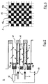
- FIG. 2 there is the heatable particle filter 2 from cup-shaped inlet channels 9, and arranged in parallel adjacent to the inlet channels 9 Outlet channels 10.
- the inlet channels 9 at the end with an inlet channel floor 11 provided; the outlet channels 10 are on the input side an outlet channel floor 12 closed.
- the particle-laden flow into the inlet channels 9 Exhaust gases 3 for filtering.
- the porous wall sections 13 settles on the part of the inlet channel 9 shows a particle layer 14 on the wall sections 13 from.
- Electric heating means 15a, 15b provided in the Outlet channels 10 in the area of the outlet channel bottom 12 are arranged.
- the electric heating means 15a, 15b with a pulse width modulated Supply voltage operated by a generator unit 16, starting from the voltage source 17 is generated.
- the electrical heating means 15 are designed in the manner of a coiled cantal wire and are based on the assigned outlet duct floor 12 arranged protruding into the outlet channel 10.
- the output from the electrical heating means 15 Heat radiation penetrates the wall sections 13 in Area of the associated outlet channel floors 12, heated the coating up to the activation temperature and triggers the burning of the in the adjacent inlet channels 9 located particle layer 14.
- outlet channels 10a each unheated outlet channels 10b.
- the unheated outlet channels 10b are opposite the heated outlet channels 10a not provided with an electrical heating means 15.
- the outlet channels 10 and 10 have the inlet channels 9 have a square cross-section, so that with the arrangement of the electrical heating means shown 15 only 25% of the outlet channels 10 with one Electric heating means 15 are to be provided to enable complete regeneration of the particle filter 2.
- the particulate filter 2 constructed in two parts and consists of an inlet side disk-shaped particle filter cover part 18, which has a contact side 20 which with a Particulate filter main part 19 comes into contact.
- the particle filter cover part 17 serves primarily for attachment or inclusion of the heating means 15.
- the heating means 15 are in this embodiment by gluing with a temperature resistant Adhesive with the particle filter cover part 18 connected. To in the attached state of the Heating means 15 a flat contact side 20 to the particle filter main part To form 19, the heating means 15 are within corresponding recesses on the contact side 20 of the particle filter cover part 18 inserted.
- the length of the outlet duct sections 10a of the particle filter cover part 18a is somewhat larger than the length of the heating elements 15a.
- the channel guide in the particle filter main part 19a compared to the particle filter cover part 18a by appropriately introduced Plug elements 21a are offset so as to be inexpensive To create flow guidance. Over the existing flow gap 22 the electrical wiring of the Heating elements 15a.
Abstract
Description
Die vorliegende Erfindung betrifft einen Partikelfilter zum Reinigen von motorischen Abgasen, mit topfförmig ausgebildeten Einlasskanälen, die endseitig mit einem Einlasskanalboden versehen sind und in welche partikelbeladene Abgase einströmen, sowie parallel benachbart zu den Einlasskanälen angeordnete und hierzu umgekehrt topfförmig ausgerichtete Auslasskanäle, welche je endseitig mit einem Auslasskanalboden versehen sind und welche die gereinigten Abgase ableiten, wobei sich durch die Filterung an den porösen, durchströmten Wandabschnitten seitens des Einlasskanals eine Partikelschicht absetzt, die zur Regeneration des Partikelfilters über elektrische Heizmittel abbrennbar ist.The present invention relates to a particle filter for cleaning engine exhaust, with cup-shaped trained inlet channels, the end with are provided with an inlet channel floor and into which particle-laden ones Exhaust gases flow in, as well as adjacent in parallel arranged to the inlet channels and vice versa pot-shaped outlet channels, each are provided at the end with an outlet channel floor and which derive the cleaned exhaust gases, whereby the filtering on the porous, flowed through wall sections deposits a particle layer from the inlet channel, the regeneration of the particle filter electrical heating means is burnable.
Partikelfilter dieser Art werden gewöhnlich dafür eingesetzt, den Partikelausstoß bei Abgasen von Verbrennungsmotoren - insbesondere von Dieselmotoren - zu reduzieren. Der technische Aufwand zur Erfüllung strenger Abgasnormen ist mit den gegenwärtigen Möglichkeiten erheblich. So macht eine vorgeschriebene Reduzierung des Partikelausstoßes um über 90 % die Ausrüstung von beispielsweise Dieselfahrzeugen mit Partikelfiltern unerlässlich und erfordert zudem aktive Maßnahmen zur Erstickung. Hierfür ist nach realistischen Schätzungen ein Kraftstoffmehrverbrauch von über 5% einzuplanen, weil die in den Abgasstrom erforderlicherweise einzuschaltende Filteranordnung einen erhöhten Energiebedarf verursachen. Der Energiebedarf steigt mit zunehmender Verrußung des Partikelfilters, das heißt mit anwachsender Partikelschicht. Die Partikelschicht ist jedoch durch Abbrennen beseitigbar, um den Partikelfilter insoweit wieder zu regenerieren.Particle filters of this type are commonly used for this used, the particle emission in exhaust gases from Internal combustion engines - especially diesel engines - too to reduce. The technical effort to meet stricter Emissions standards are significant with the current possibilities. So does a prescribed reduction in Particle emissions by over 90%, for example Diesel vehicles with particle filters are essential and also requires active measures for suffocation. This is based on realistic estimates Allow more fuel consumption of over 5% because the required to be switched on in the exhaust gas flow Filter arrangement cause an increased energy requirement. The energy requirement increases with increasing sootiness of the Particle filter, i.e. with an increasing particle layer. However, the particle layer is burned off can be removed in order to regenerate the particle filter again.
Ein gattungsgemäßer Partikelfilter ist aus der US 6,101,793 bekannt. Der aus einem porösen Keramikmaterial bestehende Partikelfilter weist langgestreckte topfförmig ausgebildete Einlasskanäle auf, in welche die vom Dieselmotor erzeugten partikelbeladenen Abgase einströmen. Parallel benachbart zu den Einlasskanälen sind Auslasskanäle angeordnet, welche die durch Filtern gereinigten Abgase an die Atmosphäre ableiten. Die Auslasskanäle sind ebenfalls topfförmig ausgebildet, jedoch umgekehrt zu den Einlasskanälen ausgerichtet. Bei dieser Anordnung erfolgt die Filterung bei Durchströmen der porösen gemeinsamen Wandabschnitte, wobei sich seitens des Einlasskanals eine Partikelschicht bildet. Die Einlasskanäle sowie die Auslasskanäle weisen hier einen quadratischen Querschnitt auf. Die Bodenbereiche der topfförmigen Kanäle sind durch diverse Stopfen gebildet, welche die Kanäle entsprechend ihrer vorstehend beschriebenen Ausrichtung an einem Ende verschließen.A generic particle filter is from the US 6,101,793 known. The one made of a porous ceramic material existing particle filter has elongated cup-shaped trained inlet channels into which the from Intake of particle-laden exhaust gases generated by the diesel engine. Outlet channels are parallel to the inlet channels arranged which the cleaned by filtering Discharge exhaust gases to the atmosphere. The outlet channels are also cup-shaped, but vice versa aligned with the inlet channels. With this arrangement the filtering takes place when the porous common flows through Wall sections, being on the part of the inlet duct forms a particle layer. The inlet channels as well the outlet channels here have a square Cross section on. The bottom areas of the pot-shaped channels are formed by various plugs, which are the channels according to their orientation described above close at one end.
Zur Regeneration des Partikelfilters weist dieser weiterhin elektrische Heizmittel auf, die filterausgangsseitig im Bereich der Öffnungen der Auslasskanäle angeordnet sind. Ein in der nachfolgenden Abgasleitung zwischen dem Partikelfilter und der Atmosphäre eingeschaltetes Gebläse wirkt zur Regeneration des Partikelfilters mit den elektrischen Heizmitteln zusammen. Das Gebläse wird bei Stillstand des Dieselmotors während einer definierten Zeitdauer eingeschaltet, so dass ein Luftstrom rückwärts über die aufgeheizten elektrischen Heizmittel strömt, wodurch sich der Luftstrom erhitzt, so dass ein Abbrennen der Partikelschicht einsetzt. Diese bekannte Lösung zur Regeneration des Partikelfilters weist jedoch den Nachteil auf, dass zur Erzeugung des aufgeheizten Luftstromes ein relativ hoher technischer Aufwand erforderlich ist.For the regeneration of the particle filter, this points continue to electrical heating means, the filter output side in the area of the openings of the outlet channels are arranged. One in the following exhaust pipe between the particle filter and the atmosphere Blower acts to regenerate the particle filter together with the electrical heating means. The Fan is stopped when the diesel engine is stopped defined period of time switched on, so that a Airflow backwards over the heated electrical Heating medium flows, which heats the air flow, so that the particle layer burns off. This Known solution for the regeneration of the particle filter has the disadvantage, however, that to generate the heated air flow a relatively high technical Effort is required.
Ein weiterer gattungsgemäßer Partikelfilter ist aus der US 5,782,941 bekannt, wobei hier zur Regeneration ein anderer technischer Weg beschritten wird. Der Partikelfilter ist aus einem äußeren rohrförmigen Filterteil aufgebaut, in welches ein inneres, kleineres rohrartiges Filterteil koaxial eingesetzt ist. Dieses zweite Filterteil ist auf der von den partikelbeladenen Abgasen angeströmten Seite verschlossen und bildet somit einen topfförmigen Auslasskanal. Der zwischen dem zweiten Filterteil und dem ersten Filterteil gebildete Bereich ist ebenfalls als ein topfförmiger Einlasskanal anzusehen. Hierin ist ein zylinderrohrartig geformtes und mit Durchbrüchen versehendes siebartiges Heizmittel angeordnet. Die hieran vorbeiströmenden partikelbeladenden Abgase transportieren bei einer Regeneration des Partikelfilters die vom elektrischen Heizmittel erzeugte Wärme an die Partikelschicht weiter, welche hierdurch abbrennt. Zwar ist das elektrische Heizmittel gemäß diesem Stand der Technik direkt in den Abgasstrom integriert, so dass keine zusätzlichen Mittel zur Erzeugung eines aufgeheizten Luftstromes erforderlich sind; gleichwohl erfordert der Betrieb des großflächigen zylinderförmig ausgebildeten Heizmittels ein recht hohen Energieaufwand.Another generic particle filter is known from US 5,782,941, here for regeneration another technical path is followed. The particle filter is made of an outer tubular filter part built, in which an inner, smaller tubular Filter part is used coaxially. This second filter part is on the flow of the exhaust gases laden with particles Side closed and thus forms a pot-shaped Outlet channel. The one between the second filter part and the area formed by the first filter part also to be regarded as a pot-shaped inlet duct. Herein is a cylinder tube-shaped and with openings provided sieve-like heating means. The particle-laden exhaust gases flowing past transport during regeneration of the particle filter the heat generated by the electrical heating medium to the Particle layer continues, which thereby burns. Though is the electrical heating medium according to this state of the Technology integrated directly into the exhaust gas flow, so that no additional means to generate a heated Airflow are required; nevertheless required the operation of the large-area cylindrical Heating means a very high amount of energy.
Es ist die Aufgabe der vorliegenden Erfindung einen Partikelfilter zum Reinigen von Abgasen eines Verbrennungsmotors zu schaffen, welcher auf einfache Weise energiesparend und mit hohem Wirkungsgrad regenerierbar ist.It is the object of the present invention a particle filter for cleaning exhaust gases To create internal combustion engine, which is simple In this way, energy-saving and regenerable with high efficiency is.
Die Aufgabe wird ausgehend von einem Partikelfilter gemäß dem Oberbegriff des Anspruchs 1 in Verbindung mit dessen kennzeichnenden Merkmalen gelöst. Die nachfolgenden abhängigen Ansprüche geben vorteilhafte Weiterbildungen der Erfindung wieder.The task is based on a particle filter in accordance with the preamble of claim 1 solved with its characteristic features. The the following dependent claims give advantageous Developments of the invention again.
Die Erfindung schließt die technische Lehre ein, die elektrischen Heizmittel eines Partikelfilters in zumindest einem Teil der Auslasskanäle derart im Bereich des Auslasskanalbodens anzuordnen, dass die von den elektrischen Heizmitteln abgegebene Wärmstrahlung ein Abbrennen der in den angrenzenden Einlasskanälen befindlichen Partikelschicht auslöst.The invention closes the technical teaching a, the electrical heating means of a particle filter in at least some of the outlet channels in the area of the outlet duct floor that the by the Heat emitted by electrical heating means burns off the one located in the adjacent inlet ducts Particle layer triggers.
Ein Vorteil der erfindungsgemäßen Anordnung der elektrischen Heizmittel liegt darin, dass hierdurch die Abgasströmung beim Eintritt in den Partikelfilter nicht gestört wird. Da sich die elektrischen Heizmittel in einem Bereich der Auslasskanäle befinden, der nicht im Bereich der Abgasströmung gelegen ist, wird die eingebrachte elektrische Energie zur Wärmeerzeugung deutlich besser genutzt. In Folge dessen kann die von den elektrischen Heizmitteln abgegebene Wärme hauptsächlich durch Wärmestrahlung auf die benachbarten Filterwände übertragen werden. Die Zündtemperatur für die Partikelschicht hängt ab von der Rußverteilung, insbesondere von der Schichtdicke und der Packungsdichte sowie der Rußqualität über die Filterlänge. Da mit der Abgasströmung die von den elektrischen Heizmitteln erzeugte Wärme weitertransportiert wird, erwärmen sich hierdurch die partikelschichtbehafteten Wandabschnitte, was die Regenerierung des Partikelfilters unterstützt. Durch die erfindungsgemäße Anordnung der elektrischen Heizmittel auf der Seite des gereinigten Abgases können zudem Korrosionsprozesse als Folge von Ruß- und Ascheablagerungen nachhaltig vermieden werden. Der erfindungsgemäß ausgebildete Partikelfilter ermöglicht eine selbsttragende Regeneration, auch unmittelbar nach einem Motorkaltstart bei Leerlaufbetrieb. Die elektrischen Heizmittel strahlen aufgrund ihrer hohen Oberflächentemperatur Wärme ab, die von den angrenzenden Wandabschnitten aufgenommen wird. Diese Wärmemenge startet die Regeneration auf der Einlassseite des Partikelfilters. Zu einem Teil wird die Wärme durch turbulente Strömungen in den Auslasskanälen an die dortigen Wandabschnitte abgegeben, wodurch eine Erwärmung erfolgt. Dadurch wird die von den elektrischen Heizmitteln erzeugte Wärme für die Regeneration besser genutzt und eine Unterbrechung des Rußabbrandes mit einer sehr hohen Wahrscheinlichkeit verhindert. Die sich selbst tragende Oxidation der Partikelschicht schreitet dann in Strömungsrichtung des Abgases bis zur Gasauslassseite fort und stellt damit den ursprünglichen Abgasgegendruck des Partikelfilters im unbeladenen Zustand, das heißt ohne Partikelschicht, wieder her.An advantage of the arrangement of the invention Electric heating means is that this Exhaust gas flow when entering the particle filter is not is disturbed. Because the electrical heating means in one Area of the exhaust ducts are not in the area the exhaust gas flow is located, the introduced electrical energy for heat generation clearly better used. As a result, the electrical Heat given off mainly by Transfer heat radiation to the neighboring filter walls become. The ignition temperature for the particle layer depends on the soot distribution, especially on the Layer thickness and the packing density as well as the soot quality about the filter length. Since with the exhaust gas flow the the heat generated by the electrical heating means is transported further As a result, the particle layers are heated Wall sections what regeneration of the particle filter supported. By the invention Arrangement of the electrical heating means on the side The cleaned exhaust gas can also cause corrosion processes avoided as a result of soot and ash deposits become. The particle filter designed according to the invention enables self-sustaining regeneration, too immediately after an engine cold start in idle mode. The electrical heating means radiate because of their high surface temperature heat from the adjacent Wall sections is added. This amount of heat regeneration starts on the inlet side of the Particulate filter. Some of the heat is turbulent Currents in the outlet channels to those there Wall sections released, whereby heating takes place. This will produce that generated by the electrical heating means Heat better used for regeneration and one Interruption of soot burning with a very high probability prevented. The self-supporting oxidation the particle layer then moves in the direction of flow of the exhaust gas up to the gas outlet side and thus represents the original exhaust back pressure of the particle filter in the unloaded state, i.e. without a particle layer, again.
Um die Gesamtzahl der benötigten elektrischen Heizmittel zu reduzieren, grenzen gemäß einer weiteren die Erfindung verbessernden Maßnahme an die mit elektrischen Heizmitteln ausgerüsteten Auslasskanäle jeweils unbeheizte - dass heißt ohne elektrische Heizmittel ausgerüstete Auslasskanäle - an. Um eine vollständige Regeneration des Partikelfilters zu erzielen, ist es nicht erforderlich, dass jeder Auslasskanal mit einem elektrischen Heizmittel ausgestattet ist. Bei einem quadratischen Kanalquerschnitt kann so die Anzahl der benötigten elektrischen Heizmittel auf 25 % der Anzahl der Auslasskanäle reduziert werden.To the total number of electrical required Reducing heating means limits according to another measure improving the invention to those with electrical Outlet channels equipped with heating means are each unheated - that means equipped without electrical heating means Exhaust channels - on. For a complete regeneration of the particle filter, it is not necessary that each outlet duct has an electrical Heating medium is equipped. With a square Channel cross section can thus the number of required electric heating medium to 25% of the number of outlet channels be reduced.
Vorzugsweise werden zur Einsparung elektrischer Energie die elektrischen Heizmittel mit einer pulsweitenmodulierten Versorgungsspannung betrieben. Diese pulsweitenmodulierte Versorgungsspannung braucht nur über eine kurze definierte Zeitdauer aufrecht erhalten werden, welche das Abbrennen der Partikelschicht startet. Nach dem über die elektrischen Heizmittel ausgelösten Start läuft der weitere Abbrennprozess wegen der exothermen Reaktion selbsttätig weiter. Durch die somit erzielte Minimierung des elektrischen Energiebedarfs wird das Bordnetz eines dieselmotorisch betriebenen Fahrzeuges minimal belastet.Preferably, to save electrical Energy the electrical heating means with a pulse width modulated Supply voltage operated. This pulse width modulated Supply voltage only needs one short defined period of time are maintained, which burning of the particle layer starts. After this Start triggered via the electrical heating means the further burning process due to the exothermic reaction automatically continue. Through the minimization thus achieved of the electrical energy requirement becomes the on-board electrical system vehicle powered by a diesel engine.
Um eine effektive Wärmeabstrahlung der elektrischen Heizmittel sicherzustellen, sind diese vorzugsweise nach Art eines gewendelten Kantal-Drahts ausgebildet. Die elektrischen Heizmittel sind vorteilhafter Weise zumindest teilweise in Serie zueinander geschalten. Somit führt ein Durchbrennen einzelner elektrischer Heizmittel nicht zum Ausfall des gesamten Partikelfilters. Einzelne Gruppen von in Serie zueinander geschalteten Heizmitteln ermöglichen eine sektorenweise Beheizung des Partikelfilters. To ensure effective heat radiation from the electrical To ensure heating means, these are preferred designed in the manner of a coiled cantal wire. The Electric heating means are advantageously at least partly connected in series. Consequently leads to the burning of individual electrical heating means not to the failure of the entire particle filter. Separate Groups of heating means connected in series enable the particle filter to be heated in sectors.
Die elektrischen Heizmittel sind vorzugsweise ausgehend vom zugeordneten Auslasskanalboden in den Auslasskanal hineinragend angeordnet, und zwar soweit, dass ein optimales Abstrahlen in die benachbarten Randbereiche der Einlasskanäle erzielt werden kann. Die elektrischen Heizmittel brauchen insoweit nicht sehr weit in den Auslasskanal hineinragen, um ihre erfindungsgemäße Funktion zu erfüllen.The electrical heating means are preferred starting from the assigned outlet duct floor into the outlet duct arranged protruding, to the extent that optimal blasting into the neighboring edge areas the inlet channels can be achieved. The electrical In this respect, heating agents do not need to go very far into the outlet duct protrude to their function according to the invention to fulfill.
Gemäß einer weiteren die Erfindung verbessernden Maßnahme ist der Partikelfilter zweiteilig aufgebaut. Dieser besteht aus einem scheibenförmigen auslasskanaibodenseitigen Partikelfilterdeckelteil, an dessen Kontaktseite zu einem Partikelfilterhauptteil die Heizmittel befestigt sind. Damit erfüllt das Partikelfilterdeckelteil zum Einen die Funktion eines Trägers für die elektrischen Heizmittel und dient zum Anderen auch zur Bildung der Auslasskanalböden.According to another which improves the invention Measure, the particle filter is made up of two parts. This consists of a disc-shaped outlet channel bottom Particulate filter cover part, on its contact side attached the heating medium to a particle filter main part are. The particle filter cover part thus fulfills on the one hand the function of a carrier for the electrical On the other hand also serves to form the Auslasskanalböden.
Beide Teile des Partikelfilters bestehen vorzugsweise aus demselben Filterwerkstoff und können durch Abtrennen erzeugt werden. Die Auslasskanalböden können durch entsprechend in das Partikelfilterdeckelteil eingebrachte Stöpselelemente ausgebildet werden. Die elektrischen Heizmittel sind am Partikelfilterdeckelteil vorzugsweise durch Kleben mit einem temperaturbeständigen Klebstoff angebracht. Alternativ hierzu ist es auch denkbar, die Heizmittel lösbar in die Auslasskanalböden des Partikelfilterdeckelteils einzustecken, was eine leichtere Austauschbarkeit im Reparaturfall gewährleistet. Die an der Kontaktseite des Partikelfilterdeckelteils befestigten Heizmittel liegen vorzugsweise in korrespondierenden Ausnehmungen, so dass bei montierten Heizmitteln eine insgesamt ebene Kontaktseite zum Partikelfilterhauptteil hin entsteht.Both parts of the particle filter are preferably made made of the same filter material and can Detachment are generated. The outlet duct floors can by correspondingly introduced into the particle filter cover part Plug elements are formed. The electrical Heating means are preferred on the particle filter cover part by gluing with a temperature resistant Adhesive attached. Alternatively, it is also conceivable the heating means releasably into the outlet channel floors of the Particulate filter cover part, which is an easier one Interchangeability guaranteed in case of repair. The attached to the contact side of the particle filter cover part Heating means are preferably in corresponding Recesses, so that a overall flat contact side to the particle filter main part there arises.
Gemäß einer weiteren Ausführungsform können die Heizmittel auch in Auslasskanalabschnitte des Partikelfilterdeckelteils in Richtung der Einlassseite hineinragend angeordnet und damit gänzlich seitens des entsprechend dickeren Partikelfilterdeckelteils platziert werden. Damit wird eine bessere Führung der Heizmittel erzielt. Die Heizmittel müssen nämlich nicht notwendigerweise in eine bestimmte Richtung entlang eines Auslasskanals angeordnet sein. Die Länge der Auslasskanalabschnitte des Partikelfilterdeckelteils sollte etwas größer sein als die Länge der Heizelemente selbst. Zwischen dem Partikelfilterdeckelteil und dem Partikelfilterhauptteil kann zudem ein Strömungsspalt beibehalten werden, wobei die Kanalführung im Partikelfilterhauptteil gegenüber dem Partikelfilterdeckelteil durch entsprechend eingebrachte Stöpselelemente versetzt erfolgen sollte, um eine günstige Strömungsführung zu schaffen. Über den bestehenden Strömungsspalt kann in vorteilhafter Weise die elektrische Verdrahtung der Heizelemente realisiert werden. Insoweit kann auf ein abgedichtetes Zusammenfügen beider Filterteile verzichtet werden.According to a further embodiment, the Heating medium also in the outlet duct sections of the particle filter cover part protruding towards the inlet side arranged and therefore entirely on the part of the thicker particle filter cover part. This leads to better management of the heating medium. The heating means do not necessarily have to in a certain direction along an outlet duct be arranged. The length of the outlet duct sections of the particle filter cover part should be slightly larger than the length of the heating elements themselves. Between the particulate filter cover part and the particulate filter body a flow gap can also be maintained, whereby the duct in the main part of the particle filter compared to the Particulate filter cover part by appropriately inserted Plug elements should be offset to be a cheap one To create flow guidance. Over the existing Flow gap can advantageously be the electrical Wiring of the heating elements can be realized. in this respect can be a sealed combination of both Filter parts can be dispensed with.
Der erfindungsgemäß ausgebildete Partikelfilter kann gemäß einer weiteren die Erfindung verbessernden Maßnahme im Rahmen einer Filteranordnung eingesetzt werden, bei welcher dem Partikelfilter direkt ein Stickoxid-Abscheidermodul nachgeschaltet ist. Das Stickoxid-Abscheidermodul kommt dabei direkt an der Gasauslassseite des Partikelfilters zur Anlage. Das Stickoxid-Abscheidermodul dient der Endstickung des Abgases, wobei auch eine Desulfatation vorteilhaft durchgeführt werden kann. Diese modulare Anordnung ermöglicht eine deutliche Einsparung an platinhaltigen Beschichtungsmaterialien.The particle filter designed according to the invention can according to another improve the invention Measure to be used as part of a filter arrangement, in which the particulate filter has a nitrogen oxide separator module is connected downstream. The nitrogen oxide separator module comes directly on the gas outlet side of the particle filter to the system. The nitrogen oxide separator module is used for the final embroidery of the exhaust gas, including one Desulfation can be carried out advantageously. This modular arrangement enables significant savings on platinum-containing coating materials.
Durch die direkte Nachschaltung eines Stickoxid-Abscheidermoduls an einen beheizten Partikelfilter kann die im Verlauf der Regeneration des Partikelfilters frei werdende exotherme Energie gleichzeitig auch zur Regeneration des nachgeschalteten Stickoxid-Abscheiders verwendet werden, wodurch sich der Wirkungsgrad der gesamten Filteranordnung deutlich verbessert. Durch diesen simultanen Regenerierungsprozess von Partikelfilter und Stickoxid-Abscheider wird darüber hinaus auch der steuerungstechnische Aufwand deutlich verringert. Die den beheizten Partikelfilter verlassenden gereinigten Abgase weisen eine Temperatur von bis zu 700 C° auf. Mit der Abgasströmung wird diese Wärme zum Stickoxid-Abscheidermodul weitertransportiert und leitet dort eine Regeneration in Form einer Desulfatation ein. Mit der Desulfatation werden Sulfatablagerungen im Stickoxid - Abscheidermodul beseitigt, die auf ein relativ hohen Schwefelgehalt des Dieselkraftstoffes und schwefelhaltige Bestandteile des Öls zurückzuführen sind.Through the direct connection of a nitrogen oxide separator module to a heated particle filter can in the course of regeneration of the particle filter released exothermic energy also for regeneration of the downstream nitrogen oxide separator be used, which increases the efficiency of the whole Filter arrangement significantly improved. Through this simultaneous regeneration process of particle filter and Nitrogen oxide separators also become the control technology Effort significantly reduced. The heated one Particulate filter leaving cleaned exhaust gases have a temperature of up to 700 ° C. With the exhaust gas flow this heat becomes a nitrogen oxide separator module transported and leads a regeneration there in the form of a desulfation ion. With the desulfation become sulfate deposits in the nitrogen oxide separator module eliminated, which is due to a relatively high sulfur content of the Diesel fuel and sulfurous components of the Oil.
Der vorstehend beschriebenen Filteranordnung kann ein weiterer Partikelfilter nachgeschaltet werden, dem wiederum ein weiteres Stickoxid-Abscheidermodul folgen kann. Dieser weitere Partikelfilter ist vorzugsweise unbeheizt und mit einer katalytischen Beschichtung versehen. Die mehrfache Anordnung erhöht den Wirkungsgrad der Filterung erheblich. Der modulare Aufbau der Filteranordnung bietet auch erhebliche energetische Vorteile. So ist durch die kompakte Bauweise eine Wärmeintegration zur Senkung des Energiebedarfs möglich und gleichzeitig können die bei der Regeneration unbeschichteter Partikelfilter entstehenden Gaskomponenten CO und HC unmittelbar zur Regeneration des nachfolgenden Stickoxid-Abscheidermoduls eingesetzt und damit abgebaut werden.The filter arrangement described above another particle filter can be added which in turn is followed by another nitrogen oxide separator module can. This further particle filter is preferred unheated and provided with a catalytic coating. The multiple arrangement increases the efficiency of the Filtering significantly. The modular structure of the filter arrangement also offers significant energetic benefits. So is due to the compact design, heat integration for Reduction of energy requirements possible and at the same time can the regeneration of uncoated particle filters emerging gas components CO and HC immediately for Regeneration of the subsequent nitrogen oxide separator module used and thus dismantled.
Weitere die Erfindung verbessernde Maßnahmen werden nachstehend gemeinsam mit der Beschreibung eines bevorzugten Ausführungsbeispiels der Erfindung anhand der Figuren näher dargestellt. Es zeigt:
- Fig. 1
- eine schematische Darstellung einer aus Partikelfiltern und Stickoxid-Abscheidermodulen bestehende Filteranordnung,
- Fig. 2
- eine Prinzipdarstellung der Funktionsweise eines erfindungsgemäß ausgebildeten Partikelfilters,
- Fig. 3
- eine schematische Draufsicht auf die eingangsseitige Stirnfläche des Partikelfilters,
- Fig. 4
- eine schematische Seitenansicht eines geteilt aufgebauten Partikelfilters mit hieran angebrachten elektrischen Heizmitteln.
- Fig. 5
- eine schematische Seitenansicht eines geteilt aufgebauten Partikelfilters mit hieran angebrachten elektrischen Heizmitteln in einer anderen Ausführungsform.
- Fig. 1
- 1 shows a schematic representation of a filter arrangement consisting of particle filters and nitrogen oxide separator modules,
- Fig. 2
- 2 shows a basic illustration of the functioning of a particle filter designed according to the invention,
- Fig. 3
- 2 shows a schematic top view of the end face of the particle filter on the input side,
- Fig. 4
- is a schematic side view of a divided particle filter with attached electrical heating means.
- Fig. 5
- is a schematic side view of a divided particle filter with attached electrical heating means in another embodiment.
Eine gemäß Fig. 1 aufgebaute Partikelfilteranordnung
zum Reinigen von Abgasen eines Dieselmotors umfasst
einen in einem Gehäuse langeordneten beheizten Partikelfilter
2. Eingangsseitig in den Partikelfilter 2 gelangen
partikelbeladene Abgase 3, welche beim Betrieb eines
- hier weiter nicht dargestellten - Dieselmotors entstehen.A particle filter arrangement constructed according to FIG. 1
for cleaning exhaust gases from a diesel engine
a long-order heated particle filter in a
Der Partikelfilter 2 ist mit elektrischen Heizmitteln
4 zur Regeneration ausgestattet, welche an nachstehender
Stelle eingehender beschrieben werden. Die den
beheizten Partikelfilter 2 verlassenden gereinigten Abgase
werden einem angrenzenden Stickoxid-Abscheidermodul
5 zugeführt. Das Stickoxid-Abscheidermodul 5 ist mit einem
geeigneten Katalysatormaterial versehen und dient der
Beseitigung von in den Abgasen enthaltenen schädlichen
Stickoxiden. Gemäß des dargestellten Ausführungsbeispiels
ist dem Stickoxid-Abscheidermodul 5 ein weiterer Partikelfilter
6 nachgeschaltet, der hier allerdings unbeheizt
ist. Die Regeneration dieses unbeheizten Partikelfilters
6 wird über die Heizmittel 4 des vorderen Partikelfilters
2 durch die Wärme aus der Partikeloxidation im Partikelfilters
2 mit übernommen. Die hierfür benötigte Wärme
wird über den Abgasstrom entsprechend weitergeleitet. Der
unbeheizte Partikelfilter 6 ist mit einer katalytischen
Beschichtung versehen. Entsprechend des hier dargestellten
modulartigen Aufbaus folgt dem unbeheizten Partikelfilter
6 schließlich wiederum ein weiteres Stickoxid-Abscheidermodul
7. Die über diese alternierende Filteranordnung
gereinigten Abgase 8 gelangen nach Verlassen des
Gehäuses 1 an die Atmosphäre. The
Gemäß Fig. 2 besteht der beheizbare Partikelfilter
2 aus topfförmig ausgebildeten Einlasskanälen 9,
sowie parallel benachbart zu den Einlasskanälen 9 angeordneten
Auslasskanäle 10. Zur Bildung der Topfform sind
die Einlasskanäle 9 endseitig mit einem Einlasskanalboden
11 versehen; die Auslasskanäle 10 sind eingangsseitig mit
einem Auslasskanalboden 12 verschlossen. Durch ihre Ausrichtung
strömen in die Einlasskanäle 9 die partikelbeladenen
Abgase 3 zur Filterung ein. Diese durchströmen die
porösen Wandabschnitte 13, welche durch die benachbarte
Anordnung der Einlasskanäle 9 zu den Auslasskanälen 10
gebildet werden, und gelangen durch die Auslasskanäle 10
hindurch als gereinigte Abgase 8 an die Atmosphäre. In
Folge der Filterung der partikelbeladenen Abgase 3 durch
die porösen Wandabschnitte 13 setzt sich seitens des Einlasskanals
9 eine Partikelschicht 14 an den Wandabschnitten
13 ab.According to FIG. 2, there is the
Zur Regeneration des Partikelfilters 2 sind
elektrische Heizmittel 15a, 15b vorgesehen, die in den
Auslasskanälen 10 im Bereich des Auslasskanalbodens 12
angeordnet sind.For the regeneration of the
Zur Einsparung elektrischer Energie werden die
elektrischen Heizmittel 15a, 15b mit einer pulsweitenmodulierten
Versorgungsspannung betrieben, welche durch
eine Generatoreinheit 16, ausgehend von der Spannungsquelle
17 erzeugt wird. Die elektrischen Heizmittel 15
sind nach Art eines gewendelten Kantal-Drahts ausgebildet
und sind ausgehend vom zugeordneten Auslasskanalboden 12
in den Auslasskanal 10 hineinragend angeordnet. To save electrical energy, the
electric heating means 15a, 15b with a pulse width modulated
Supply voltage operated by
a
Die von den elektrischen Heizmitteln 15 abgegebene
Wärmestrahlung durchdringt die Wandabschnitte 13 im
Bereich der zugeordneten Auslasskanalböden 12, erwärmt
die Beschichtung bis auf die Aktivierungstemperatur und
löst damit das Abbrennen der in den angrenzenden Einlasskanälen
9 befindlichen Partikelschicht 14 aus.The output from the electrical heating means 15
Heat radiation penetrates the
Durch die den Partikelfilter 2 durchströmenden
Abgase wird die Wärme entlang der Partikelschicht 14 in
Richtung der Einlasskanalböden 11 zum Abbrennen der gesamten
Partikelschicht 14 weitertransportiert, wobei das
Abbrennen nach dem Start selbsttätig erfolgt (exotherme
Reaktion).Through the flowing through the
Gemäß Fig. 3 grenzen an die mit elektrischen
Heizmitteln 15 ausgerüsteten Auslasskanäle 10a jeweils
unbeheizte Auslasskanäle 10b an. Die unbeheizten Auslasskanäle
10b sind gegenüber den beheizten Auslasskanälen
10a nicht mit einem elektrischen Heizmittel 15 versehen.
Wie hier dargestellt, besitzen die Auslasskanäle 10 sowie
die Einlasskanäle 9 einen quadratischen Querschnitt, so
dass bei der gezeigten Anordnung der elektrischen Heizmittel
15 lediglich 25 % der Auslasskanäle 10 mit einem
elektrischen Heizmittel 15 zu versehen sind, um eine
vollständige Regeneration des Partikelfilters 2 zu ermöglichen.3 border on with electrical
Heating means 15 equipped outlet channels 10a each
unheated outlet channels 10b. The unheated outlet channels
10b are opposite the heated outlet channels
10a not provided with an electrical heating means 15.
As shown here, the
Unter Bezugnahme auf Fig. 4 ist der Partikelfilter
2 zweiteilig aufgebaut und besteht aus einem einlassseitigen
scheibenförmigen Partikelfilterdeckelteil
18, das eine Kontaktseite 20 aufweist, welche mit einem
Partikelfilterhauptteil 19 in Kontakt tritt. Das Partikelfilterdeckelteil
17 dient vornehmlich der Befestigung
oder Aufnahme der Heizmittel 15. Die Heizmittel 15 sind
in diesem Ausführungsbeispiel durch Kleben mit einem temperaturbeständigen
Klebstoff mit dem Partikelfilterdeckelteil
18 verbunden. Um im befestigten Zustand der
Heizmittel 15 eine ebene Kontaktseite 20 zum Partikelfilterhauptteil
19 zu bilden, sind die Heizmittel 15 innerhalb
korrespondierender Ausnehmungen an der Kontaktseite
20 des Partikelfilterdeckelteils 18 eingelegt. Nach Zusammenfügen
des Partikelfilterdeckelteils 18 mit dem Partikelfilterhauptteil
19 entsteht der erfindungsgemäße beheizbare
Partikelfilter 2.Referring to Fig. 4, the
Gemäß der Ausführungsform nach Fig. 5 sind die
Heizmittel 15a in die einzelnen Auslasskanalabschnitte
10a des Partikelfilterdeckelteils 18a in Richtung der
Einlassseite hineinragend angeordnet und damit gänzlich
seitens des entsprechend dickeren Partikelfilterdeckelteils
18a platziert. Die Länge der Auslasskanalabschnitte
10a des Partikelfilterdeckelteils 18a ist etwas größer
als die Länge der Heizelemente 15a. Zwischen dem Partikelfilterdeckelteil
18a und dem Partikelfilterhauptteil
19a besteht zudem ein Strömungsspalt 22, wobei die Kanalführung
im Partikelfilterhauptteil 19a gegenüber dem Partikelfilterdeckelteil
18a durch entsprechend eingebrachte
Stöpselelemente 21a versetzt erfolgt, um eine günstige
Strömungsführung zu schaffen. Über den bestehenden Strömungsspalt
22 erfolgt die elektrische Verdrahtung der
Heizelemente 15a. 5 are the
Heating means 15a in the individual outlet channel sections
10a of the particle filter cover
- 11
- Gehäusecasing
- 22
- Partikelfilter, beheiztParticulate filter, heated
- 33
- Abgase, partikelbeladenExhaust gases, loaded with particles
- 44
- Heizmittelheating
- 55
- Stickoxid-AbscheidermodulNitrogen oxide separator module
- 66
- Partikelfilter, unbeheiztParticle filter, unheated
- 77
- Stickoxid-AbscheidermodulNitrogen oxide separator module
- 88th
- Abgase, gereinigtExhaust gases, cleaned
- 99
- Einlasskanalinlet channel
- 1010
- Auslasskanalexhaust port
- 1111
- EinlasskanalbodenInlet channel bottom
- 1212
- AuslasskanalbodenAuslasskanalboden
- 1313
- Wandabschnittwall section
- 1414
- Partikelschichtparticle layer
- 1515
- Heizmittelheating
- 1616
- Generatoreinheitgenerator unit
- 1717
- Spannungsquellevoltage source
- 1818
- PartikelfilterdeckelteilParticulate filter cover part
- 1919
- PartikelfilterhauptteilParticulate filter main part
- 2020
- KontaktseiteContact
- 2121
- Stöpselelementplug member
- 2222
- Strömungsspaltflow gap
Claims (13)
Applications Claiming Priority (2)
| Application Number | Priority Date | Filing Date | Title |
|---|---|---|---|
| DE10151425 | 2001-10-18 | ||
| DE10151425A DE10151425A1 (en) | 2001-10-18 | 2001-10-18 | Particle filter for cleaning engine exhaust gases |
Publications (2)
| Publication Number | Publication Date |
|---|---|
| EP1304455A1 true EP1304455A1 (en) | 2003-04-23 |
| EP1304455B1 EP1304455B1 (en) | 2009-09-30 |
Family
ID=7702906
Family Applications (1)
| Application Number | Title | Priority Date | Filing Date |
|---|---|---|---|
| EP02023261A Expired - Lifetime EP1304455B1 (en) | 2001-10-18 | 2002-10-17 | Particulate filter for purifying exhaust gases of internal combustion engines |
Country Status (3)
| Country | Link |
|---|---|
| EP (1) | EP1304455B1 (en) |
| AT (1) | ATE444437T1 (en) |
| DE (2) | DE10151425A1 (en) |
Cited By (4)
| Publication number | Priority date | Publication date | Assignee | Title |
|---|---|---|---|---|
| WO2004079170A1 (en) * | 2003-03-08 | 2004-09-16 | Johnson Matthey Public Limited Company | EXHAUST SYSTEM FOR LEAN BURN IC ENGINE INCLUDING PARTICULATE FILTER AND NOx ABSORBENT |
| EP1496212A1 (en) * | 2003-07-08 | 2005-01-12 | Toyota Jidosha Kabushiki Kaisha | Exhaust gas purification device for engine |
| EP1902202A1 (en) * | 2005-05-21 | 2008-03-26 | Umicore AG & Co. KG | Highly effective non-clogging filter unit |
| DE102016110527A1 (en) * | 2016-06-08 | 2017-12-14 | Dr. Ing. H.C. F. Porsche Aktiengesellschaft | Particle filter for an internal combustion engine |
Families Citing this family (5)
| Publication number | Priority date | Publication date | Assignee | Title |
|---|---|---|---|---|
| DE10308675A1 (en) * | 2003-02-28 | 2004-09-09 | Adam Opel Ag | Regenerable particle filter |
| US7469532B2 (en) * | 2005-09-22 | 2008-12-30 | Gm Global Technology Operations, Inc. | Diesel particulate filter (DPF) regeneration by electrical heating of resistive coatings |
| DE102006059966A1 (en) * | 2006-12-19 | 2008-06-26 | GM Global Technology Operations, Inc., Detroit | particulate Filter |
| US8146350B2 (en) | 2007-10-04 | 2012-04-03 | GM Global Technology Operations LLC | Variable power distribution for zoned regeneration of an electrically heated particulate filter |
| DE102008050019B4 (en) * | 2007-10-04 | 2020-07-09 | GM Global Technology Operations LLC (n. d. Ges. d. Staates Delaware) | System and method for variable power distribution for zone-wise regeneration of an electrically heated particle filter |
Citations (7)
| Publication number | Priority date | Publication date | Assignee | Title |
|---|---|---|---|---|
| US4512786A (en) * | 1982-04-21 | 1985-04-23 | Mazda Motor Corporation | Exhaust gas purifying device |
| US4519820A (en) * | 1982-08-05 | 1985-05-28 | Nippondenso Co., Ltd. | Fitter apparatus for purifying exhaust gases |
| US4872889A (en) * | 1987-04-11 | 1989-10-10 | Fev Motorentechnik Gmbh & Co., Kg | Filter system for the removal of engine emission particulates |
| JPH05163929A (en) * | 1991-12-12 | 1993-06-29 | Nippondenso Co Ltd | Exhaust particulate emission control device |
| EP0632189A1 (en) * | 1993-06-03 | 1995-01-04 | Kabushiki Kaisha Toyoda Jidoshokki Seisakusho | An exhaust gas purifier |
| US5782941A (en) | 1996-09-23 | 1998-07-21 | Sumitomo Electric Industries, Ltd. | Particulate trap for diesel engine |
| US6101793A (en) | 1997-04-22 | 2000-08-15 | Matsushita Electric Industrial Co., Ltd. | Exhaust gas filter, method of producing the same, and exhaust gas purification apparatus |
Family Cites Families (4)
| Publication number | Priority date | Publication date | Assignee | Title |
|---|---|---|---|---|
| DE3838589C1 (en) * | 1988-11-14 | 1989-12-28 | Voest-Alpine Automotive Ges.M.B.H., Linz, At | |
| JPH04179818A (en) * | 1990-11-14 | 1992-06-26 | Nippon Soken Inc | Exhaust gas fine particles purifing device |
| JPH10121941A (en) * | 1996-10-18 | 1998-05-12 | Sumitomo Electric Ind Ltd | Exhaust emission control device |
| FR2779177B1 (en) * | 1998-05-29 | 2000-06-30 | Renault | PARTICLE FILTER EXHAUST DEVICE |
-
2001
- 2001-10-18 DE DE10151425A patent/DE10151425A1/en not_active Withdrawn
-
2002
- 2002-10-17 EP EP02023261A patent/EP1304455B1/en not_active Expired - Lifetime
- 2002-10-17 DE DE50213879T patent/DE50213879D1/en not_active Expired - Lifetime
- 2002-10-17 AT AT02023261T patent/ATE444437T1/en not_active IP Right Cessation
Patent Citations (7)
| Publication number | Priority date | Publication date | Assignee | Title |
|---|---|---|---|---|
| US4512786A (en) * | 1982-04-21 | 1985-04-23 | Mazda Motor Corporation | Exhaust gas purifying device |
| US4519820A (en) * | 1982-08-05 | 1985-05-28 | Nippondenso Co., Ltd. | Fitter apparatus for purifying exhaust gases |
| US4872889A (en) * | 1987-04-11 | 1989-10-10 | Fev Motorentechnik Gmbh & Co., Kg | Filter system for the removal of engine emission particulates |
| JPH05163929A (en) * | 1991-12-12 | 1993-06-29 | Nippondenso Co Ltd | Exhaust particulate emission control device |
| EP0632189A1 (en) * | 1993-06-03 | 1995-01-04 | Kabushiki Kaisha Toyoda Jidoshokki Seisakusho | An exhaust gas purifier |
| US5782941A (en) | 1996-09-23 | 1998-07-21 | Sumitomo Electric Industries, Ltd. | Particulate trap for diesel engine |
| US6101793A (en) | 1997-04-22 | 2000-08-15 | Matsushita Electric Industrial Co., Ltd. | Exhaust gas filter, method of producing the same, and exhaust gas purification apparatus |
Cited By (7)
| Publication number | Priority date | Publication date | Assignee | Title |
|---|---|---|---|---|
| WO2004079170A1 (en) * | 2003-03-08 | 2004-09-16 | Johnson Matthey Public Limited Company | EXHAUST SYSTEM FOR LEAN BURN IC ENGINE INCLUDING PARTICULATE FILTER AND NOx ABSORBENT |
| US7930881B2 (en) | 2003-03-08 | 2011-04-26 | Johnson Matthey Public Limited Company | Exhaust system for lean burn IC engine including particulate filter and NOx absorbent |
| US8752367B2 (en) | 2003-03-08 | 2014-06-17 | Johnson Matthey PLLC | Exhaust system for lean burn IC engine including particulate filter and NOx absorbent |
| EP1496212A1 (en) * | 2003-07-08 | 2005-01-12 | Toyota Jidosha Kabushiki Kaisha | Exhaust gas purification device for engine |
| US7338642B2 (en) | 2003-07-08 | 2008-03-04 | Toyota Jidosha Kabushiki Kaisha | Exhaust gas purification device for engine |
| EP1902202A1 (en) * | 2005-05-21 | 2008-03-26 | Umicore AG & Co. KG | Highly effective non-clogging filter unit |
| DE102016110527A1 (en) * | 2016-06-08 | 2017-12-14 | Dr. Ing. H.C. F. Porsche Aktiengesellschaft | Particle filter for an internal combustion engine |
Also Published As
| Publication number | Publication date |
|---|---|
| DE10151425A1 (en) | 2003-04-30 |
| EP1304455B1 (en) | 2009-09-30 |
| DE50213879D1 (en) | 2009-11-12 |
| ATE444437T1 (en) | 2009-10-15 |
Similar Documents
| Publication | Publication Date | Title |
|---|---|---|
| DE3842282C2 (en) | Device for reducing the exhaust gas emission of a diesel engine | |
| EP0395840B1 (en) | Exhaust gas purifying soot filter for an internal combustion engine | |
| US6572682B2 (en) | Self-cleaning filter system using direct electrically heated sintered metal fiber filter media | |
| EP0238916B1 (en) | Process and device for the regeneration of exhaust filter systems | |
| DE60218082T2 (en) | Emission control system for a diesel internal combustion engine | |
| EP0630681B1 (en) | Process for the elimination of unwanted impurities from a gas | |
| DE102006044503A1 (en) | Regenerating a diesel particulate filter (DPF) by electrically heating resistive coatings | |
| DE102005025045A1 (en) | exhaust system | |
| WO2004051059A1 (en) | Motor vehicle provided with a diesel propulsion engine | |
| DE60101837T2 (en) | Exhaust particle filter for diesel engine | |
| EP1304455B1 (en) | Particulate filter for purifying exhaust gases of internal combustion engines | |
| DE102008030307A1 (en) | Catalyst arrangement for purifying exhaust gas flow of internal combustion engine in motor vehicle, has electrical heater for heating catalyst and/or exhaust gas flow, and another heater for heating another catalyst and/or exhaust gas flow | |
| DE60125204T2 (en) | METHOD AND DEVICE FOR TREATING A GAS STREAM | |
| DE10242303A1 (en) | Automotive diesel engine exhaust system has a soot particle filter module preceded by a NOx storage module | |
| WO2019170388A1 (en) | Method for operating a particulate filter in a vehicle, and particulate filter for an internal combustion engine in a vehicle | |
| WO1990012950A1 (en) | Diesel-soot filter with additional device for reducing oxides of nitrogen and/or oxidizing carbon monoxide | |
| DE102017222235A1 (en) | Method and device for heating an exhaust gas purification system of an internal combustion engine | |
| EP1399239B1 (en) | Particle filter operating by means of soot combustion and used for diesel engines | |
| DE102006041284B4 (en) | Method and device for the thermal regeneration of perfused particle filters | |
| EP3530339B1 (en) | Particle filter for a combustion engine and method for producing same | |
| DE10120973A1 (en) | Exhaust gas cleaning system with particle filter media and regeneration process for particle filter media | |
| EP1888887B1 (en) | Soot particle filter with catalytically coated heating elements | |
| DE102009014371A1 (en) | Motor exhaust gas filter, especially for diesel motors, has a leading oxidation filter with an integrated heater in front of the particle filter | |
| EP1026380B1 (en) | Combustion engine with a supply device for a combustion medium | |
| DE102005023580A1 (en) | Heat generator useful as an auxiliary heating unit for a vehicle comprises a particulate filter or oxidation catalyst mounted immediately downstream of a burner |
Legal Events
| Date | Code | Title | Description |
|---|---|---|---|
| PUAI | Public reference made under article 153(3) epc to a published international application that has entered the european phase |
Free format text: ORIGINAL CODE: 0009012 |
|
| AK | Designated contracting states |
Designated state(s): AT BE BG CH CY CZ DE DK EE ES FI FR GB GR IE IT LI LU MC NL PT SE SK TR |
|
| AX | Request for extension of the european patent |
Extension state: AL LT LV MK RO SI |
|
| 17P | Request for examination filed |
Effective date: 20031010 |
|
| AKX | Designation fees paid |
Designated state(s): AT BE BG CH CY CZ DE DK EE ES FI FR GB GR IE IT LI LU MC NL PT SE SK TR |
|
| 17Q | First examination report despatched |
Effective date: 20040121 |
|
| GRAP | Despatch of communication of intention to grant a patent |
Free format text: ORIGINAL CODE: EPIDOSNIGR1 |
|
| GRAS | Grant fee paid |
Free format text: ORIGINAL CODE: EPIDOSNIGR3 |
|
| GRAA | (expected) grant |
Free format text: ORIGINAL CODE: 0009210 |
|
| RAP1 | Party data changed (applicant data changed or rights of an application transferred) |
Owner name: GM GLOBAL TECHNOLOGY OPERATIONS, INC. |
|
| AK | Designated contracting states |
Kind code of ref document: B1 Designated state(s): AT BE BG CH CY CZ DE DK EE ES FI FR GB GR IE IT LI LU MC NL PT SE SK TR |
|
| REG | Reference to a national code |
Ref country code: GB Ref legal event code: FG4D Free format text: NOT ENGLISH Ref country code: CH Ref legal event code: EP |
|
| REG | Reference to a national code |
Ref country code: IE Ref legal event code: FG4D |
|
| REF | Corresponds to: |
Ref document number: 50213879 Country of ref document: DE Date of ref document: 20091112 Kind code of ref document: P |
|
| PG25 | Lapsed in a contracting state [announced via postgrant information from national office to epo] |
Ref country code: FI Free format text: LAPSE BECAUSE OF FAILURE TO SUBMIT A TRANSLATION OF THE DESCRIPTION OR TO PAY THE FEE WITHIN THE PRESCRIBED TIME-LIMIT Effective date: 20090930 Ref country code: SE Free format text: LAPSE BECAUSE OF FAILURE TO SUBMIT A TRANSLATION OF THE DESCRIPTION OR TO PAY THE FEE WITHIN THE PRESCRIBED TIME-LIMIT Effective date: 20090930 |
|
| NLV1 | Nl: lapsed or annulled due to failure to fulfill the requirements of art. 29p and 29m of the patents act | ||
| BERE | Be: lapsed |
Owner name: GM GLOBAL TECHNOLOGY OPERATIONS, INC. Effective date: 20091031 |
|
| PG25 | Lapsed in a contracting state [announced via postgrant information from national office to epo] |
Ref country code: PT Free format text: LAPSE BECAUSE OF FAILURE TO SUBMIT A TRANSLATION OF THE DESCRIPTION OR TO PAY THE FEE WITHIN THE PRESCRIBED TIME-LIMIT Effective date: 20100201 Ref country code: CZ Free format text: LAPSE BECAUSE OF FAILURE TO SUBMIT A TRANSLATION OF THE DESCRIPTION OR TO PAY THE FEE WITHIN THE PRESCRIBED TIME-LIMIT Effective date: 20090930 Ref country code: ES Free format text: LAPSE BECAUSE OF FAILURE TO SUBMIT A TRANSLATION OF THE DESCRIPTION OR TO PAY THE FEE WITHIN THE PRESCRIBED TIME-LIMIT Effective date: 20100110 Ref country code: EE Free format text: LAPSE BECAUSE OF FAILURE TO SUBMIT A TRANSLATION OF THE DESCRIPTION OR TO PAY THE FEE WITHIN THE PRESCRIBED TIME-LIMIT Effective date: 20090930 |
|
| REG | Reference to a national code |
Ref country code: IE Ref legal event code: FD4D |
|
| PG25 | Lapsed in a contracting state [announced via postgrant information from national office to epo] |
Ref country code: SK Free format text: LAPSE BECAUSE OF FAILURE TO SUBMIT A TRANSLATION OF THE DESCRIPTION OR TO PAY THE FEE WITHIN THE PRESCRIBED TIME-LIMIT Effective date: 20090930 Ref country code: CY Free format text: LAPSE BECAUSE OF FAILURE TO SUBMIT A TRANSLATION OF THE DESCRIPTION OR TO PAY THE FEE WITHIN THE PRESCRIBED TIME-LIMIT Effective date: 20090930 Ref country code: MC Free format text: LAPSE BECAUSE OF NON-PAYMENT OF DUE FEES Effective date: 20091031 |
|
| REG | Reference to a national code |
Ref country code: CH Ref legal event code: PL |
|
| PG25 | Lapsed in a contracting state [announced via postgrant information from national office to epo] |
Ref country code: IE Free format text: LAPSE BECAUSE OF FAILURE TO SUBMIT A TRANSLATION OF THE DESCRIPTION OR TO PAY THE FEE WITHIN THE PRESCRIBED TIME-LIMIT Effective date: 20090930 Ref country code: DK Free format text: LAPSE BECAUSE OF FAILURE TO SUBMIT A TRANSLATION OF THE DESCRIPTION OR TO PAY THE FEE WITHIN THE PRESCRIBED TIME-LIMIT Effective date: 20090930 Ref country code: NL Free format text: LAPSE BECAUSE OF FAILURE TO SUBMIT A TRANSLATION OF THE DESCRIPTION OR TO PAY THE FEE WITHIN THE PRESCRIBED TIME-LIMIT Effective date: 20090930 |
|
| PLBE | No opposition filed within time limit |
Free format text: ORIGINAL CODE: 0009261 |
|
| STAA | Information on the status of an ep patent application or granted ep patent |
Free format text: STATUS: NO OPPOSITION FILED WITHIN TIME LIMIT |
|
| 26N | No opposition filed |
Effective date: 20100701 |
|
| PG25 | Lapsed in a contracting state [announced via postgrant information from national office to epo] |
Ref country code: BE Free format text: LAPSE BECAUSE OF NON-PAYMENT OF DUE FEES Effective date: 20091031 Ref country code: GR Free format text: LAPSE BECAUSE OF FAILURE TO SUBMIT A TRANSLATION OF THE DESCRIPTION OR TO PAY THE FEE WITHIN THE PRESCRIBED TIME-LIMIT Effective date: 20091231 Ref country code: CH Free format text: LAPSE BECAUSE OF NON-PAYMENT OF DUE FEES Effective date: 20091031 Ref country code: LI Free format text: LAPSE BECAUSE OF NON-PAYMENT OF DUE FEES Effective date: 20091031 |
|
| PG25 | Lapsed in a contracting state [announced via postgrant information from national office to epo] |
Ref country code: AT Free format text: LAPSE BECAUSE OF NON-PAYMENT OF DUE FEES Effective date: 20091017 |
|
| PG25 | Lapsed in a contracting state [announced via postgrant information from national office to epo] |
Ref country code: IT Free format text: LAPSE BECAUSE OF FAILURE TO SUBMIT A TRANSLATION OF THE DESCRIPTION OR TO PAY THE FEE WITHIN THE PRESCRIBED TIME-LIMIT Effective date: 20090930 Ref country code: BG Free format text: LAPSE BECAUSE OF FAILURE TO SUBMIT A TRANSLATION OF THE DESCRIPTION OR TO PAY THE FEE WITHIN THE PRESCRIBED TIME-LIMIT Effective date: 20091031 |
|
| PG25 | Lapsed in a contracting state [announced via postgrant information from national office to epo] |
Ref country code: LU Free format text: LAPSE BECAUSE OF NON-PAYMENT OF DUE FEES Effective date: 20091017 |
|
| REG | Reference to a national code |
Ref country code: DE Ref legal event code: R081 Ref document number: 50213879 Country of ref document: DE Owner name: GM GLOBAL TECHNOLOGY OPERATIONS LLC (N. D. GES, US Free format text: FORMER OWNER: GM GLOBAL TECHNOLOGY OPERATIONS, INC., DETROIT, MICH., US Effective date: 20110323 |
|
| PG25 | Lapsed in a contracting state [announced via postgrant information from national office to epo] |
Ref country code: TR Free format text: LAPSE BECAUSE OF FAILURE TO SUBMIT A TRANSLATION OF THE DESCRIPTION OR TO PAY THE FEE WITHIN THE PRESCRIBED TIME-LIMIT Effective date: 20090930 |
|
| PGFP | Annual fee paid to national office [announced via postgrant information from national office to epo] |
Ref country code: FR Payment date: 20121018 Year of fee payment: 11 Ref country code: DE Payment date: 20121010 Year of fee payment: 11 |
|
| PGFP | Annual fee paid to national office [announced via postgrant information from national office to epo] |
Ref country code: GB Payment date: 20121017 Year of fee payment: 11 |
|
| GBPC | Gb: european patent ceased through non-payment of renewal fee |
Effective date: 20131017 |
|
| PG25 | Lapsed in a contracting state [announced via postgrant information from national office to epo] |
Ref country code: GB Free format text: LAPSE BECAUSE OF NON-PAYMENT OF DUE FEES Effective date: 20131017 |
|
| REG | Reference to a national code |
Ref country code: FR Ref legal event code: ST Effective date: 20140630 |
|
| REG | Reference to a national code |
Ref country code: DE Ref legal event code: R119 Ref document number: 50213879 Country of ref document: DE Effective date: 20140501 |
|
| PG25 | Lapsed in a contracting state [announced via postgrant information from national office to epo] |
Ref country code: FR Free format text: LAPSE BECAUSE OF NON-PAYMENT OF DUE FEES Effective date: 20131031 Ref country code: DE Free format text: LAPSE BECAUSE OF NON-PAYMENT OF DUE FEES Effective date: 20140501 |