EP1304308A1 - Truck mast - Google Patents
Truck mast Download PDFInfo
- Publication number
- EP1304308A1 EP1304308A1 EP02396154A EP02396154A EP1304308A1 EP 1304308 A1 EP1304308 A1 EP 1304308A1 EP 02396154 A EP02396154 A EP 02396154A EP 02396154 A EP02396154 A EP 02396154A EP 1304308 A1 EP1304308 A1 EP 1304308A1
- Authority
- EP
- European Patent Office
- Prior art keywords
- flange
- integrated structure
- mast
- truck
- centre
- Prior art date
- Legal status (The legal status is an assumption and is not a legal conclusion. Google has not performed a legal analysis and makes no representation as to the accuracy of the status listed.)
- Granted
Links
Images


Classifications
-
- B—PERFORMING OPERATIONS; TRANSPORTING
- B66—HOISTING; LIFTING; HAULING
- B66F—HOISTING, LIFTING, HAULING OR PUSHING, NOT OTHERWISE PROVIDED FOR, e.g. DEVICES WHICH APPLY A LIFTING OR PUSHING FORCE DIRECTLY TO THE SURFACE OF A LOAD
- B66F9/00—Devices for lifting or lowering bulky or heavy goods for loading or unloading purposes
- B66F9/06—Devices for lifting or lowering bulky or heavy goods for loading or unloading purposes movable, with their loads, on wheels or the like, e.g. fork-lift trucks
- B66F9/075—Constructional features or details
- B66F9/08—Masts; Guides; Chains
-
- B—PERFORMING OPERATIONS; TRANSPORTING
- B21—MECHANICAL METAL-WORKING WITHOUT ESSENTIALLY REMOVING MATERIAL; PUNCHING METAL
- B21C—MANUFACTURE OF METAL SHEETS, WIRE, RODS, TUBES, PROFILES OR LIKE SEMI-MANUFACTURED PRODUCTS OTHERWISE THAN BY ROLLING; AUXILIARY OPERATIONS USED IN CONNECTION WITH METAL-WORKING WITHOUT ESSENTIALLY REMOVING MATERIAL
- B21C23/00—Extruding metal; Impact extrusion
- B21C23/02—Making uncoated products
- B21C23/04—Making uncoated products by direct extrusion
- B21C23/14—Making other products
Definitions
- the invention relates to a truck mast. More specifically, the invention concerns a two- or multi-stage truck mast, which is either fixedly or tiltably mounted on a body and which comprises a first pair of substantially vertical beams, connected to each other with at least one substantially horizontal beam, said members providing a fixed mast assembly, the vicinity of said assembly being provided with at least one second pair of substantially co-directional vertical beams, which beams are connected to each other with at least one substantially horizontal beam and which members constitute a carrier adapted to move vertically relative to the fixed mast assembly under the propulsion of pistons in hydraulic cylinders, the drive and power being transmitted therefrom either directly or over chains or cables to the lift carrier, the substantially vertical beams and cylinder liners of said fixed mast assembly providing an integrated structure, wherein the cylinder liners are constituted by channels integrated inside the beams, as well as a method for manufacturing the integrated structure.
- mast truck refers to an industrial truck or forklift mobile on at least three wheels, comprising a mast structure which consists of a fixed mast assembly and a lift carrier. It may further include movable intermediate carriers for increasing the lifting height of a truck or forklift. Thus, there will be two or more stages to the truck.
- the truck mast connects in a fixed or articulated fashion to the body of a truck as designated in standard EN 1726-1 or EN 1726-2, e.g. fig. 1.
- stages or sections are movable relative to each other under the propulsion of pistons in hydraulic separate cylinders, from which the drive and power transmits either directly or over chains or cables to a load-lifting carrier.
- the mast and its stages constitute a telescopic guide system, wherein the stress is transmitted from the load-lifting carrier over guide rollers to the body structure of a truck.
- a mast truck is used, among others, for carrying containers, boxes or other such articles e.g. onto storage racks or vice versa.
- the mast and carriers of a truck are typically assembled by substantially vertically set sections, such as I-beams, which are connected to each other with crossmembers, and said mast and carriers being set in contact with each other to enable the same to travel vertically relative to each other through the intermediary of guide wheel bearings.
- the outermost intermediate carrier is movable through the intermediary of guide wheel bearings along the sections of a fixed mast assembly in vertical direction.
- the inner intermediate carriers are respectively movable relative to the outer intermediate carriers and the lift carrier relative to the innermost intermediate carrier. This results in a telescopic structure for lifting goods.
- the telescopic structure is typically operated by means of hydraulic cylinders.
- mast truck The intended use of a mast truck entails that the truck should provide as good a visibility as possible in every direction, but it is particularly important to have a field of vision as extensive and unobstructed as possible in the truck driving direction. Further requirements for the truck include a compact size and agility as operation often takes place in cramped storage facilities.
- the construction used in prior art mast trucks diminishes the driver's visual field in the most important observation direction because of a broad blind area created by a mast structure and lifting cylinders associated therewith.
- the hydraulic cylinders comprise a separate cylinder liner construction and a piston construction and are preferably mounted either alongside or behind the mast construction.
- a hot extrusible apertured profile is manufactured according to the following operations:
- the auxiliary tool shall bend and break in the final operation.
- the same problem is encountered in the process of manufacturing a beam by cold drawing. Due to this requirement introduced by the manufacturing method, the manufacture of beams as disclosed in DE 32 00 287 A1 would have to be performed by adding "counterweight" for placing the centre of mass at the centre of the cylinder hole or in the vicinity thereof. Consequently, the integral beam will be heavy, its production consuming a lot of steel and its external dimensions increasing. On the other hand, the dimensionally increased mast structure obstructs too much of the visual field or has a negative effect on agility of the machine.
- the discussed invention comprises a so-called integral beam for an integrated mast structure, wherein a beam and a cylinder liner are combined for one and the same beam, a bearing assembly for the mast structure, and an economically competitive manufacturing method for the mast structure.
- the driver's visual field in the most important observation direction increases substantially as the blind area diminishes because a cylinder liner is set within the mast structure.
- the mechanism becomes simpler, because it has fewer components, resulting in reduced maintenance and manufacturing costs.
- the manufacture of an integral beam of the invention in series production is economically viable. As physical outer dimensions, i.e. length and width, become smaller, the mast truck will be more agile to handle and easier to maneuver in cramped storage facilities.
- the inventive integral beam is also capable of providing a highly favourable rigidity/weight ratio.
- a bearing system for the beams can be provided in a simpler fashion.
- the inventive integral beam is preferably manufactured by hot extrusion or cold drawing of steel.
- the integral beam has its cylinder hole positioned at the centre of mass in the cross-section of the integral beam, or in the immediate vicinity thereof, most preferably at the precise centre of mass. A deviation from this causes immediately problems in hot extrusion or cold drawing and, depending on process parameters, disables the method completely at some point. Therefore, the solutions disclosed in DE 32 00 287 A1 are not implementable with the discussed manufacturing techniques.
- Fig. 1 illustrates one prior known variant for a mast truck.
- a mast truck body 1 is fitted with a mast assembly and hydraulic cylinder construction 2 for raising a left carrier 3.
- the lift carrier 3 comprises a forklift carrier. Raising of the lift carrier 3 is proceeds in two or more stages, depending on a mast assembly.
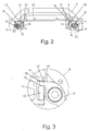
- Fig. 2 depicts a mast assembly for a mast truck of the invention in cross-section and in a plan view. It illustrates integrally designed, substantially vertical beams or uprights 4 and 5, which include built-in cylinder liners 29, along with pistons 6 and 7 therefor.
- the cylinder liners 29 are in the form of holes extending lengthwise through the integral beams 4 and 5, which are sealed, for example at the bottom thereof, with a pressure bushing or a plug and provided at the top thereof with packing boxes 8 for sealing and guiding the pistons 6 and 7.
- the beams 4 and 5 are connected to each other with a substantially horizontal cross-member 9.
- an intermediate carrier comprising substantially vertical I-sections 10 and 11 and a substantially crosswise member 12.
- the integral beams 4 and 5 are provided with a flange 13, said flange being fitted respectively between a flange 14 of the intermediate carrier's I-sections 10 and 11 and a bearing system 15 for operating the intermediate carrier in vertical direction.
- the flange 13 has its opposite surface provide a bearing surface 16 as well as a support surface 17.
- the integrally constructed beams 4 and 5 can be mounted on the body of a mast truck either fixedly or tiltably.
- Fig. 3 shows a detail A in fig. 2 in an enlarged view, wherein the bearing system 15 and the bracing 17 for a mast assembly is visualized more clearly.
- the I-section beam 11 has its bracing 17 arranged by the use of just one flange 13 of the integral beam 5.
- the bearing 15, which is preferably a rolling contact bearing, travels along the inner surface 16 of the flange 13 for operating the intermediate carrier and the flange's outer support surface 17 bears against a piece 18 fitted to the I-section's flange 14, which piece 18 is preferably a skrew or a like to optimize the clearance.
- Bracing of the I-section beam 11 is primarily effected by means of the bearing system 15 against the bearing surface 16 of the integral beam 5, and the bracing 17 present on the opposite side of the flange 13 only functions e.g. during a take-off, at which time the I-section beam momentarily leans in the opposite direction.
- the inner and outer surfaces 16 and 17 of the flange 13 are substantially parallel to the operating direction of a truck. The possible difference is due to a better operating performance of the truck.
- the outer surface 17 continues and turns around the cylinder liner 29 for 90 degrees.
- the support of the integrally constructed beams 4 and 5 is also possible to arrange in that curved area. Preferably it is arranged in straight surface 17 of the flange 13.
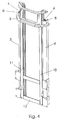
- Fig. 4 illustrates the mast assembly of fig. 2 obliquely from the front and above.
- the top of the beams 4 and 5 along the inner surface of the cylinder liners is preferably a machined area which is fitted, after manufacturing the sections, with separate packing boxes 8 for guiding the pistons 6 and 7.
- the packing boxes 8 are placed either at the top or at the bottom of the beams 4 and 5, whereby the pistons 6 and 7 are capable of moving either downward or upward, respectively.
- the cylinder liners are sealed with a pressure bushing or a plug. Consequently, the manufacturing tolerances for an integral beam can be slightly relaxed. Packing between the pistons 6 and 7 and the cylinder liner can also be implemented in some other, prior known fashion.
- An additional benefit is a simpler and lighter construction, which has an improved rigidity/weight ratio and which has fewer components. Fewer components result in lower manufacturing costs.
- the manufacture of a beam can be performed by exploiting some economically viable manufacturing technique, such as hot extrusion or cold drawing.
- Fig. 5 discloses a cross-section for the inventive integral beam 5.
- the integral beam 5 has its centre of mass located at the centre of a cylinder liner 29, whereby manufacturing of the beam is possible by hot extrusion or cold drawing.
- the integral beam or upright 5 includes the flange 13 and, for the purpose of locating the centre of mass, a flange 19.
- the mounting with bearings of the integral beam 5 is effected by bearing against the surface 16 and the bracing is effected by bearing against the surface 17.
- the structure has an elongated outline in the operating direction of a mast truck, giving the structure an excellent torsional rigidity, which is vital regarding operation of the mast assembly.
- Fig. 6 shows in cross-section another preferred embodiment for an integral beam 20 that can be manufactured by hot extrusion or cold drawing.
- the beam 20 has one 21 of its flanges turned 90 degrees counterclockwise with respect to the flange 19 of the beam 5 in figs. 2, 3, 4 and 5.
- the bearing system in this case is arranged the same way as with the beam 5 shown in the preceding figures in a one-sided manner along an outer surface 23 present in a flange 22 of the integral beam 20.
- Bracing is effected by way of an opposite surface 30 of the flange 22.
- the bracing can be arranged also on the curved surface of the beam 20 in the same way as with the beam 5 in figure 3.
- the characteristics achieved by this arrangement regarding torsional rigidity in the operating direction of a truck are not quite as excellent as those achieved with the beam 5 of fig. 5.
- the centre of mass is located, in compliance with the requirements of a manufacturing method, in the middle of a cylinder liner 29 of the integral beam 20.
- Fig. 7 illustrates yet another preferred cross-sectional embodiment for an integral beam 24 that can be manufactured by hot extrusion or cold drawing. It has been produced by combining a cylinder liner 29 with the middle portion of a member having a substantially rectangular cross-section, one end of which, a flange 25, can be provided with a bearing surface 26 and the other end of which constitutes a second flange 27.
- a flange 25 can be provided with a bearing surface 26 and the other end of which constitutes a second flange 27.
- the bearing system is only arranged in a one-sided manner along the surface 26 of the flange 25, and bracing is effected by way of an opposite surface 31 of the flange 25.
- an integral beam 5 having the cross-section shown in fig. 5 consumes appr. 27 kg/m of steel.
- the necessary additions to mass also increase the external dimensions of an integral beam, with the result that the beam again blocks a major part of the driver's visual field.
- the manufacturing e.g. by welding is not an economically competitive solution, either.
Landscapes
- Engineering & Computer Science (AREA)
- Mechanical Engineering (AREA)
- Transportation (AREA)
- Structural Engineering (AREA)
- Civil Engineering (AREA)
- Life Sciences & Earth Sciences (AREA)
- Geology (AREA)
- Forklifts And Lifting Vehicles (AREA)
Abstract
Description
- The invention relates to a truck mast. More specifically, the invention concerns a two- or multi-stage truck mast, which is either fixedly or tiltably mounted on a body and which comprises a first pair of substantially vertical beams, connected to each other with at least one substantially horizontal beam, said members providing a fixed mast assembly, the vicinity of said assembly being provided with at least one second pair of substantially co-directional vertical beams, which beams are connected to each other with at least one substantially horizontal beam and which members constitute a carrier adapted to move vertically relative to the fixed mast assembly under the propulsion of pistons in hydraulic cylinders, the drive and power being transmitted therefrom either directly or over chains or cables to the lift carrier, the substantially vertical beams and cylinder liners of said fixed mast assembly providing an integrated structure, wherein the cylinder liners are constituted by channels integrated inside the beams, as well as a method for manufacturing the integrated structure.
- The term mast truck refers to an industrial truck or forklift mobile on at least three wheels, comprising a mast structure which consists of a fixed mast assembly and a lift carrier. It may further include movable intermediate carriers for increasing the lifting height of a truck or forklift. Thus, there will be two or more stages to the truck. The truck mast connects in a fixed or articulated fashion to the body of a truck as designated in standard EN 1726-1 or EN 1726-2, e.g. fig. 1. In the mast, such stages or sections are movable relative to each other under the propulsion of pistons in hydraulic separate cylinders, from which the drive and power transmits either directly or over chains or cables to a load-lifting carrier. The mast and its stages constitute a telescopic guide system, wherein the stress is transmitted from the load-lifting carrier over guide rollers to the body structure of a truck. A mast truck is used, among others, for carrying containers, boxes or other such articles e.g. onto storage racks or vice versa.
- The mast and carriers of a truck are typically assembled by substantially vertically set sections, such as I-beams, which are connected to each other with crossmembers, and said mast and carriers being set in contact with each other to enable the same to travel vertically relative to each other through the intermediary of guide wheel bearings. The outermost intermediate carrier is movable through the intermediary of guide wheel bearings along the sections of a fixed mast assembly in vertical direction. The inner intermediate carriers are respectively movable relative to the outer intermediate carriers and the lift carrier relative to the innermost intermediate carrier. This results in a telescopic structure for lifting goods. The telescopic structure is typically operated by means of hydraulic cylinders.
- The intended use of a mast truck entails that the truck should provide as good a visibility as possible in every direction, but it is particularly important to have a field of vision as extensive and unobstructed as possible in the truck driving direction. Further requirements for the truck include a compact size and agility as operation often takes place in cramped storage facilities. The construction used in prior art mast trucks diminishes the driver's visual field in the most important observation direction because of a broad blind area created by a mast structure and lifting cylinders associated therewith. In these currently available mast trucks, the hydraulic cylinders comprise a separate cylinder liner construction and a piston construction and are preferably mounted either alongside or behind the mast construction.
- However, the publication DE 32 00 287 A1 discloses a prior known construction, wherein a U-section beam is integrally fitted with a tubular cylinder assembly. It is suggested that the tubular assembly be connected either to the end of a U-section or in the middle of the web on the side facing away from the legs. Manufacturing this prior known structure is nevertheless laborious and expensive.
- The solution disclosed in DE 32 00 287 A1 is implementable in practice, e.g. by welding a cylinder-forming tubular structure to a U-section beam. An integral structure manufactured this way will be expensive and the manufacturing requires a multitude of operations demanding accuracy and special skills. Other manufacturing techniques for producing an integral beam as set forth in the cited publication include e.g. casting or machining. However, none of the above manufacturing methods is an economically sound way of making an integral beam. Furthermore, if the cylinder structure is attached to the end of a U-section, the construction will be very long as viewed in the traveling direction of a truck, which in turn leads to poorer handling characteristics for the truck. The most preferred way of manufacturing an integral beam would be by hot extrusion or cold drawing.
- A hot extrusible apertured profile is manufactured according to the following operations:
- drilling the initial blank, having a diameter of e.g. 150 mm and a length of 600 mm, for a hole with a diameter of e.g. 50 mm
- heating the initial blank to red heat
- pushing an auxiliary tool through the hole in the initial blank (rod diameter 50 mm)
- pushing the initial blank, along with the auxiliary tool, through a profile form.
- If the hole is not in the centre of mass or in the immediate vicinity thereof, the auxiliary tool shall bend and break in the final operation. The same problem is encountered in the process of manufacturing a beam by cold drawing. Due to this requirement introduced by the manufacturing method, the manufacture of beams as disclosed in DE 32 00 287 A1 would have to be performed by adding "counterweight" for placing the centre of mass at the centre of the cylinder hole or in the vicinity thereof. Consequently, the integral beam will be heavy, its production consuming a lot of steel and its external dimensions increasing. On the other hand, the dimensionally increased mast structure obstructs too much of the visual field or has a negative effect on agility of the machine.
- It is an object of the invention to provide a manufacturing method for an integral beam, which is economically viable and which is capable of providing such a product that the blind area in the driver's visual field is small and the mast structure is light. The discussed invention comprises a so-called integral beam for an integrated mast structure, wherein a beam and a cylinder liner are combined for one and the same beam, a bearing assembly for the mast structure, and an economically competitive manufacturing method for the mast structure. The inventive solution is characterized by what is set forth in the annexed claims.
- The inventive solution provides advantages over prior art solutions as follows:
- The driver's visual field in the most important observation direction increases substantially as the blind area diminishes because a cylinder liner is set within the mast structure. The mechanism becomes simpler, because it has fewer components, resulting in reduced maintenance and manufacturing costs. The manufacture of an integral beam of the invention in series production is economically viable. As physical outer dimensions, i.e. length and width, become smaller, the mast truck will be more agile to handle and easier to maneuver in cramped storage facilities. The inventive integral beam is also capable of providing a highly favourable rigidity/weight ratio. In addition, a bearing system for the beams can be provided in a simpler fashion.
- The inventive integral beam is preferably manufactured by hot extrusion or cold drawing of steel. The integral beam has its cylinder hole positioned at the centre of mass in the cross-section of the integral beam, or in the immediate vicinity thereof, most preferably at the precise centre of mass. A deviation from this causes immediately problems in hot extrusion or cold drawing and, depending on process parameters, disables the method completely at some point. Therefore, the solutions disclosed in DE 32 00 287 A1 are not implementable with the discussed manufacturing techniques.
- The invention will now be described in more detail with reference to the accompanying drawings, in which
- fig. 1 shows a prior art mast truck in principle in a lateral 3-D view,
- fig. 2 shows from above a mast structure of the invention in cross-section, wherein cylinder liners are integrated with the mast structure,
- fig. 3 shows an enlarged view of a detail A in fig. 2, regarding a bearing system and bracing for the mast structure,
- fig. 4 shows the mast structure of fig. 2 illustrated at an angle from the front and above,
- fig. 5 shows an integral beam of the invention in cross-section, and
- figs. 6 and 7 show cross-sections for an integral beam of the invention in two other preferred embodiments.
-
- Fig. 1 illustrates one prior known variant for a mast truck. A
mast truck body 1 is fitted with a mast assembly andhydraulic cylinder construction 2 for raising aleft carrier 3. In this case, thelift carrier 3 comprises a forklift carrier. Raising of thelift carrier 3 is proceeds in two or more stages, depending on a mast assembly. - Fig. 2 depicts a mast assembly for a mast truck of the invention in cross-section and in a plan view. It illustrates integrally designed, substantially vertical beams or
uprights cylinder liners 29, along withpistons 6 and 7 therefor. Thecylinder liners 29 are in the form of holes extending lengthwise through theintegral beams packing boxes 8 for sealing and guiding thepistons 6 and 7. Thebeams horizontal cross-member 9. Inside the beams oruprights sections member 12. Theintegral beams flange 13, said flange being fitted respectively between aflange 14 of the intermediate carrier's I-sections bearing system 15 for operating the intermediate carrier in vertical direction. Theflange 13 has its opposite surface provide abearing surface 16 as well as asupport surface 17. The integrally constructedbeams - Fig. 3 shows a detail A in fig. 2 in an enlarged view, wherein the bearing
system 15 and the bracing 17 for a mast assembly is visualized more clearly. The I-section beam 11 has its bracing 17 arranged by the use of just oneflange 13 of theintegral beam 5. Thebearing 15, which is preferably a rolling contact bearing, travels along theinner surface 16 of theflange 13 for operating the intermediate carrier and the flange'souter support surface 17 bears against apiece 18 fitted to the I-section'sflange 14, whichpiece 18 is preferably a skrew or a like to optimize the clearance. Bracing of the I-section beam 11 is primarily effected by means of the bearingsystem 15 against the bearingsurface 16 of theintegral beam 5, and the bracing 17 present on the opposite side of theflange 13 only functions e.g. during a take-off, at which time the I-section beam momentarily leans in the opposite direction. The inner andouter surfaces flange 13 are substantially parallel to the operating direction of a truck. The possible difference is due to a better operating performance of the truck. Theouter surface 17 continues and turns around thecylinder liner 29 for 90 degrees. The support of the integrally constructedbeams straight surface 17 of theflange 13. - Fig. 4 illustrates the mast assembly of fig. 2 obliquely from the front and above. At the top of the
beams separate packing boxes 8 for guiding thepistons 6 and 7. Depending on a particular construction, thepacking boxes 8 are placed either at the top or at the bottom of thebeams pistons 6 and 7 are capable of moving either downward or upward, respectively. At the opposite ends thereof, the cylinder liners are sealed with a pressure bushing or a plug. Consequently, the manufacturing tolerances for an integral beam can be slightly relaxed. Packing between thepistons 6 and 7 and the cylinder liner can also be implemented in some other, prior known fashion. - The
integrated structures pistons 6 and 7, diminish the blind area in the driver's visual field and do not increase the length of a mast truck relative to its operating direction. An additional benefit is a simpler and lighter construction, which has an improved rigidity/weight ratio and which has fewer components. Fewer components result in lower manufacturing costs. Moreover, by virtue of the integral beam design, the manufacture of a beam can be performed by exploiting some economically viable manufacturing technique, such as hot extrusion or cold drawing. These above-mentioned manufacturing techniques require that the cross-sectional centre of mass of an integral beam be located at the centre of a cylinder liner, or in the immediate vicinity thereof. - Fig. 5 discloses a cross-section for the inventive
integral beam 5. Theintegral beam 5 has its centre of mass located at the centre of acylinder liner 29, whereby manufacturing of the beam is possible by hot extrusion or cold drawing. For the purpose of mounting with bearings and bracing, the integral beam orupright 5 includes theflange 13 and, for the purpose of locating the centre of mass, aflange 19. The mounting with bearings of theintegral beam 5 is effected by bearing against thesurface 16 and the bracing is effected by bearing against thesurface 17. The structure has an elongated outline in the operating direction of a mast truck, giving the structure an excellent torsional rigidity, which is vital regarding operation of the mast assembly. - Fig. 6 shows in cross-section another preferred embodiment for an
integral beam 20 that can be manufactured by hot extrusion or cold drawing. Thebeam 20 has one 21 of its flanges turned 90 degrees counterclockwise with respect to theflange 19 of thebeam 5 in figs. 2, 3, 4 and 5. Like above, the bearing system in this case is arranged the same way as with thebeam 5 shown in the preceding figures in a one-sided manner along anouter surface 23 present in aflange 22 of theintegral beam 20. Bracing is effected by way of anopposite surface 30 of theflange 22. The bracing can be arranged also on the curved surface of thebeam 20 in the same way as with thebeam 5 in figure 3. However, the characteristics achieved by this arrangement regarding torsional rigidity in the operating direction of a truck are not quite as excellent as those achieved with thebeam 5 of fig. 5. In this embodiment, as well, the centre of mass is located, in compliance with the requirements of a manufacturing method, in the middle of acylinder liner 29 of theintegral beam 20. - Fig. 7 illustrates yet another preferred cross-sectional embodiment for an
integral beam 24 that can be manufactured by hot extrusion or cold drawing. It has been produced by combining acylinder liner 29 with the middle portion of a member having a substantially rectangular cross-section, one end of which, aflange 25, can be provided with a bearingsurface 26 and the other end of which constitutes asecond flange 27. Thus, in order to locate the centre of mass in the middle of thecylinder liner 29, it is necessary to place more mass on a wall of the cylinder liner to provide aflange 28 on the opposite side relative to said rectangle. In this embodiment, as well, the bearing system is only arranged in a one-sided manner along thesurface 26 of theflange 25, and bracing is effected by way of anopposite surface 31 of theflange 25. - Manufacturing an
integral beam 5 having the cross-section shown in fig. 5 consumes appr. 27 kg/m of steel. The corresponding integral beams set forth in DE 32 00 287 A1, manufactured by hot extrusion, consume appr. 50 kg/m of steel. Since the price of steel beams per unit of length results directly from the amount of raw material used per unit of length, it is obvious that the solutions set forth in the cited publication are not economically viable when the manufacturing process is hot extrusion or cold drawing. In addition, the necessary additions to mass also increase the external dimensions of an integral beam, with the result that the beam again blocks a major part of the driver's visual field. As pointed out in the foregoing, the manufacturing e.g. by welding is not an economically competitive solution, either. - There are many possibilities of fitting a cylinder liner inside a section of the mast assembly. The figures only illustrate a few preferred compositions for integral beams that can be manufactured by hot extrusion or cold drawing. However, it is obvious for a person skilled in the art that a number of options exist for implementing the structure and that the scope of protection is more precisely defined by the following claims.
Claims (6)
- A two- or multi-stage truck mast, which is either fixedly or tiltably mounted on a body (1) and which comprises a first pair of substantially vertical beams (4, 5; 20; 24), connected to each other with at least one substantially horizontal beam (9), said members (4, 5, 9; 20; 24) providing a fixed mast assembly, the vicinity of said assembly being provided with at least one second pair of substantially co-directional vertical beams (10, 11), which beams (10, 11) are connected to each other with at least one substantially horizontal beam (12) and which members (10, 11, 12) constitute a carrier adapted to move vertically relative to the fixed mast assembly under the propulsion of pistons (6, 7) in hydraulic cylinders, the drive and power being transmitted therefrom either directly or over chains or cables to the lift carrier, the substantially vertical beams (4, 5; 20; 24) and cylinder liners (29) of said fixed mast assembly providing an integrated structure (4, 5; 20; 24), wherein the cylinder liners (29) are constituted by channels integrated inside the beams (4, 5; 20; 24), which integrated structure (4, 5; 20; 24) has its cross-sectional centre of mass located at the centre of the cylinder liner (29) or in the immediate vicinity thereof, such that the integrated structure (4, 5; 20; 24) is capable of being manufactured by hot extrusion or cold drawing, characterized in that the integrated structure (4, 5; 20; 24) is provided with a first flange (13; 22; 25), which comprises mainly parallel surfaces (16, 17; 23, 30; 26, 31) lying in a plane substantially transverse to the operating direction of the truck, the inner surface (16; 23; 26) of said first flange (13; 22; 25) being a bearing surface of a rolling contact bearing (15) and the outer surface (17; 30; 31) or the adjacent outer surface of the integrated structure (4, 5; 20) being a support surface, and with at least one second flange (19; 21; 27) for placing the centre of mass at the centre of the cylinder liner (29) or in the immediate vicinity thereof.
- A truck mast as set forth in claim 1, characterized in that the flanges (13, 19; 22, 21) are situated at opposite sides of the cylinder liner (29).
- A truck mast as set forth in claim 2, characterized in that the first flange (13) of the integrated structure (4, 5) being provided with the bearing surface (16) and the opposite support surface (17) and the second flange (19) form together a right angle.
- A truck mast as set forth in claim 2, characterized in that the first flange (22) of the integrated structure (20) being provided with the bearing surface (23) and the opposite support surface (30) and the second flange (21) are directed in opposite directions relative to each other.
- A truck mast as set forth in claim 2, characterized in that the first cross-sectional flange (25) of the integrated structure (24) being provided with the bearing surface (26) and the opposite support surface (31) and the second flange (27) are directed in opposite directions relative to each other and are situated on the same side of the cylinder liner (29), and that the wall of the cylinder liner (29) opposite with respect to the flanges (26, 27) is provided with more thickness in such a way that it constitutes a third flange (28).
- A method for manufacturing by hot extrusion or cold drawing an integrated structure (4, 5; 20; 24) for a truck mast as set forth in any of claims 1-5, characterized in that, in order to locate the centre of mass of the integrated structure (4, 5; 20; 24) in the middle of a cylinder liner (29) or in the immediate vicinity of the middle point, the integrated structure (4, 5; 20; 24) is formed with one flange (13; 22; 25), having an I-section beam (10, 11) bearing-mounted on its inner surface (16; 23; 26) with rolling contact bearing (15), its opposite outer surface (17; 30; 31) or the adjacent outer part of the integrated structure (4, 5; 20) adapted as a support surface, and with at least one second flange (19; 21; 27).
Applications Claiming Priority (2)
| Application Number | Priority Date | Filing Date | Title |
|---|---|---|---|
| FI20012031A FI111626B (en) | 2001-10-19 | 2001-10-19 | Forklift Mast |
| FI20012031 | 2001-10-19 |
Publications (2)
| Publication Number | Publication Date |
|---|---|
| EP1304308A1 true EP1304308A1 (en) | 2003-04-23 |
| EP1304308B1 EP1304308B1 (en) | 2006-06-21 |
Family
ID=8562086
Family Applications (1)
| Application Number | Title | Priority Date | Filing Date |
|---|---|---|---|
| EP02396154A Expired - Lifetime EP1304308B1 (en) | 2001-10-19 | 2002-10-10 | Truck mast |
Country Status (7)
| Country | Link |
|---|---|
| US (1) | US7121384B2 (en) |
| EP (1) | EP1304308B1 (en) |
| JP (1) | JP4094928B2 (en) |
| AT (1) | ATE330900T1 (en) |
| DE (1) | DE60212540T2 (en) |
| ES (1) | ES2266436T3 (en) |
| FI (1) | FI111626B (en) |
Cited By (3)
| Publication number | Priority date | Publication date | Assignee | Title |
|---|---|---|---|---|
| GB2387376B (en) * | 2002-04-10 | 2005-12-21 | Lansing Linde Ltd | Industrial trucks having lifting masts |
| WO2006003248A1 (en) * | 2004-07-06 | 2006-01-12 | Rocla Oyj | Forklift mast |
| EP1632452A3 (en) * | 2004-09-01 | 2006-04-26 | Jungheinrich Aktiengesellschaft | Industrial vehicle with cylinder rigidly connected to load moving device |
Families Citing this family (2)
| Publication number | Priority date | Publication date | Assignee | Title |
|---|---|---|---|---|
| LT6374B (en) | 2015-07-07 | 2017-03-27 | Kauno technologijos universitetas | METHOD OF SKIN DEATH |
| US12600609B2 (en) | 2024-06-20 | 2026-04-14 | Mitsubishi Logisnext Americas Inc. | Hose supports for facilitating the assembly of masts for material handling vehicles and related methods |
Citations (5)
| Publication number | Priority date | Publication date | Assignee | Title |
|---|---|---|---|---|
| US3362503A (en) * | 1966-02-24 | 1968-01-09 | Nautshno Izsledovatelski I Pk | Lifting means construction |
| EP0047137A1 (en) * | 1980-08-28 | 1982-03-10 | Coventry Climax Limited | Mast for industrial truck |
| DE3200287A1 (en) * | 1981-01-15 | 1982-09-23 | Institut za Elektrokari i Motokari, Sofija | LIFTING SYSTEM |
| GB2118140A (en) * | 1982-04-08 | 1983-10-26 | Barlow Handling Limited | Extending mast of fork lift truck |
| EP0283637A1 (en) * | 1987-03-13 | 1988-09-28 | ELECAR S.p.A. | Mast for fork lifts having the lifting cylinders located inside the lateral shapes |
Family Cites Families (10)
| Publication number | Priority date | Publication date | Assignee | Title |
|---|---|---|---|---|
| US4227717A (en) * | 1979-04-04 | 1980-10-14 | Bouvier Julien J | Motorcycle safety device |
| US4432438A (en) * | 1981-02-09 | 1984-02-21 | Clark Equipment Company | Upright for lift truck |
| US4458785A (en) * | 1982-10-25 | 1984-07-10 | Bushnell Jr Sherman W | Lift |
| JPS59217597A (en) * | 1983-05-23 | 1984-12-07 | 日産自動車株式会社 | Mast rail structure for forklift truck |
| JPS606598A (en) * | 1983-06-27 | 1985-01-14 | 小松フオ−クリフト株式会社 | Mast device |
| JPH0755794B2 (en) * | 1989-10-02 | 1995-06-14 | 日本輸送機株式会社 | Forklift mast equipment |
| DE4023170A1 (en) * | 1990-07-20 | 1992-01-23 | Linde Ag | Load lifting mechanism for fork-lift truck - has telescopic masts actuated by hydraulic cylinders |
| JPH10152300A (en) | 1996-11-22 | 1998-06-09 | Nissan Motor Co Ltd | Forklift truck mast device |
| JP3419265B2 (en) * | 1997-08-28 | 2003-06-23 | 日産自動車株式会社 | Mounting structure of lifting equipment lifting cylinder |
| US6505710B1 (en) * | 1997-10-14 | 2003-01-14 | Nissan Motor Co., Ltd. | Mast apparatus for fork lift trucks |
-
2001
- 2001-10-19 FI FI20012031A patent/FI111626B/en not_active IP Right Cessation
-
2002
- 2002-10-10 ES ES02396154T patent/ES2266436T3/en not_active Expired - Lifetime
- 2002-10-10 AT AT02396154T patent/ATE330900T1/en not_active IP Right Cessation
- 2002-10-10 DE DE60212540T patent/DE60212540T2/en not_active Expired - Lifetime
- 2002-10-10 EP EP02396154A patent/EP1304308B1/en not_active Expired - Lifetime
- 2002-10-17 US US10/273,937 patent/US7121384B2/en not_active Expired - Fee Related
- 2002-10-18 JP JP2002303687A patent/JP4094928B2/en not_active Expired - Lifetime
Patent Citations (5)
| Publication number | Priority date | Publication date | Assignee | Title |
|---|---|---|---|---|
| US3362503A (en) * | 1966-02-24 | 1968-01-09 | Nautshno Izsledovatelski I Pk | Lifting means construction |
| EP0047137A1 (en) * | 1980-08-28 | 1982-03-10 | Coventry Climax Limited | Mast for industrial truck |
| DE3200287A1 (en) * | 1981-01-15 | 1982-09-23 | Institut za Elektrokari i Motokari, Sofija | LIFTING SYSTEM |
| GB2118140A (en) * | 1982-04-08 | 1983-10-26 | Barlow Handling Limited | Extending mast of fork lift truck |
| EP0283637A1 (en) * | 1987-03-13 | 1988-09-28 | ELECAR S.p.A. | Mast for fork lifts having the lifting cylinders located inside the lateral shapes |
Cited By (3)
| Publication number | Priority date | Publication date | Assignee | Title |
|---|---|---|---|---|
| GB2387376B (en) * | 2002-04-10 | 2005-12-21 | Lansing Linde Ltd | Industrial trucks having lifting masts |
| WO2006003248A1 (en) * | 2004-07-06 | 2006-01-12 | Rocla Oyj | Forklift mast |
| EP1632452A3 (en) * | 2004-09-01 | 2006-04-26 | Jungheinrich Aktiengesellschaft | Industrial vehicle with cylinder rigidly connected to load moving device |
Also Published As
| Publication number | Publication date |
|---|---|
| DE60212540D1 (en) | 2006-08-03 |
| FI20012031A0 (en) | 2001-10-19 |
| JP2003176099A (en) | 2003-06-24 |
| FI20012031L (en) | 2003-04-20 |
| ES2266436T3 (en) | 2007-03-01 |
| DE60212540T2 (en) | 2007-06-06 |
| ATE330900T1 (en) | 2006-07-15 |
| US7121384B2 (en) | 2006-10-17 |
| EP1304308B1 (en) | 2006-06-21 |
| US20030089555A1 (en) | 2003-05-15 |
| FI111626B (en) | 2003-08-29 |
| JP4094928B2 (en) | 2008-06-04 |
Similar Documents
| Publication | Publication Date | Title |
|---|---|---|
| EP2030938B1 (en) | Stacker crane and weight reduction method for mast of the stacker crane | |
| US8714311B2 (en) | Monomast for a materials handling vehicle | |
| US10040675B2 (en) | Carriage assembly for materials handling vehicle and method for making same | |
| US20140219760A1 (en) | Reach assembly with offset pivot points for a materials handling vehicle | |
| EP1304308B1 (en) | Truck mast | |
| US6199665B1 (en) | Straddle arm for fork lift truck | |
| CN106185720A (en) | Large Copacity portable packed barium sulfate transporter | |
| JP5124270B2 (en) | Forklift mast | |
| KR100940051B1 (en) | Truck mast | |
| CN211032809U (en) | Cross beam structure for luxurious passenger liner sectional manufacturing and transporting assembly line trolley | |
| CN100396591C (en) | Truck mast | |
| EP1151959B1 (en) | Lift truck with extensible mast | |
| CN202297020U (en) | Working device of agricultural small-sized loading and unloading transport vehicle | |
| IT201900010098A1 (en) | ELECTRIC FORKLIFT | |
| CN215206715U (en) | Stacker travel drive device dismouting supporting seat | |
| RU2298521C2 (en) | Loader tower and method for manufacturing of integral construction | |
| CN201482980U (en) | Fully-suspended tundish car | |
| CN224147666U (en) | Cast beam type forklift mast | |
| CN220010925U (en) | Upright post structure and upright post stacker | |
| CN102514448A (en) | Axle case for turning drive vehicle axle | |
| CN201762065U (en) | Forklift door frame | |
| US8256578B2 (en) | Industrial truck with two wheel arms and method for assembling the industrial truck | |
| ITPD990081A1 (en) | TRANSMISSION FOR FORKLIFTS AND SIMILAR | |
| GB2387376A (en) | Lifting mast for an industrial truck | |
| JP2018100766A (en) | Conveyor cart with fluid pressure cylinder and lifting platform |
Legal Events
| Date | Code | Title | Description |
|---|---|---|---|
| PUAI | Public reference made under article 153(3) epc to a published international application that has entered the european phase |
Free format text: ORIGINAL CODE: 0009012 |
|
| AK | Designated contracting states |
Designated state(s): AT BE BG CH CY CZ DE DK EE ES FI FR GB GR IE IT LI LU MC NL PT SE SK TR |
|
| AX | Request for extension of the european patent |
Extension state: AL LT LV MK RO SI |
|
| 17P | Request for examination filed |
Effective date: 20031007 |
|
| AKX | Designation fees paid |
Designated state(s): AT BE BG CH CY CZ DE DK EE ES FI FR GB GR IE IT LI LU MC NL PT SE SK TR |
|
| 17Q | First examination report despatched |
Effective date: 20040113 |
|
| GRAP | Despatch of communication of intention to grant a patent |
Free format text: ORIGINAL CODE: EPIDOSNIGR1 |
|
| GRAS | Grant fee paid |
Free format text: ORIGINAL CODE: EPIDOSNIGR3 |
|
| GRAA | (expected) grant |
Free format text: ORIGINAL CODE: 0009210 |
|
| AK | Designated contracting states |
Kind code of ref document: B1 Designated state(s): AT BE BG CH CY CZ DE DK EE ES FI FR GB GR IE IT LI LU MC NL PT SE SK TR |
|
| PG25 | Lapsed in a contracting state [announced via postgrant information from national office to epo] |
Ref country code: IT Free format text: LAPSE BECAUSE OF FAILURE TO SUBMIT A TRANSLATION OF THE DESCRIPTION OR TO PAY THE FEE WITHIN THE PRESCRIBED TIME-LIMIT;WARNING: LAPSES OF ITALIAN PATENTS WITH EFFECTIVE DATE BEFORE 2007 MAY HAVE OCCURRED AT ANY TIME BEFORE 2007. THE CORRECT EFFECTIVE DATE MAY BE DIFFERENT FROM THE ONE RECORDED. Effective date: 20060621 Ref country code: AT Free format text: LAPSE BECAUSE OF FAILURE TO SUBMIT A TRANSLATION OF THE DESCRIPTION OR TO PAY THE FEE WITHIN THE PRESCRIBED TIME-LIMIT Effective date: 20060621 Ref country code: CH Free format text: LAPSE BECAUSE OF FAILURE TO SUBMIT A TRANSLATION OF THE DESCRIPTION OR TO PAY THE FEE WITHIN THE PRESCRIBED TIME-LIMIT Effective date: 20060621 Ref country code: BE Free format text: LAPSE BECAUSE OF FAILURE TO SUBMIT A TRANSLATION OF THE DESCRIPTION OR TO PAY THE FEE WITHIN THE PRESCRIBED TIME-LIMIT Effective date: 20060621 Ref country code: NL Free format text: LAPSE BECAUSE OF FAILURE TO SUBMIT A TRANSLATION OF THE DESCRIPTION OR TO PAY THE FEE WITHIN THE PRESCRIBED TIME-LIMIT Effective date: 20060621 Ref country code: LI Free format text: LAPSE BECAUSE OF FAILURE TO SUBMIT A TRANSLATION OF THE DESCRIPTION OR TO PAY THE FEE WITHIN THE PRESCRIBED TIME-LIMIT Effective date: 20060621 Ref country code: FI Free format text: LAPSE BECAUSE OF FAILURE TO SUBMIT A TRANSLATION OF THE DESCRIPTION OR TO PAY THE FEE WITHIN THE PRESCRIBED TIME-LIMIT Effective date: 20060621 |
|
| REG | Reference to a national code |
Ref country code: GB Ref legal event code: FG4D |
|
| REG | Reference to a national code |
Ref country code: CH Ref legal event code: EP |
|
| REG | Reference to a national code |
Ref country code: IE Ref legal event code: FG4D |
|
| REF | Corresponds to: |
Ref document number: 60212540 Country of ref document: DE Date of ref document: 20060803 Kind code of ref document: P |
|
| PG25 | Lapsed in a contracting state [announced via postgrant information from national office to epo] |
Ref country code: DK Free format text: LAPSE BECAUSE OF FAILURE TO SUBMIT A TRANSLATION OF THE DESCRIPTION OR TO PAY THE FEE WITHIN THE PRESCRIBED TIME-LIMIT Effective date: 20060921 |
|
| REG | Reference to a national code |
Ref country code: SE Ref legal event code: TRGR |
|
| PG25 | Lapsed in a contracting state [announced via postgrant information from national office to epo] |
Ref country code: IE Free format text: LAPSE BECAUSE OF NON-PAYMENT OF DUE FEES Effective date: 20061010 |
|
| PG25 | Lapsed in a contracting state [announced via postgrant information from national office to epo] |
Ref country code: MC Free format text: LAPSE BECAUSE OF NON-PAYMENT OF DUE FEES Effective date: 20061031 |
|
| PG25 | Lapsed in a contracting state [announced via postgrant information from national office to epo] |
Ref country code: PT Free format text: LAPSE BECAUSE OF FAILURE TO SUBMIT A TRANSLATION OF THE DESCRIPTION OR TO PAY THE FEE WITHIN THE PRESCRIBED TIME-LIMIT Effective date: 20061121 |
|
| NLV1 | Nl: lapsed or annulled due to failure to fulfill the requirements of art. 29p and 29m of the patents act | ||
| REG | Reference to a national code |
Ref country code: CH Ref legal event code: PL |
|
| ET | Fr: translation filed | ||
| REG | Reference to a national code |
Ref country code: ES Ref legal event code: FG2A Ref document number: 2266436 Country of ref document: ES Kind code of ref document: T3 |
|
| PLBE | No opposition filed within time limit |
Free format text: ORIGINAL CODE: 0009261 |
|
| STAA | Information on the status of an ep patent application or granted ep patent |
Free format text: STATUS: NO OPPOSITION FILED WITHIN TIME LIMIT |
|
| 26N | No opposition filed |
Effective date: 20070322 |
|
| PGFP | Annual fee paid to national office [announced via postgrant information from national office to epo] |
Ref country code: CZ Payment date: 20071008 Year of fee payment: 6 |
|
| PGFP | Annual fee paid to national office [announced via postgrant information from national office to epo] |
Ref country code: SK Payment date: 20071008 Year of fee payment: 6 |
|
| PG25 | Lapsed in a contracting state [announced via postgrant information from national office to epo] |
Ref country code: GR Free format text: LAPSE BECAUSE OF FAILURE TO SUBMIT A TRANSLATION OF THE DESCRIPTION OR TO PAY THE FEE WITHIN THE PRESCRIBED TIME-LIMIT Effective date: 20060922 |
|
| PG25 | Lapsed in a contracting state [announced via postgrant information from national office to epo] |
Ref country code: EE Free format text: LAPSE BECAUSE OF FAILURE TO SUBMIT A TRANSLATION OF THE DESCRIPTION OR TO PAY THE FEE WITHIN THE PRESCRIBED TIME-LIMIT Effective date: 20060621 Ref country code: BG Free format text: LAPSE BECAUSE OF FAILURE TO SUBMIT A TRANSLATION OF THE DESCRIPTION OR TO PAY THE FEE WITHIN THE PRESCRIBED TIME-LIMIT Effective date: 20060921 |
|
| PG25 | Lapsed in a contracting state [announced via postgrant information from national office to epo] |
Ref country code: LU Free format text: LAPSE BECAUSE OF NON-PAYMENT OF DUE FEES Effective date: 20061010 Ref country code: TR Free format text: LAPSE BECAUSE OF FAILURE TO SUBMIT A TRANSLATION OF THE DESCRIPTION OR TO PAY THE FEE WITHIN THE PRESCRIBED TIME-LIMIT Effective date: 20060621 |
|
| PG25 | Lapsed in a contracting state [announced via postgrant information from national office to epo] |
Ref country code: CY Free format text: LAPSE BECAUSE OF FAILURE TO SUBMIT A TRANSLATION OF THE DESCRIPTION OR TO PAY THE FEE WITHIN THE PRESCRIBED TIME-LIMIT Effective date: 20060621 |
|
| PG25 | Lapsed in a contracting state [announced via postgrant information from national office to epo] |
Ref country code: CZ Free format text: LAPSE BECAUSE OF NON-PAYMENT OF DUE FEES Effective date: 20081010 |
|
| PG25 | Lapsed in a contracting state [announced via postgrant information from national office to epo] |
Ref country code: SK Free format text: LAPSE BECAUSE OF NON-PAYMENT OF DUE FEES Effective date: 20081010 |
|
| REG | Reference to a national code |
Ref country code: FR Ref legal event code: PLFP Year of fee payment: 14 |
|
| PGFP | Annual fee paid to national office [announced via postgrant information from national office to epo] |
Ref country code: IT Payment date: 20151019 Year of fee payment: 14 |
|
| PGFP | Annual fee paid to national office [announced via postgrant information from national office to epo] |
Ref country code: SE Payment date: 20151022 Year of fee payment: 14 Ref country code: ES Payment date: 20151015 Year of fee payment: 14 |
|
| REG | Reference to a national code |
Ref country code: FR Ref legal event code: PLFP Year of fee payment: 15 |
|
| PG25 | Lapsed in a contracting state [announced via postgrant information from national office to epo] |
Ref country code: SE Free format text: LAPSE BECAUSE OF NON-PAYMENT OF DUE FEES Effective date: 20161011 |
|
| REG | Reference to a national code |
Ref country code: FR Ref legal event code: PLFP Year of fee payment: 16 |
|
| PG25 | Lapsed in a contracting state [announced via postgrant information from national office to epo] |
Ref country code: IT Free format text: LAPSE BECAUSE OF NON-PAYMENT OF DUE FEES Effective date: 20161010 |
|
| PGFP | Annual fee paid to national office [announced via postgrant information from national office to epo] |
Ref country code: DE Payment date: 20171017 Year of fee payment: 16 Ref country code: FR Payment date: 20171013 Year of fee payment: 16 |
|
| PGFP | Annual fee paid to national office [announced via postgrant information from national office to epo] |
Ref country code: GB Payment date: 20171011 Year of fee payment: 16 |
|
| PG25 | Lapsed in a contracting state [announced via postgrant information from national office to epo] |
Ref country code: ES Free format text: LAPSE BECAUSE OF FAILURE TO SUBMIT A TRANSLATION OF THE DESCRIPTION OR TO PAY THE FEE WITHIN THE PRESCRIBED TIME-LIMIT Effective date: 20060621 |
|
| REG | Reference to a national code |
Ref country code: ES Ref legal event code: FD2A Effective date: 20181122 |
|
| PG25 | Lapsed in a contracting state [announced via postgrant information from national office to epo] |
Ref country code: ES Free format text: LAPSE BECAUSE OF FAILURE TO SUBMIT A TRANSLATION OF THE DESCRIPTION OR TO PAY THE FEE WITHIN THE PRESCRIBED TIME-LIMIT Effective date: 20161011 |
|
| REG | Reference to a national code |
Ref country code: DE Ref legal event code: R119 Ref document number: 60212540 Country of ref document: DE |
|
| GBPC | Gb: european patent ceased through non-payment of renewal fee |
Effective date: 20181010 |
|
| PG25 | Lapsed in a contracting state [announced via postgrant information from national office to epo] |
Ref country code: DE Free format text: LAPSE BECAUSE OF NON-PAYMENT OF DUE FEES Effective date: 20190501 |
|
| PG25 | Lapsed in a contracting state [announced via postgrant information from national office to epo] |
Ref country code: FR Free format text: LAPSE BECAUSE OF NON-PAYMENT OF DUE FEES Effective date: 20181031 |
|
| PG25 | Lapsed in a contracting state [announced via postgrant information from national office to epo] |
Ref country code: GB Free format text: LAPSE BECAUSE OF NON-PAYMENT OF DUE FEES Effective date: 20181010 |