EP1304305A2 - Method and system for aligning moving sheets - Google Patents
Method and system for aligning moving sheets Download PDFInfo
- Publication number
- EP1304305A2 EP1304305A2 EP02023620A EP02023620A EP1304305A2 EP 1304305 A2 EP1304305 A2 EP 1304305A2 EP 02023620 A EP02023620 A EP 02023620A EP 02023620 A EP02023620 A EP 02023620A EP 1304305 A2 EP1304305 A2 EP 1304305A2
- Authority
- EP
- European Patent Office
- Prior art keywords
- sheets
- width
- cams
- sheet
- gate
- Prior art date
- Legal status (The legal status is an assumption and is not a legal conclusion. Google has not performed a legal analysis and makes no representation as to the accuracy of the status listed.)
- Granted
Links
- 238000000034 method Methods 0.000 title claims abstract description 15
- 230000007246 mechanism Effects 0.000 claims description 12
- 238000011144 upstream manufacturing Methods 0.000 claims description 6
- 238000013459 approach Methods 0.000 abstract description 2
- 230000001360 synchronised effect Effects 0.000 abstract description 2
- 238000003780 insertion Methods 0.000 description 3
- 230000037431 insertion Effects 0.000 description 3
- 230000008878 coupling Effects 0.000 description 1
- 238000010168 coupling process Methods 0.000 description 1
- 238000005859 coupling reaction Methods 0.000 description 1
- 238000000926 separation method Methods 0.000 description 1
- 230000001960 triggered effect Effects 0.000 description 1
Images




Classifications
-
- B—PERFORMING OPERATIONS; TRANSPORTING
- B43—WRITING OR DRAWING IMPLEMENTS; BUREAU ACCESSORIES
- B43M—BUREAU ACCESSORIES NOT OTHERWISE PROVIDED FOR
- B43M3/00—Devices for inserting documents into envelopes
- B43M3/04—Devices for inserting documents into envelopes automatic
-
- B—PERFORMING OPERATIONS; TRANSPORTING
- B41—PRINTING; LINING MACHINES; TYPEWRITERS; STAMPS
- B41J—TYPEWRITERS; SELECTIVE PRINTING MECHANISMS, i.e. MECHANISMS PRINTING OTHERWISE THAN FROM A FORME; CORRECTION OF TYPOGRAPHICAL ERRORS
- B41J11/00—Devices or arrangements of selective printing mechanisms, e.g. ink-jet printers or thermal printers, for supporting or handling copy material in sheet or web form
- B41J11/0045—Guides for printing material
- B41J11/0055—Lateral guides, e.g. guides for preventing skewed conveyance of printing material
-
- B—PERFORMING OPERATIONS; TRANSPORTING
- B65—CONVEYING; PACKING; STORING; HANDLING THIN OR FILAMENTARY MATERIAL
- B65H—HANDLING THIN OR FILAMENTARY MATERIAL, e.g. SHEETS, WEBS, CABLES
- B65H9/00—Registering, e.g. orientating, articles; Devices therefor
- B65H9/10—Pusher and like movable registers; Pusher or gripper devices which move articles into registered position
- B65H9/101—Pusher and like movable registers; Pusher or gripper devices which move articles into registered position acting on the edge of the article
-
- B—PERFORMING OPERATIONS; TRANSPORTING
- B65—CONVEYING; PACKING; STORING; HANDLING THIN OR FILAMENTARY MATERIAL
- B65H—HANDLING THIN OR FILAMENTARY MATERIAL, e.g. SHEETS, WEBS, CABLES
- B65H2301/00—Handling processes for sheets or webs
- B65H2301/30—Orientation, displacement, position of the handled material
- B65H2301/36—Positioning; Changing position
- B65H2301/361—Positioning; Changing position during displacement
- B65H2301/3611—Positioning; Changing position during displacement centering, positioning material symmetrically relatively to a given axis of displacement
-
- B—PERFORMING OPERATIONS; TRANSPORTING
- B65—CONVEYING; PACKING; STORING; HANDLING THIN OR FILAMENTARY MATERIAL
- B65H—HANDLING THIN OR FILAMENTARY MATERIAL, e.g. SHEETS, WEBS, CABLES
- B65H2301/00—Handling processes for sheets or webs
- B65H2301/40—Type of handling process
- B65H2301/44—Moving, forwarding, guiding material
- B65H2301/442—Moving, forwarding, guiding material by acting on edge of handled material
- B65H2301/4423—Moving, forwarding, guiding material by acting on edge of handled material with guide member rotating against the edges of material
-
- Y—GENERAL TAGGING OF NEW TECHNOLOGICAL DEVELOPMENTS; GENERAL TAGGING OF CROSS-SECTIONAL TECHNOLOGIES SPANNING OVER SEVERAL SECTIONS OF THE IPC; TECHNICAL SUBJECTS COVERED BY FORMER USPC CROSS-REFERENCE ART COLLECTIONS [XRACs] AND DIGESTS
- Y10—TECHNICAL SUBJECTS COVERED BY FORMER USPC
- Y10S—TECHNICAL SUBJECTS COVERED BY FORMER USPC CROSS-REFERENCE ART COLLECTIONS [XRACs] AND DIGESTS
- Y10S414/00—Material or article handling
- Y10S414/10—Associated with forming or dispersing groups of intersupporting articles, e.g. stacking patterns
- Y10S414/12—Associated with forming or dispersing groups of intersupporting articles, e.g. stacking patterns including means pressing against top or end of group
Definitions
- the present invention relates to an envelope inserting machine and, more particularly, to a method and device for aligning enclosure materials, which are released from enclosure feeders and collated into a stack to be inserted into an envelope for mailing.
- the gathering section In an inserting machine for mass mailing, there is a gathering section where enclosure material is gathered before it is inserted into an envelope at an envelope insertion area.
- the gathering section is sometimes referred to as a chassis subsystem, which includes a gathering transport with pusher fingers rigidly attached to a conveyor belt and a plurality of enclosure feeders mounted above the transport. If the enclosure material contains many documents, these documents must be separately fed from different enclosure feeders.
- U.S. Patent No. 4,501,417 discloses an inserter feeder assembly for feeding enclosures
- U.S. Patent No, 4,753,429 discloses a collating station
- U.S. Patent No, 5,660,030 discloses an envelope inserter station wherein envelopes are separately provided to an envelope supporting deck where envelopes are spread open so as to allow enclosure materials to be stuffed into the envelopes.
- an inserting machine 10 typically includes a gathering section 12 an envelope feeder/inserter station 14.
- the gathering section 12 includes a plurality of enclosure feeders 20 for separately releasing documents 100.
- the released documents are pushed toward the envelope feeder/inserter station 14 by a plurality of pusher fingers 30, which are attached to an endless chain 32 for movement.
- the document 100 released by a respective enclosure feeder 20 lands on a tray 24 and then pushed off the tray 24 by an approaching pusher finger 30 onto a deck 40. As the pusher fingers 30 move forward, they collect more released documents 100.
- the envelope feeder/inserter station 14 includes an envelope feeder 22 positioned above an envelope insertion area 16 for releasing one envelope 200 at a time so that the stack 110 can be inserted in the released envelope 200 (see Figure 2).
- the enclosure feeders 20 are arranged and aligned such that the released documents 100 are supposed to line up with each other when are collated into a stack 110 .
- a document 100 is released onto the tray 24, as shown in Figure 2, it may not land at a designated position.
- the object can be achieved by providing a pair of alignment devices positioned at opposite side of the moving stack to push the side edges of the sheets toward a center line of the deck of a gathering section in an inserting machine.
- the first aspect of the present invention is an alignment system for aligning a stack having a stack width and containing a plurality of sheets, each sheet having a leading edge and two opposing side edges defining a sheet width smaller than the stack width, wherein the stack is moved along a path in a moving direction toward a downstream end.
- the alignment system comprising; a pair of alignment devices located at opposite sides of a center line of the path near the downstream end for pushing the opposing side edges of the sheets toward the center line, wherein each alignment device comprises a cam having an outer surface with at least one section thereof having a non-constant radius, and wherein the outer surfaces face each other to define a gate having a gate width, and a mechanism to cause the cams to rotate synchronously with respect to each other in opposite directions to change the gate width such that the gate width is greater than the stack width when the leading edge of the sheets moves into the gate, and the gate width is reduced after the leading edge has passed the gate until the gate width is substantially equal to the sheet width so as to cause the side edges of the sheets in the stack to be aligned with each other.
- each of the cams is mounted on a shaft
- the alignment system further comprises a mechanism to relocate the shafts relative to each other to adjust the gate width according to the sheet width.
- the outer surface of the cams is spiral in shape. It is also possible that the outer surface of the cams is circular in shape and each cam is rotated about an off-centered axis. It is also possible that each of the cams comprises a first circular disk rotatably mounted on a second circular disk and the cam is caused to rotate about the center of the second circular disk, wherein the outer surface of the cams is the circumference of the first circular disk. Alternatively, each cam is caused to rotate about a rotational axis and the outer surface of each cam comprises two spiral surface sections symmetrically arranged about the rotational axis.
- the sheets are moved at a constant sheet velocity by a moving means, and the cams are operatively linked to the moving means for rotation in synchronism with the movement of the sheets. It is also preferred that the cams are rotated at a constant angular velocity defining a tangential velocity at a point on the outer surface and the tangential velocity is substantially equal to the sheet velocity when the gate width is substantially equal to the sheet width.
- the sheets are moved at a constant sheet velocity by a moving means and the cams are operatively linked to the moving means for rotation in synchronism with the movement of the sheets, and wherein the cams are rotated in a constant angular velocity.
- a sheet collation apparatus having an upstream end and a downstream end, the sheet collation apparatus comprises:
- Figure 1 is a diagrammatic representation illustrating a prior art inserting machine.
- Figure 2 is a diagrammatic representation illustrating part of the prior art inserting machine as shown in Figure 1.
- Figure 3 is a diagrammatic representation illustrating the location of the alignment system, according to the present invention, in relation to envelope feeder/inserter station in an inserting machine.
- Figure 4 is a diagrammatic representation illustrating the alignment system, according to the present invention.
- Figure 5a is a diagrammatic representation illustrating the alignment system, when the leading edge of a stack of sheets is moved into the aligning position of the alignment system.
- Figure 5b is a diagrammatic representation illustrating the alignment system, according to the present invention, when the stack is about halfway through the aligning position of the alignment system.
- Figure 5c is a diagrammatic representation illustrating the alignment system, according to the present invention, when the stack is almost moved through the aligning position of the alignment system.
- Figure 5d is a diagrammatic representation illustrating the alignment system, according to the present invention, when the trailing edge of the stack has reached the aligning position of the alignment system.
- Figure 5e is a diagrammatic representation illustrating the alignment system, according to the present invention, when the stack is completely off the alignment system and a following stack is approaching the aligning position.
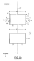
- Figure 6a is a diagrammatic representation illustrating the alignment system having an adjusting mechanism to accommodate the width of sheets.
- Figure 6b is a diagrammatic representation illustrating the alignment system being used to align a stack of sheets with a greater width.
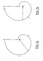
- Figure 7a is a diagrammatic representation illustrating the preferred embodiment of the cam used in the alignment system, according to the present invention.
- Figure 7b is a diagrammatic representation illustrating a variation of the cam used in the alignment system, according to the present invention.
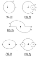
- Figure 7c is a diagrammatic representation illustrating another embodiment of the cam used in the alignment system, according to the present invention.
- Figure 7d is a diagrammatic representation illustrating yet another embodiment of the cam used in the alignment system, according to the present invention.
- Figure 7e is a diagrammatic representation illustrating still another embodiment of the cam used in the alignment system, according to the present invention.
- Figure 7f is a diagrammatic representation illustrating a further embodiment of the cam used in the alignment system, according to the present invention.
- Figure 7g is a diagrammatic representation illustrating yet another embodiment of the cam used in the alignment system, according to the present invention.
- FIG. 3 shows the location of the alignment system in relation to the sheet collation section 12 in an inserting machine 10 .
- the alignment system according to the present invention is denoted by reference numeral 50 .
- the alignment system 50 is located in the downstream end.
- the alignment system 50 is linked to the endless chain 32 with coupling mechanism 60, 62 so that the alignment system 50 is caused to operate in synchronism with the pusher fingers 30.
- FIG. 4 illustrates the arrangement of the alignment system 50 in relation to a moving path of the stacks 110 in the sheet collation section 12.
- the moving path is represented by a center line 202 .
- each stack 110 is pushed by a pair of pusher fingers 30 toward the downstream end of the collation section 12 with a moving speed V along a moving direction represented by arrow 130 .
- the separation between adjacent stacks 110 is referred to as a pitch, P.
- the leading edge and the trailing edge of each are denoted by reference numeral 102 and 104, respectively.
- the width of the stack 20 is denoted by SW , which is greater than the width W of the sheets. It should be noted that the width of one stack may be slightly different from the width of another stack.
- the alignment system 50 comprises a pair of cams, 70 and 70', separately mounted on shafts 72 and 72' for rotation.
- the cams 70 and 70' are positioned at opposite sides of the center line 202, which is parallel to the moving direction 130. As shown in Figure 4, the cams 70 and 70' are caused to rotate synchronously with each other but in opposite directions 140, 140' .
- the outer surfaces S and S' of the cam 70 and 70' face each other to define a gate 52 having a gate width GW. Because the radius curvature of outer surfaces S and S' varies from one section to another, the gate width GW also varies from one time to another as the cams 70, 70' rotate.
- the gate width GW is sufficiently greater than the stack width SW .
- the GW is reduced in order to align the sheets in the stack, as shown in Figures 5a - 5d.
- the gate width GW is not smaller than W while the stack is moving through the gate 52. After the trailing edge 104 of a stack has passed the gate 52 , the gate width GW can be smaller or greater than, or equal to W .
- the rotating motion of the cams 70 and 70' can be synchronized with the moving speed V of the pusher fingers 30.
- FIGS 5a - 5e illustrate the principle of sheet alignment method, according to the present invention.
- two stacks 20 and 20' each having three sheets 100, 100' and 100" are moved by two sets of pusher fingers 30 toward the downstream ends.
- the width of the stack 20 is slightly greater than that of the stack 20', but these widths are substantially equal a typical stack width CW .
- Figure 5a shows when the leading edge 102 of the stack 20 just reaches the gate 52 defined by the facing outer surfaces S and S' of the cams 70 and 70'.
- the left side edges of the sheets 100, 100' and 100" are denoted by reference numerals 108, 108' and 108" respectively. Only the right side edge 106 of the top sheet 100 can be seen in Figure 5a.
- the width of the sheets 100, 100' and 100" is denoted by W.
- W The width of the sheets 100, 100' and 100" is denoted by W.
- the gate width GW at this point is sufficiently greater than the stack width SW, the outer surface S of the cam 70 does not touch any of the left side edges 108, 108' and 108", and the outer surface S' of the cam 70' does not touch the right edge 106.
- the gate width GW As the cams rotate further and the gate width GW is reduced further, the outer surface S of the cam 70 pushes the left side-edge 108" of the bottom sheet 100" toward the center line 202, causing the bottom sheet 100" to move toward the right, At the same time, the outer surface S' of the cam 70' pushes the right side-edge 106 of the top sheet 100 toward the center line 202, causing the top sheet 100 to move to the left thereby reducing the stack width to SW', as shown in Figure 5c.
- the gate width GW As defined by points q1 and q1' on the outer surfaces S and S' at this instant, becomes substantially equal to the width W of the sheets 100, 100' and 100" .
- the side-edges of the sheets are caused by the outer surfaces S and S' to align with each other, as shown in Figure 5d.
- the stack is thus aligned.
- the radius of the outer surfaces S and S' can either remain the same or decrease, until the trailing edge 104 of the stack 20 has passed the gate 52.
- the cams 70 and 70' as shown in Figures 4 - 5c, are designed such that the radius of the outer surfaces S and S' remains the same after the alignment of the stack is completed. Accordingly, even after the stack 20 has moved further toward the downstream end, as shown in Figure 5e, the gate width GW is the same as the gate width as shown in Figure 5d.
- the gate width GW is defined by points q2 and q2' on the outer surfaces S and S'.
- the radius R, or the distance from the rotation axis of the cam 70 (70') to the outer surface S (S') is the same from point q1 (q1') to point q2 (q2'), as shown in Figure 7a.
- the tangential velocity of the outer surface S from point q1 to q2 is constant.
- the tangential velocity of the outer surface S or S' from q1 or q1' to q2 or q2', respectively, is equal to V to avoid slippage.
- the radius R (from q1 to q2 and from q1' to q2') be equal to P/2 ⁇ .
- the tangential velocity of the outer surface S and S' at the alignment point can be smaller or greater than V. Accordingly, R can be smaller or greater than P/2 ⁇ .
- the gate width GW can be adjusted to accommodate sheets of different widths.
- the rotation shafts 72, 72' are mounted to adjustment mechanisms 80, 80', respectively, so that they can be relocated to align a narrower stack 20N, or a wider stack 20W.
- the center portion of the stack is supported by a center deck as the stack is pushed by a pair of pusher fingers 30.
- Figures 7a - 7g shows examples of different cam designs.
- a larger section of the outer surface S has a constant radius R, which is defined as the distance from the rotation axis O to a point on the outer surface S.
- the radius R is constant.
- the surface section between point q1 and q2 is very smaller, as compared to the other section of the outer surface S .
- the cam as shown in Figure 7a and 7b, has a spiral shape.
- the cam as shown in Figure 7c has a circular surface with an off-centered rotation axis O .
- the cam is basically one circular disk (with center O' ) mounted on another circular disk (with rotation axis O ).
- the present invention has been described in conjunction with a sheet collator, wherein a plurality of the sheets are collated into a stack, and a pair of alignment devices positioned on opposite sides of the stack to align the sheets in the stack.
- the present invention can also be used to align a single sheet, or an item with a substantially constant width, such as an envelope.
- the distance P between two adjacent stacks is constant and thus it is possible to link the cams to the endless chain to engage the cams in constant and continuous rotating motion.
- the cams are caused to rotate differently.
- the cams can be caused to make a complete cycle to align a stack and pause to wait for the next stack.
- the cams can be triggered to start the next cycle by one or more sensors that detect the arrival of the next stack.
Landscapes
- Pile Receivers (AREA)
Abstract
Description
Claims (21)
- A sheet alignment system for use in a sheet collator, wherein a plurality of sheets, each having a leading edge and two opposing side edges defining a width, are moved along a path in a moving direction from an upstream end to a downstream end where the sheets are collated into a stack, said sheet alignment system comprising:a pair of alignment devices located at opposite sides of a center line of the path near the downstream end for pushing the opposing side edges of the sheets toward the center line, wherein each alignment device comprises a cam having an outer surface with at least one non-constant radius surface section, and wherein the outer surfaces face each other to define a gate having a gate width; andmeans for causing the cams to rotate synchronously with respect to each other in opposite directions to change the gate width such thatthe gate width is greater than the width of the sheets when the leading edge moves into the gate, andthe gate width is reduced after the leading edge has passed the gate until the gate width is substantially equal to the width of the sheets so as to cause the side edges of the sheets defining the stack to be aligned with each other.
- The sheet alignment system of claim 1, further comprising means for relocating the shafts relative to each other to adjust the gate width in accordance with the width of the sheets.
- The sheet alignment system of claim 1, wherein the outer surface of the cams is spiral in shape.
- The sheet alignment system of claim 3, wherein the outer surface of the cams has a constant-radius surface section adjoining the non-constant radius surface section at a starting point, and wherein when the gate width is substantially equal to the width of the sheets, the outer surfaces face each other at the starting points.
- The sheet alignment system of claim 4, wherein the sheets are moved at a constant sheet velocity and the cams are rotated at a constant angular velocity defining a tangential velocity at a point on the outer surface such that when the gate width is substantially equal to the width of the sheets, the tangential velocity of the outer surface of each cam is substantially equal to the sheet velocity.
- The sheet alignment system of claim 1, wherein the outer surface of the cams is circular in shape, and each cam is rotated about an off-centered rotational axis.
- The sheet alignment system of claim 6, wherein each of the cams has a largest radius and the outer surface of the cams has a surface point defining the largest radius as measured from the rotational axis, and wherein the sheets are moved at a constant sheet velocity and the cam is rotated at a constant angular velocity defining a tangential velocity of the outer surface such that when the gate width is substantially equal to the width of the sheets, the gate width is equal to the distance between the surface points of the cams and the tangential velocity is substantially equal to the sheet velocity.
- The sheet alignment system of claim 1, wherein each of the cams comprises a first circular disk rotatably mounted on a second circular disk, and the cam is caused to rotated about the center of the second circular disk, and wherein the outer surface of the cams is the circumference of the first circular disk.
- The sheet alignment system of claim 1, wherein each of the cams is caused to rotate about a rotational axis, and the outer surface of each cam comprises two spiral surface sections symmetrically arranged about the rotational axis.
- The sheet alignment system of claim 1, wherein the outer surface of the cams is elliptical in shape.
- The sheet alignment system of claim 1, wherein each of the cams comprises two first circular disks rotatably mounted on a second circular disk having a diameter and a center, and each cam is caused to rotate about the center of the second circular disk, and wherein the two first circular disks are mounted on the diameter of the second circular disk at opposite sides of the center of the second circular disk.
- The sheet alignment system of claim 1, wherein the sheets are moved at a constant sheet velocity by a moving mechanism, and the cams are operatively linked to the moving mechanism for rotation in synchronism with the movement of the sheets.
- A method of aligning sheets in a sheet collator, wherein a plurality of sheets, each having a leading edge and two opposing side edges defining a width, are moved along a path in a moving direction from an upstream end to a downstream end where the sheets are collated into a stack, said method comprising the steps of:providing a pair of alignment devices located at opposite sides of a center line of the path near the downstream end for pushing the opposing side edges of the sheets toward the center line, wherein each alignment device comprises a cam having an outer surface with at least one non-constant radius surface section, and wherein the outer surfaces face each other to define a gate having a gate width; andcausing the cams to rotate synchronously with respect to each other in opposite directions to change the gate width such thatthe gate width is greater than the width of the sheets when the leading edge moves into the gate, andthe gate width is reduced after the leading edge has passed the gate until the gate width is substantially equal to the width of the sheets so as to cause the side edges of the sheets defining the stack to be aligned with each other.
- The method of claim 13, wherein the sheets are moved at a constant sheet velocity by an endless chain.
- The method of claim 14, wherein the cams are rotated at a constant angular velocity and the alignment devices are operatively linked to the endless chain for rotation in synchronism with the movement of the sheets.
- The method of claim 13, wherein the outer surface of the cams is spiral in shape.
- The method of claim 16, wherein the outer surface of the cams has a constant-radius surface section adjoining the non-constant radius surface section at a starting point, and wherein when the gate width is substantially equal to the width of the sheets, the outer surfaces face each other at the starting points,
- The method of claim 17, wherein the sheets are moved at a constant sheet velocity and the cams rotated at a constant angular velocity defining a tangential velocity at a point on the outer surface such that when the gate width is substantially equal to the width of the sheets, the tangential velocity of the outer surface of each cam is substantially equal to the sheet velocity.
- The method of claim 18, wherein the sheets are moved by an endless chain and the cams are operatively linked to the endless chain for rotation in synchronism with the movement of the sheets.
- A sheet collation apparatus having an upstream end and a downstream end, the sheet collation apparatus comprises:a moving mechanism to move a plurality of sheets in a moving path from the upstream end toward the downstream end, wherein each sheet has a leading edge and two opposing side-edges defining a sheet width;means, located along the moving path, for collating the sheets into a stack having a stack width greater than the sheet width;a pair of alignment devices located at opposite sides of a center line of the path near the downstream end for pushing the opposing side edges of the sheets in the stack toward the center line, wherein each alignment device comprises a cam having an outer surface with at least one section thereof having a non-constant radius, and wherein the outer surfaces face each other to define a gate having a gate width, and a mechanism to cause the cams to rotate synchronously with respect to each other in opposite directions to change the gate width such that the gate width is greater than the stack width of the sheets when the leading edge moves into the gate, and the gate width is reduced after the leading edge has passed the gate until the gate width is substantially equal to the sheet width so as to cause the side edges of the sheets defining the stack to be aligned with each other.
- The sheet collation apparatus of claim 21, wherein the cams are operatively linked to the moving mechanism for rotation.
Applications Claiming Priority (2)
| Application Number | Priority Date | Filing Date | Title |
|---|---|---|---|
| US09/981,829 US6663104B2 (en) | 2001-10-18 | 2001-10-18 | Method and system for aligning moving sheets |
| US981829 | 2001-10-18 |
Publications (3)
| Publication Number | Publication Date |
|---|---|
| EP1304305A2 true EP1304305A2 (en) | 2003-04-23 |
| EP1304305A3 EP1304305A3 (en) | 2004-11-03 |
| EP1304305B1 EP1304305B1 (en) | 2010-12-15 |
Family
ID=25528678
Family Applications (1)
| Application Number | Title | Priority Date | Filing Date |
|---|---|---|---|
| EP02023620A Expired - Lifetime EP1304305B1 (en) | 2001-10-18 | 2002-10-18 | Inserting machine for aligning moving sheets of a stack with each other, and method therefor in a sheet collator |
Country Status (4)
| Country | Link |
|---|---|
| US (1) | US6663104B2 (en) |
| EP (1) | EP1304305B1 (en) |
| CA (1) | CA2408876C (en) |
| DE (1) | DE60238591D1 (en) |
Cited By (4)
| Publication number | Priority date | Publication date | Assignee | Title |
|---|---|---|---|---|
| EP2036733A3 (en) * | 2007-09-11 | 2009-09-23 | Ricoh Company, Ltd. | Information recording apparatus |
| EP2243637A1 (en) | 2009-04-24 | 2010-10-27 | Neopost Technologies | Envelope inserting apparatus |
| EP2256073A4 (en) * | 2008-03-14 | 2011-03-30 | Nippon Kinsen Kikai Kk | APPARATUS FOR ALIGNING AND DELIVERING PAPER SHEETS OR THE LIKE |
| EP2756964A1 (en) * | 2013-01-21 | 2014-07-23 | Kern Investment Consulting Management Ltd. | Device for inserting sheets into an envelope |
Families Citing this family (3)
| Publication number | Priority date | Publication date | Assignee | Title |
|---|---|---|---|---|
| US7588239B2 (en) * | 2005-12-14 | 2009-09-15 | Pitney Bowes Inc. | Transport and alignment system |
| JP5441628B2 (en) * | 2009-11-10 | 2014-03-12 | キヤノン株式会社 | Sheet punching device and control method thereof |
| JP7014403B2 (en) * | 2017-11-02 | 2022-02-01 | デュプロ精工株式会社 | Sheet bundle transfer device |
Family Cites Families (22)
| Publication number | Priority date | Publication date | Assignee | Title |
|---|---|---|---|---|
| US1963791A (en) * | 1930-11-04 | 1934-06-19 | Lamson Co | Conveyer apparatus |
| US2396481A (en) * | 1943-01-02 | 1946-03-12 | Crown Cork & Seal Co | Sheet feeding and gauging mechanisms |
| US2484845A (en) * | 1945-05-24 | 1949-10-18 | American Can Co | Sheet treating machine |
| US2528106A (en) * | 1947-01-09 | 1950-10-31 | Hoe & Co R | Sheet registering mechanism |
| US2488551A (en) * | 1947-08-19 | 1949-11-22 | American Can Co | Sheet feeding and gauging mechanism |
| US2893731A (en) * | 1957-04-26 | 1959-07-07 | American Can Co | Sheet side gauging apparatus |
| US3910568A (en) * | 1974-02-08 | 1975-10-07 | Pitney Bowes Inc | Jogger for plural bin receiver |
| US4046369A (en) * | 1976-05-05 | 1977-09-06 | Willi Kluge | Machine for feeding inserts to a separating device |
| US4381108A (en) * | 1981-06-29 | 1983-04-26 | Newsome John R | Device for aligning signatures fed in shingled relation |
| SU1382792A1 (en) * | 1985-10-09 | 1988-03-23 | Специальное конструкторское технологическое бюро Производственного объединения "Востокподъемтрансмаш" | Apparatus for oriented feed of sheet material |
| CH668760A5 (en) * | 1985-11-01 | 1989-01-31 | Elpatronic Ag | MAGAZINE FOR STACKING SHEET PARTS, ESPECIALLY FOR THE PRODUCTION OF CAN. |
| CH668242A5 (en) * | 1985-11-26 | 1988-12-15 | Ferag Ag | REFEREE. |
| US4898373A (en) * | 1986-07-03 | 1990-02-06 | Newsome John R | High speed signature manipulating apparatus |
| US4753429A (en) * | 1986-11-13 | 1988-06-28 | Pitney Bowes Inc. | Collating station for inserting machine |
| JPS63208438A (en) * | 1987-02-20 | 1988-08-29 | Ricoh Co Ltd | Mass paper feeder |
| US4919414A (en) * | 1988-09-29 | 1990-04-24 | Marquip, Inc. | Handling, including squaring, of conveyed shingled sheets |
| US5203246A (en) * | 1992-04-24 | 1993-04-20 | Marquip, Inc. | System to align and square boxes |
| US5516093A (en) * | 1994-09-06 | 1996-05-14 | Pitney Bowes Inc. | Apparatus method for centering and aligning sheets |
| US5660030A (en) * | 1995-11-03 | 1997-08-26 | Pitney Bowes Inc. | High speed envelope inserting station |
| US6120239A (en) * | 1997-08-29 | 2000-09-19 | Roskam; Mervin W. | Compensating stacking machine and method of using same |
| US6231299B1 (en) * | 1999-11-05 | 2001-05-15 | John Robert Newsome | Apparatus for aligning stacked documents moving along a conveyor |
| US6454257B1 (en) * | 2000-08-15 | 2002-09-24 | Versa Tech, L.L.C. | Article jogging apparatus |
-
2001
- 2001-10-18 US US09/981,829 patent/US6663104B2/en not_active Expired - Lifetime
-
2002
- 2002-10-18 EP EP02023620A patent/EP1304305B1/en not_active Expired - Lifetime
- 2002-10-18 DE DE60238591T patent/DE60238591D1/en not_active Expired - Lifetime
- 2002-10-18 CA CA002408876A patent/CA2408876C/en not_active Expired - Fee Related
Cited By (8)
| Publication number | Priority date | Publication date | Assignee | Title |
|---|---|---|---|---|
| EP2036733A3 (en) * | 2007-09-11 | 2009-09-23 | Ricoh Company, Ltd. | Information recording apparatus |
| US7671879B2 (en) | 2007-09-11 | 2010-03-02 | Ricoh Company, Ltd. | Information recording apparatus |
| EP2256073A4 (en) * | 2008-03-14 | 2011-03-30 | Nippon Kinsen Kikai Kk | APPARATUS FOR ALIGNING AND DELIVERING PAPER SHEETS OR THE LIKE |
| US8382100B2 (en) | 2008-03-14 | 2013-02-26 | Japan Cash Machine Co., Ltd. | Device for concentrically transporting documents through passageway |
| EP2243637A1 (en) | 2009-04-24 | 2010-10-27 | Neopost Technologies | Envelope inserting apparatus |
| US8312698B2 (en) | 2009-04-24 | 2012-11-20 | Neopost Technologies | Envelope inserting apparatus |
| EP2756964A1 (en) * | 2013-01-21 | 2014-07-23 | Kern Investment Consulting Management Ltd. | Device for inserting sheets into an envelope |
| US8925291B2 (en) | 2013-01-21 | 2015-01-06 | Kern Investments Consulting Management Ltd. | Device for inserting sheets into an envelope |
Also Published As
| Publication number | Publication date |
|---|---|
| US6663104B2 (en) | 2003-12-16 |
| EP1304305A3 (en) | 2004-11-03 |
| DE60238591D1 (en) | 2011-01-27 |
| CA2408876A1 (en) | 2003-04-18 |
| US20030075859A1 (en) | 2003-04-24 |
| EP1304305B1 (en) | 2010-12-15 |
| CA2408876C (en) | 2008-01-29 |
Similar Documents
| Publication | Publication Date | Title |
|---|---|---|
| US5125214A (en) | Inserter station for envelope inserting | |
| US5029832A (en) | In-line rotary inserter | |
| EP1911710B1 (en) | Apparatus and methods for staging and processing documents | |
| US4088314A (en) | Synchronous stacking device | |
| US8434609B2 (en) | Method for aligning flat products on a side edge and conveying device for realizing the method | |
| US5790168A (en) | Printing apparatus with movable slitter for printed paper sheet | |
| US5374053A (en) | Device for changing the transport position of products | |
| US5201504A (en) | On-edge stacker | |
| US4565363A (en) | Apparatus for accurately spacing a sequence of shingled paper sheet products on a conveyor | |
| US5211384A (en) | Inserter with diverter for faulty members | |
| CA2408876C (en) | Method and system for aligning moving sheets | |
| EP0945383B1 (en) | Device for delivering, depositing, and aligning sheets in a stack container | |
| JP2622734B2 (en) | Method and apparatus for picking up printed matter from a rotating bucket wheel of a printing machine | |
| US7637490B2 (en) | Inserting systems and methods | |
| US4566687A (en) | Transferring newspapers or the like from a moving belt to a series of clamps | |
| EP0099247B1 (en) | Sheet registration apparatus | |
| US5265731A (en) | Job separator | |
| US5127640A (en) | Inserter with collation tracking | |
| US5154404A (en) | Jam detector for inserter | |
| US5125642A (en) | Feeder module with thickness detection | |
| US6367794B1 (en) | Enclosure feeder with ledge-extension fingers | |
| US5129503A (en) | Turnover module | |
| US8925291B2 (en) | Device for inserting sheets into an envelope | |
| US5125215A (en) | Envelope flap opener | |
| JP2011255969A (en) | Device for alignment of paper sheet |
Legal Events
| Date | Code | Title | Description |
|---|---|---|---|
| PUAI | Public reference made under article 153(3) epc to a published international application that has entered the european phase |
Free format text: ORIGINAL CODE: 0009012 |
|
| AK | Designated contracting states |
Designated state(s): AT BE BG CH CY CZ DE DK EE ES FI FR GB GR IE IT LI LU MC NL PT SE SK TR |
|
| AX | Request for extension of the european patent |
Extension state: AL LT LV MK RO SI |
|
| PUAL | Search report despatched |
Free format text: ORIGINAL CODE: 0009013 |
|
| AK | Designated contracting states |
Kind code of ref document: A3 Designated state(s): AT BE BG CH CY CZ DE DK EE ES FI FR GB GR IE IT LI LU MC NL PT SE SK TR |
|
| AX | Request for extension of the european patent |
Extension state: AL LT LV MK RO SI |
|
| 17P | Request for examination filed |
Effective date: 20050428 |
|
| AKX | Designation fees paid |
Designated state(s): DE FR GB |
|
| 17Q | First examination report despatched |
Effective date: 20050718 |
|
| GRAP | Despatch of communication of intention to grant a patent |
Free format text: ORIGINAL CODE: EPIDOSNIGR1 |
|
| RTI1 | Title (correction) |
Free format text: INSERTING MACHINE FOR ALIGNING MOVING SHEETS OF A STACK WITH EACH OTHER, AND METHOD THEREFOR IN A SHEET COLLATOR |
|
| GRAS | Grant fee paid |
Free format text: ORIGINAL CODE: EPIDOSNIGR3 |
|
| GRAA | (expected) grant |
Free format text: ORIGINAL CODE: 0009210 |
|
| AK | Designated contracting states |
Kind code of ref document: B1 Designated state(s): DE FR GB |
|
| REG | Reference to a national code |
Ref country code: GB Ref legal event code: FG4D |
|
| REF | Corresponds to: |
Ref document number: 60238591 Country of ref document: DE Date of ref document: 20110127 Kind code of ref document: P |
|
| PLBE | No opposition filed within time limit |
Free format text: ORIGINAL CODE: 0009261 |
|
| STAA | Information on the status of an ep patent application or granted ep patent |
Free format text: STATUS: NO OPPOSITION FILED WITHIN TIME LIMIT |
|
| 26N | No opposition filed |
Effective date: 20110916 |
|
| REG | Reference to a national code |
Ref country code: DE Ref legal event code: R097 Ref document number: 60238591 Country of ref document: DE Effective date: 20110916 |
|
| PGFP | Annual fee paid to national office [announced via postgrant information from national office to epo] |
Ref country code: FR Payment date: 20111028 Year of fee payment: 10 |
|
| REG | Reference to a national code |
Ref country code: FR Ref legal event code: ST Effective date: 20130628 |
|
| PG25 | Lapsed in a contracting state [announced via postgrant information from national office to epo] |
Ref country code: FR Free format text: LAPSE BECAUSE OF NON-PAYMENT OF DUE FEES Effective date: 20121031 |
|
| REG | Reference to a national code |
Ref country code: DE Ref legal event code: R082 Ref document number: 60238591 Country of ref document: DE Representative=s name: HOFFMANN - EITLE PATENT- UND RECHTSANWAELTE PA, DE Ref country code: DE Ref legal event code: R081 Ref document number: 60238591 Country of ref document: DE Owner name: DMT SOLUTIONS GLOBAL CORP. (N.D.GES.D. STAATES, US Free format text: FORMER OWNER: PITNEY BOWES, INC., STAMFORD, CONN., US |
|
| PGFP | Annual fee paid to national office [announced via postgrant information from national office to epo] |
Ref country code: DE Payment date: 20191029 Year of fee payment: 18 |
|
| PGFP | Annual fee paid to national office [announced via postgrant information from national office to epo] |
Ref country code: GB Payment date: 20191028 Year of fee payment: 18 |
|
| REG | Reference to a national code |
Ref country code: DE Ref legal event code: R119 Ref document number: 60238591 Country of ref document: DE |
|
| GBPC | Gb: european patent ceased through non-payment of renewal fee |
Effective date: 20201018 |
|
| PG25 | Lapsed in a contracting state [announced via postgrant information from national office to epo] |
Ref country code: DE Free format text: LAPSE BECAUSE OF NON-PAYMENT OF DUE FEES Effective date: 20210501 |
|
| PG25 | Lapsed in a contracting state [announced via postgrant information from national office to epo] |
Ref country code: GB Free format text: LAPSE BECAUSE OF NON-PAYMENT OF DUE FEES Effective date: 20201018 |