EP1303784B1 - Method and arrangement in connection with optical bragg-reflectors - Google Patents
Method and arrangement in connection with optical bragg-reflectors Download PDFInfo
- Publication number
- EP1303784B1 EP1303784B1 EP01945854.6A EP01945854A EP1303784B1 EP 1303784 B1 EP1303784 B1 EP 1303784B1 EP 01945854 A EP01945854 A EP 01945854A EP 1303784 B1 EP1303784 B1 EP 1303784B1
- Authority
- EP
- European Patent Office
- Prior art keywords
- reflector
- light
- bragg
- guiding structure
- light guiding
- Prior art date
- Legal status (The legal status is an assumption and is not a legal conclusion. Google has not performed a legal analysis and makes no representation as to the accuracy of the status listed.)
- Expired - Lifetime
Links
Images




Classifications
-
- G—PHYSICS
- G02—OPTICS
- G02F—OPTICAL DEVICES OR ARRANGEMENTS FOR THE CONTROL OF LIGHT BY MODIFICATION OF THE OPTICAL PROPERTIES OF THE MEDIA OF THE ELEMENTS INVOLVED THEREIN; NON-LINEAR OPTICS; FREQUENCY-CHANGING OF LIGHT; OPTICAL LOGIC ELEMENTS; OPTICAL ANALOGUE/DIGITAL CONVERTERS
- G02F1/00—Devices or arrangements for the control of the intensity, colour, phase, polarisation or direction of light arriving from an independent light source, e.g. switching, gating or modulating; Non-linear optics
- G02F1/01—Devices or arrangements for the control of the intensity, colour, phase, polarisation or direction of light arriving from an independent light source, e.g. switching, gating or modulating; Non-linear optics for the control of the intensity, phase, polarisation or colour
- G02F1/11—Devices or arrangements for the control of the intensity, colour, phase, polarisation or direction of light arriving from an independent light source, e.g. switching, gating or modulating; Non-linear optics for the control of the intensity, phase, polarisation or colour based on acousto-optical elements, e.g. using variable diffraction by sound or like mechanical waves
- G02F1/125—Devices or arrangements for the control of the intensity, colour, phase, polarisation or direction of light arriving from an independent light source, e.g. switching, gating or modulating; Non-linear optics for the control of the intensity, phase, polarisation or colour based on acousto-optical elements, e.g. using variable diffraction by sound or like mechanical waves in an optical waveguide structure
-
- G—PHYSICS
- G01—MEASURING; TESTING
- G01J—MEASUREMENT OF INTENSITY, VELOCITY, SPECTRAL CONTENT, POLARISATION, PHASE OR PULSE CHARACTERISTICS OF INFRARED, VISIBLE OR ULTRAVIOLET LIGHT; COLORIMETRY; RADIATION PYROMETRY
- G01J3/00—Spectrometry; Spectrophotometry; Monochromators; Measuring colours
- G01J3/28—Investigating the spectrum
-
- G—PHYSICS
- G02—OPTICS
- G02B—OPTICAL ELEMENTS, SYSTEMS OR APPARATUS
- G02B6/00—Light guides; Structural details of arrangements comprising light guides and other optical elements, e.g. couplings
- G02B6/02—Optical fibres with cladding with or without a coating
- G02B6/02057—Optical fibres with cladding with or without a coating comprising gratings
- G02B6/02076—Refractive index modulation gratings, e.g. Bragg gratings
- G02B6/0208—Refractive index modulation gratings, e.g. Bragg gratings characterised by their structure, wavelength response
- G02B6/02085—Refractive index modulation gratings, e.g. Bragg gratings characterised by their structure, wavelength response characterised by the grating profile, e.g. chirped, apodised, tilted, helical
-
- G—PHYSICS
- G02—OPTICS
- G02B—OPTICAL ELEMENTS, SYSTEMS OR APPARATUS
- G02B6/00—Light guides; Structural details of arrangements comprising light guides and other optical elements, e.g. couplings
- G02B6/24—Coupling light guides
- G02B6/26—Optical coupling means
- G02B6/28—Optical coupling means having data bus means, i.e. plural waveguides interconnected and providing an inherently bidirectional system by mixing and splitting signals
- G02B6/293—Optical coupling means having data bus means, i.e. plural waveguides interconnected and providing an inherently bidirectional system by mixing and splitting signals with wavelength selective means
- G02B6/29304—Optical coupling means having data bus means, i.e. plural waveguides interconnected and providing an inherently bidirectional system by mixing and splitting signals with wavelength selective means operating by diffraction, e.g. grating
- G02B6/29316—Light guides comprising a diffractive element, e.g. grating in or on the light guide such that diffracted light is confined in the light guide
- G02B6/29317—Light guides of the optical fibre type
-
- G—PHYSICS
- G02—OPTICS
- G02F—OPTICAL DEVICES OR ARRANGEMENTS FOR THE CONTROL OF LIGHT BY MODIFICATION OF THE OPTICAL PROPERTIES OF THE MEDIA OF THE ELEMENTS INVOLVED THEREIN; NON-LINEAR OPTICS; FREQUENCY-CHANGING OF LIGHT; OPTICAL LOGIC ELEMENTS; OPTICAL ANALOGUE/DIGITAL CONVERTERS
- G02F2201/00—Constructional arrangements not provided for in groups G02F1/00 - G02F7/00
- G02F2201/30—Constructional arrangements not provided for in groups G02F1/00 - G02F7/00 grating
- G02F2201/307—Reflective grating, i.e. Bragg grating
Definitions
- the present invention relates to optical Bragg-reflectors, and more particularly to the alteration of the reflective properties of optical Bragg-reflectors.
- WDM wavelength division multiplexing
- optical networks of today mainly use point-to-point communication, wherein electronically encoded information in one node of the network is transformed into optically encoded information, and then transferred, through a sequence of optical fibre amplifiers and optical transport fibres, to another node, where the optically encoded information is transformed back into electrically encoded information.
- phase grating in an optical fibre in order to filter out one desired wavelength from a broadband light signal.
- a phase grating will reflect one predefined wavelength and leave other wavelengths essentially undisturbed.
- An optical phase grating is a structure of essentially periodically varying refractive index in an optically transparent medium.
- An overview of the technology is given in M. C. Hutley, "Diffraction gratings", Academic Press, London (1982 ).
- a small part of the incident light is reflected off each grating element (period).
- a multiplicity of grating elements are arranged after each other (i.e. arranged as a phase grating)
- the total reflected light would be the sum of all these single reflections.
- the fraction of the incident light reflected off each grating element is determined by the depth (amplitude) of the refractive index modulation in the phase grating.
- each grating element The deeper the modulation is, the larger fraction of the incident light is reflected off each grating element. If the light is incident essentially normal to the grating (i.e. to the grating elements), the grating is said to act in the Bragg domain and is named Bragg grating. Light reflected off each grating element will thus overlap the light reflected off the other elements, causing interference. For a certain wavelength, all these reflections are in phase, whereby constructive interference is effected. Although each reflection is small, a substantial reflection is obtained due to the constructive interference.
- the grating is said to be a chirped Bragg grating.
- a chirped Bragg grating different wavelengths are reflected in different portions of the grating, in fact making the Bragg grating a broadband reflector, a chirped Bragg-reflector.
- US-A-6 052 179 discloses a system for determining the average wavelength of light transmitted through an optical fibre.
- a chirped Bragg grating is provided in an optical fibre, the grating having a modulation amplitude that varies from a first end to a second end of the fibre grating.
- the reflectivity at one wavelength is different from the reflectivity at another wavelength, since different wavelengths are reflected at different portions of the grating.
- the other acting as a reference - the average wavelength of the light transmitted through the grating is determined.
- this approach has several disadvantages.
- the light to be analysed has to be divided into two separate fibres, which is a serious complication in itself.
- the average wavelength can be determined.
- the system disclosed in the above reference is intended for sensing applications, where external influence change the average wavelength coming into the system.
- Previous attempts to alter the reflective properties of an optical Bragg grating include creation of an acousto-optic superlattice imposed on a chirped Bragg grating. Such an arrangement is described by Chen et al. in "Superchirped moire grating based on an acousto-optic superlattice with a chirped fiber Bragg grating", OPTICS LETTERS, Vol. 24, No. 22, pp. 1558-1560 . According to this reference, multiple transmission peaks are obtained by superimposing an acoustic wave on a chirped Bragg grating. The spacing of the transmission peaks is varied by the acoustic frequency. However, this arrangement does not permit transmission of one single wavelength only, and the variation of the spacing of the transmission peaks by acoustic frequency is very limited. Such arrangement is also shown in US-A-5,982,963 .
- the present invention provides new methods and arrangements for establishing transmission of light through a reflecting Bragg grating, and for utilising such transmission for analysis of the characteristics of a light signal.
- the method can be used for analysis of the power spectrum of a light signal, as well as for other applications where it is desirable to transmit a certain wavelength component of light through a structure at a certain instant in time.
- a method of establishing transmission of light through a chirped Bragg-reflector by which method a certain wavelength component is transmitted through the Bragg-reflector at a certain (corresponding) instant in time.
- the Bragg-reflector In an unperturbed state, the Bragg-reflector is reflecting essentially all incident light within a predefined wavelength range.
- light is incident into an optical waveguide incorporating a chirped Bragg-reflector.
- the reflective properties of said Bragg-reflector are altered by sending a longitudinal acoustic pulse into said waveguide for propagation along the same. For each location of said acoustic pulse in the chirped Bragg-reflector, the reflectivity for a wavelength associated with said location in said Bragg-reflector is altered, thereby establishing transmission of the wavelength at issue.
- a new method of analysing the power spectrum of a light signal is provided.
- the method of analysing the power spectrum is based on the aforementioned method of establishing transmission of light through a chirped Bragg-reflector. Briefly stated, analysis of the power spectrum is obtained by monitoring the light transmitted through the Bragg-reflector, and by subsequent analysis of the monitored signal.
- One advantage of this method is that it is sufficient to tap off only a small part (typically about, or less than, 1%) of the light propagating in an optical transport fibre into a secondary fibre.
- the light in the secondary fibre is then analysed, and the interfering effect on the transport fibre is negligible.
- the light is tapped off from the transport fibre by non-wavelength discriminating coupling means, as known in the art.
- By analysing the light in the secondary fibre by the method according to the present invention very high accuracy is obtained in determining the power spectrum of the light signal propagating in said transport fibre. Furthermore, the light signal in the transport fibre is essentially undisturbed, apart from the 1% tapped off.
- Another advantage of the present invention is that it also allows of real time supervision of a fibre based communications system.
- the information obtained from the supervision can advantageously be utilised for controlling other equipment connected to said system, such as amplifiers, filters, etc.
- In-line amplifiers and filters can be controlled in a feedback configuration with a spectrum analyser according to the present invention.
- Yet another advantage of the present invention is that a wavelength scan of transmitted light is obtained, which is very convenient for spectrum analysis.
- the present invention can provide for repeated wavelength scans, thereby facilitating interpretation and analysis of the monitored signal.
- an arrangement for measuring and characterising the power spectrum of a light signal propagating in an optical fibre includes a chirped Bragg-reflector operating in accordance with the methods above.
- the present invention is based on the general insight that the reflective properties of a chirped Bragg grating (or chirped Bragg-reflector) can be altered by a longitudinal acoustic pulse propagating along the grating. More particularly, the present invention is further based on the deeper insight that a longitudinal acoustic pulse of carefully chosen shape propagating along the grating can give highly accurate, and wavelength separated in time, transmission through the chirped Bragg grating.
- a method of establishing transmission of light through a chirped Bragg-reflector includes the steps of directing light into a light guiding structure provided with said Bragg-reflector, and sending a longitudinal acoustic pulse along said light guiding structure, thereby locally and temporarily altering the reflective properties of the Bragg-reflector for a certain wavelength corresponding to the momentary position of the travelling acoustic pulse.
- an optical fibre is provided with a chirped Bragg grating.
- the fibre has an input end and an output end, for the input of a light signal into said fibre and for the output of a transmitted part of said light signal, respectively.
- an acoustic actuator for the emission of a longitudinal acoustic pulse into said fibre.
- the acoustic pulse is given a shape that has the effect of lowering the reflectance of the chirped Bragg-reflector for a certain wavelength at a certain instant in time.
- the acoustic pulse is given an anti-symmetric shape, whereby an etalon effect is achieved in the proximity of the travelling acoustic pulse, thereby locally lowering the reflectivity of the chirped Bragg-reflector to essentially zero.
- a chirped Bragg-reflector is a grating structure having a spatially varying grating period. This means that different wavelengths of light are in resonance (i.e. are reflected) at different portions of the Bragg-reflector.
- the grating period of the chirped Bragg-reflector may vary continuously, stepwise or in any other way. The term "chirped" does only specify that the period varies along the grating.
- the effective grating period is the actual physical period times the refractive index of the medium in which light propagates. Therefore, the effective grating period may be varied by means of a change in the actual physical period, by a change in refractive index, or by a combination of both.
- a chirped Bragg-reflector is provided in an optical fibre.
- the chirped Bragg-reflector is a distributed structure that reflects light within a predefined wavelength range.
- the wavelength reflected in each portion of the distributed structure depends on the local period of the grating constituting the Bragg-reflector.
- the grating period is defined as the optical distance between two adjacent grating elements. The shorter the grating period is, the shorter is the wavelength that is reflected.
- the grating period varies along the grating, usually in a steady fashion (e.g. from a short period to a longer period, or from a long period to a shorter period).
- the period can vary continuously or stepwise.
- a short wavelength is reflected
- a long wavelength is reflected.
- different wavelengths are reflected in different portions of the chirped Bragg-reflector.
- Compression and/or elongation of the fibre can alter the reflective properties of the chirped Bragg-reflector. According to the present invention, this is accomplished by means of a longitudinal acoustic pulse, which causes a temporary compression and/or elongation of the fibre as it propagates along the fibre.
- compression or elongation introduces both refractive index changes and actual path changes, the latter however being predominant.
- the aggregate effect on light is a combination of the change in refractive index and the change of the actual period of the grating in the fibre. From a phenomenological point of view, the crucial quantity is the optical path traversed by the light in the fibre.
- the optical path is defined as actual, physical path multiplied by the refractive index of the medium in which the light is propagating.
- an increase of the effective grating period in a Bragg grating in an optical fibre could be obtained either by increasing the refractive index of the fibre, or by increasing the physical length of the period (i.e. the fibre).
- An optical fibre 10 incorporates, in the core 102 thereof, a chirped Bragg grating 104.
- the Bragg grating is incorporated into the optical fibre by means of methods known in the art.
- the fibre 10 has an input end 11 and an output end 12, for receiving input of a light signal and for delivering an output signal, respectively.
- the chirped Bragg grating exhibit a modulation that is strong enough to reflect essentially all incident light within a predefined wavelength range when the grating is in an unperturbed state. Due to this fact, the chirped Bragg grating is referred to as a chirped Bragg-reflector. In this case, it is assumed that the Bragg-reflector reflects all light wavelengths between ⁇ 0 and ⁇ k . Any wavelength of light within this range will be reflected if sent into the optical fibre incorporating said Bragg-reflector.
- a light signal is first directed into the input end 11 of the optical fibre 10, as is indicated by the arrow 111. If the optical fibre, and thus the chirped Bragg-reflector, is in an unperturbed state, the light will be reflected back towards the input end 11, and no light will be transmitted to the output end 12. A longitudinal acoustic pulse 120 is then sent along the optical fibre.
- the longitudinal acoustic pulse 120 has an anti-symmetric shape, thereby causing in one part a localised and temporary elongation of the optical fibre 10, and in another part a localised and temporary compression of the optical fibre 10.
- the acoustic pulse 120 alters the reflective properties of the chirped Bragg-reflector 104, and effectively establishes transmission of light through the optical fibre 10.
- the chirped Bragg-reflector is shown to have a grating period that decreases from left to right. This means, as described above, that a longer wavelength is reflected in the left portion of the Bragg-reflector than in the right portion of the Bragg-reflector.
- the longitudinal acoustic pulse travels along the grating from left to right, and hence locally and temporarily alters the reflective properties of the reflector, longer wavelengths will be transmitted first, followed by shorter wavelengths.
- the acoustic pulse that is sent along the optical fibre has one elongating part causing a temporary elongation of the optical fibre, and one compressing part causing a temporary compression of the optical fibre, as mentioned above.
- the acoustic pulse is essentially anti-symmetric, each of said parts being equally important.
- the acoustic pulse is sent along the chirped Bragg-reflector (the optical fibre) in a direction in which the grating exhibits a decreasing grating period, it is essential that the acoustic pulse has a leading portion that causes a decrease of the grating period (i.e.
- the leading portion of the acoustic pulse will then temporarily alter the local grating period, such that the altered local grating period actually gives a reflection for a somewhat shorter wavelength than in its unperturbed state.
- the trailing portion of the acoustic pulse will at the same time temporarily alter the local grating period, such that the altered local grating period actually gives a reflection for a somewhat longer wavelength than in its unperturbed state.
- a window is created where there is reduced or no reflection, since the grating period of the chirped Bragg-reflector is altered in such a way that there is no grating period giving reflection for a certain wavelength.
- the longitudinal acoustic pulse propagates along the chirped Bragg-reflector, the above situation will successively apply for shorter wavelengths, thereby creating a wavelength scan of transmitted light.
- the acoustic pulse propagates along the chirped Bragg-reflector in a direction with increasing grating period, the acoustic pulse should, of course, have the opposite phase in order to cause a similar effect as before.
- the acoustic pulse is shown in a co-ordinate system at two different instants.
- the compression/elongation is illustrated as a change in longitudinal dimension ⁇ z at a first point in time t 1 and a second point in time t 2 .
- the acoustic pulse is in a first portion of the Bragg-reflector where the unperturbed grating period is large, hence causing transmission of a long wavelength ⁇ 1 through the optical fibre.
- the acoustic pulse has propagated to a second portion of the Bragg-reflector where the unperturbed grating period is shorter than in the first portion, hence causing transmission of a shorter wavelength ⁇ 2 through the optical fibre. Consequently, the output power at the output end 12 of the optical fibre at a certain point in time is associated with the power of a corresponding wavelength.
- the output power at time t 1 which is denoted P(t 1 ) is associated with the power of the incident light at wavelength ⁇ 1 , which is denoted P( ⁇ 1 ).
- P(t 1 ) P ( ⁇ 1 )
- P(t 2 ) P( ⁇ 2 ), etc., any losses neglected.
- Fig. 2 shows schematically the transmittance of the Bragg-reflector as a function of wavelength. Illustrated in the figure is a reflection band, where there is essentially no transmission. The full width at half maximum (FWHM) of this reflection band is, in the exemplary embodiment, 40 nm. Typically, some 30 nm of the reflection band exhibits no transmission at all in the unperturbed state of the Bragg-reflector, i.e. practically 100 percent reflection. However, it is perceivable to obtain almost any width of the reflection band by choosing the grating period and the chirp accordingly.
- FWHM full width at half maximum
- Fig. 3 illustrates a narrow transmittance peak that sweeps through the reflection band as the acoustic pulse propagates along the Bragg-reflector.
- the transmittance peak is shown to sweep from longer wavelengths to shorter (from right to left in the figure, as indicated by the arrow), which is the case when the acoustic pulse propagates through the chirped Bragg-reflector in a direction from a longer grating period to a shorter grating period.
- the transmittance peak would sweep in the opposite direction, i.e. from a shorter wavelength to a longer wavelength.
- Fig. 4 is a magnified illustration of the transmittance peak.
- the width of the transmittance peak can be chosen by proper selection of chirp of the Bragg-reflector (i.e. the rate of change of the grating period) and the modulation depth of the grating.
- the transmittance peak could be as narrow as 40 pm.
- a transmittance peak of about 0.1 nm (FWHM) is sufficient in order to separate the different channels.
- the transmittance peak can reach 100 percent, by proper choice of system parameters.
- Fig. 5 shows a schematic overview of a preferred embodiment of an arrangement for analysing the power spectrum of a light signal, according to the present invention.
- the arrangement is utilised for analysis of the power spectrum of a light signal propagating in an optical transport fibre.
- a small fraction (typically about 1 percent) of the light propagating in the optical transport fibre is tapped of by a fibre coupler.
- the light tapped of is subsequently directed into a fibre provided with a chirped Bragg-reflector. Transmission of light through the chirped Bragg-reflector is achieved in accordance with the inventive method described above, by means of sending an acoustic pulse along the fibre.
- the light thus transmitted is monitored and analysed, in order to provide spectrum analysis of the light signal directed into the fibre.
- the arrangement is operatively connected to an optical transport fibre 500 through a fibre coupler 510.
- the coupler 510 is a tap coupler tapping off 1 percent of the power of the light propagating in the optical transport fibre 500.
- the coupler 510 is non-discriminating in terms of wavelength, which means that each wavelength component propagating in the fibre 500 is tapped off with the same coupling factor. Effectively, the power spectrum of the 1 percent tapped off has the same profile as the power spectrum of the original light signal propagating in the transport fibre 500, but at a lower peak power.
- the light tapped off the transport fibre 500 is directed into a secondary fibre 502, and incident upon a broadband Bragg-reflector 520 incorporated into the fibre 502, which Bragg-reflector operates as a broadband filter for the incident light. Only light within the reflectance band of the filtering reflector 520 is reflected back into the secondary fibre 502, the broadband Bragg-reflector 520 thus pre-filtering the light signal to be analysed. Typically, this pre-filtering of the light by means of the filtering reflector 520 selects (i.e. filters out by reflection) the signals in the C- or L-band of the telecommunications bands. The reflected light is subsequently directed into a portion of the secondary fibre incorporating a second Bragg-reflector 550.
- the second Bragg-reflector 550 is a chirped Bragg-reflector reflecting essentially the same wavelength band as the filtering reflector 520.
- the second Bragg-reflector 550 is utilised for establishing transmission of light towards a photodetector 556 provided at the output end of the secondary fibre 502.
- the transmission of light towards the photodetector 556 is obtained by sending a longitudinal acoustic pulse along the portion of the secondary fibre 502 incorporating the chirped Bragg-reflector 550, according to the present invention.
- a longitudinal acoustic pulse along the chirped Bragg-grating 550 transmission through the secondary optical fibre 502 is achieved in a very precise fashion. The mechanism behind the transmission is described in detail above.
- the arrangement for analysing the power spectrum includes an acoustic actuator (not shown in fig. 5 ) for sending longitudinal acoustic pulses along the chirped Bragg-reflector 550 in the secondary optical fibre 502; a photodetector 556 for detecting the power of the light transmitted through the Bragg-reflector 550; programmable logic 600, in the form of an FPGA (Field Programmable Gate Array), for storing the waveform of the actuating pulses, and for controlling other hardware and perform simple signal analysis; a digital to analogue converter 610 (DAC) for converting digitally encoded output from the FPGA 600 into analogue form; an analogue to digital converter 630 (ADC) for converting monitored analogue signals into digital form for further storing and processing; a memory 640 (Mem) for storing measurement data; a delay line 650 (Del) for sub-sampling data in order to improve measurement resolution; a clock circuit 620 (Clk) for
- the longitudinal acoustic pulse to be sent along the chirped Bragg-reflector 550 is excited by the acoustic actuator (not shown in fig. 5 , but shown in great detail in figs. 6-9 ) attached to the secondary fibre 502.
- the supply of actuating pulses to the acoustic actuator is controlled by the programmable logic 600 (FPGA).
- FPGA 600 the waveform of the actuating pulses is stored in digital form.
- a first output 601 of the FPGA 600 is connected to a first input of a digital to analogue converter 610 (DAC).
- the DAC is operative to convert the digitally encoded waveform of the actuating pulses to an analogue waveform and to send the analogue output signal to an amplifier 612.
- the amplified output of the amplifier 612 is fed to the acoustic actuator as actuating pulses.
- a second output 602 of the FPGA 600 is connected to the amplifier 612 in order to provide control signals from the FPGA 600
- the FPGA 600 is triggered by clock pulses from a clock circuit 620 (Clk).
- the output of the clock circuit 620 is operatively connected to the FPGA 600 via the digital synthesiser circuit 622 (DDS).
- the digital synthesiser circuit 622 is operative to tune the frequency of the clock circuit 620 in order to obtain tuning capability of the actuating pulses to the acoustic actuator.
- a third output 603 of the FPGA 600 is connected to the DDS.
- the clock circuit 620 is also operatively connected, via said DDS, to the DAC 610 and to the delay line 650 and the ADC 630.
- the photodetector 556 is operative to detect the power of the output signal from the secondary fibre 502, after transmission through the chirped Bragg-reflector 550. As described above, the output power at each instant corresponds to the power of a certain wavelength component in the light signal directed into the secondary fibre 502. The light directed into the secondary fibre, in turn, having a one to one correspondence to the light propagating in the optical transport fibre 500.
- the photodetector 556 is arranged to provide a detector output signal, associated with the power of the detected signal, to a preamplifier 632. The output signal from the preamplifier 632 is passed to the ADC 630.
- the ADC 630 is operative to convert the amplified detector output signal into digitally encoded form and to provide the digitally encoded measurement data to the memory 640 for storing.
- the delay line 650 and the amplifier 632 (and thus the ADC 630) are controlled by the FPGA 600 through fourth 604 and fifth 605 outputs of the FPGA, respectively.
- the contents of the memory 640 is readable to the programmable logic 600.
- the programmable logic 600 is arranged to read the stored measurement data from the memory 640 and to perform simple signal analysis of the stored data.
- the analysis performed by the programmable logic 600 is the basis for the control that the logic 600 exerts on the DDS 622, the delay line 650 as well as for the actuating pulses fed to the DAC 610.
- the programmable logic 600 can communicate with a processing unit 660 (CPU) in order to transfer measurement data for further processing and supervision of system performance.
- CPU processing unit
- the processing unit 660 has a memory 662 for storing both processed and non-processed data. Also, the processing unit has connections 664 for communicating with other peripherals (not shown), such as a display device, a keyboard, an I/O-device for communicating with other apparatus, etc.
- the output of the filtering reflector 520 can advantageously be connected to a second arrangement according to the present invention.
- a second arrangement can be coupled to the first, for analysing the power spectrum of light signals in the L-band of the communications bands.
- the acoustic actuator and the supply of longitudinal acoustic pulses to the portion of the secondary optical fibre 502 incorporating the chirped Bragg-reflector 550 will now be described in more detail with reference to figs. 6-9 .
- Fig. 6 shows schematically the acoustic actuator module 700 and the secondary fibre 502 attached thereto.
- the acoustic actuator comprises a piezo device 705, made from a piezo-electric material, arranged in a rod 706, 708 capable of guiding acoustic pulses along its longitudinal axis.
- the rod is made from aluminium, but could also be made from, for example, copper or other suitable material.
- the piezo device 705 has two connectors attached to its surface for the supply of actuating pulses thereto.
- the piezo device is responsive to actuating pulses by changing its longitudinal size. Hence, when a voltage is applied to the piezo device 705, the size of the device changes accordingly.
- the acoustic actuator If properly actuated, the acoustic actuator emits an acoustic pulse into the rod 706, 708 (as indicated in the figure by the four solid arrows), the rod guiding said pulse towards its ends.
- One end 706 of the rod is provided with an acoustic attenuator 707, effectively damping the acoustic pulse to essentially zero amplitude.
- the other end 708 of the rod is firmly attached to the fibre 502, thereby ensuring that the acoustic pulse, emitted by the acoustic actuator, is transferred to the fibre 502.
- the acoustic pulse propagates along the fibre 502, and thus along the chirped Bragg-reflector 550, thereby establishing transmission of light through the Bragg-reflector 550, and effectively causing a wavelength scan of wavelengths transmitted towards the detector 556.
- the fibre is clamped by a clamping block 702.
- the clamping block 702 forms a first reflection point 710, and is arranged to give a reflection of the acoustic pulse back towards the rod 708 and the acoustic actuator 705. Furthermore, when the reflected acoustic pulse reaches the attachment of the fibre to the actuator, the pulse is again reflected; this time back towards the output end of the fibre. The attachment of the fibre to the actuator thereby forming a second reflection point 720 for the acoustic pulse.
- acoustic pulses are sent into the fibre repeatedly, in order to provide repeated scans of transmitted wavelengths.
- an acoustic pulse is sent into the fibre 502 at the time when the reflection in the fibre of a previous pulse reaches the attachment point between the rod and the fibre.
- the acoustic pulse propagating back and forth between the reflection points 710, 720 thereby achieves some additional amplitude each time the pulse reaches the reflection point at the actuator 720.
- the reflection of the acoustic pulse at each reflection point 710, 720 exhibits some predefined loss. This ensures that the acoustic pulse eventually dies away in a known manner.
- Another advantage achieved by such a loss is that the timing requirements on the acoustic pulses from the actuator is alleviated to some extent. If an acoustic pulse from the actuator is sent into the fibre 502 slightly off schedule, this unwanted, or untimely, acoustic pulse will eventually die away, thereby preventing the build-up of a systematic error.
- the phase of the acoustic pulse corresponds to the chirp of the Bragg-reflector, in order to give the desired result.
- the reflection of the acoustic pulse at each reflection point 710, 720 introduces a phase change of 180 degrees into the acoustic pulse.
- the phase of the acoustic pulse will consequently be suitable for establishing the desired transmission through the Bragg-reflector also when the acoustic pulse is propagating back towards the actuator.
- This dual-pass feature of the present invention can conveniently be utilised for correlation evaluation, in order to increase the resolution and/or detect and correct any possible flaws.
- the dual-pass feature is also utilised for the actual interpretation of the detected light signals.
- a correlation procedure is utilised.
- a first pass of the acoustic pulse through the chirped Bragg-reflector causes transmission of a first spectrum profile.
- a second pass of the acoustic pulse through the chirped Bragg-reflector, now in the opposite direction, causes transmission of a second spectrum profile, which is essentially the same spectrum profile as the first spectrum profile, but in reversed timely order since the acoustic pulse now propagates in the opposite direction through the Bragg-reflector.
- the acoustic pulse is then reflected back towards the Bragg-reflector a third time, causing transmission of a third spectrum profile.
- the third spectrum profile is essentially identical to the first spectrum profile if the first and the third pass of the acoustic pulse through the chirped Bragg-reflector are sufficiently close in time (since the light signal to be analysed have not had time to change significantly between the first and the third pass).
- a correlation between the first spectrum profile and the third spectrum profile gives at hand a first time interval, corresponding to the passage time of the acoustic pulse to complete one round trip in the fibre between the two reflection points.
- This first time interval should be constant, unless the length of the fibre is changed by, for example, a temperature change (i.e. thermal expansion or contraction of the fibre).
- the second profile In order to correlate the second spectrum profile and the first spectrum profile, the second profile must first be mirrored. Mirroring of the second spectrum profile about a reference wavelength, and subsequent correlation between the mirrored spectrum and the first spectrum, gives at hand a second time interval, corresponding to the time elapsed between one transmission of said reference wavelength, and the following transmission of the same reference wavelength during the following passage of the acoustic pulse through the chirped Bragg-reflector.
- the relationship between the first time interval and the second time interval is constant, even if the length of the fibre changes due to, for example, temperature changes. This means that there is a unique number (equal to the relationship between the first and the second time intervals) associated with each reference wavelength.
- the time intervals By measuring the time intervals, calculating the relationship, and comparing the relationship with a stored value in a look-up table, the corresponding real value for each reference wavelength is obtained.
- the analysis of the spectrum profiles is preferably done after sampling the detector output signal into a digitally encoded form, each time interval thus corresponding to a certain number of samples.
- a change in fibre length due to, for example, temperature changes can be detected. Consequently, the repetition rate of the acoustic pulses can be controlled to comply with the length of the fibre. Hence, resonant feeding of acoustic pulses from the actuator is possible even if the length of the fibre is changed.
- the length of the piezo device 705 must be carefully selected to suit the desired pulse length of the acoustic pulse to be sent into the fibre 502.
- a person with ordinary skills in the art will find the suitable length of the piezo device by simple tests and/or computer simulations.
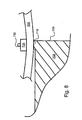
- Fig. 7 shows schematically the end 708 of the actuator rod to which the fibre 502 is attached. As illustrated in the figure, the end of the rod is provided with a shoulder 718, which the fibre 502 is to bear against.
- the end of the rod is shown in greater detail.
- the fibre 502 bears against the shoulder 718 and is fixed thereto by means of a contact block 728.
- the contact block 728 is tightened to the fibre 502 by means of a wire 730, in this case a tungsten wire, surrounding the entire rod 708.
- the purpose of the contact block 728 is to distribute the force from the wire 730, and to give a well defined interaction length L between the fibre 502 and the actuator rod.
- the placement and the length of the shoulder 718 requires some consideration.
- the placement of the shoulder 718 need to be close to the end of the actuator rod, which in practise means that the centre of the shoulder should be within a fraction of the shortest wavelength (the highest frequency) building up the acoustic pulse.
- the placement of the shoulder 718 can also be utilised to obtain a desired distortion, e.g. a low pass filtering, of the acoustic pulse when it enters the optical fibre 502.
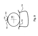
- Fig. 9 is a cross-sectional view of the attachment of the fibre 502 to the actuator rod 708.
- the fibre 502 is clamped to the rod 708 by means of the contact block 728, and fixed into place by the wire 730.
- the wire 730 is wound one full turn around the rod 708, and is tightened by a spring 732, as shown. This arrangement ensures a firm attachment of the fibre 502 to the actuator rod 708 in a well defined way.
- the proximity of the attachment point (i.e. the shoulder 718) to the end of the actuator rod 708, allows of reliable transfer of acoustic pulses into the fibre 502. More particularly, the closeness of the shoulder 718 to the end of the rod eliminates any influence from possible interference between a portion of the acoustic pulse propagating in one direction and a portion of the acoustic pulse propagating, after reflection, in the opposite direction.
- Fig. 10 shows an example of a longitudinal acoustic pulse, illustrating its shape as it propagates in the actuator rod 708 and in the optical fibre 502, according to the present invention.
- the pulse is anti-symmetric and plotted in terms of change in length ⁇ z.
- the shape shown is preferred, since such a shape gives a transmittance peak of close to 100 percent transmission of a certain wavelength.
Landscapes
- Physics & Mathematics (AREA)
- General Physics & Mathematics (AREA)
- Optics & Photonics (AREA)
- Nonlinear Science (AREA)
- Spectroscopy & Molecular Physics (AREA)
- Optical Communication System (AREA)
- Spectrometry And Color Measurement (AREA)
Description
- The present invention relates to optical Bragg-reflectors, and more particularly to the alteration of the reflective properties of optical Bragg-reflectors.
- The need for capacity in communications networks is increasing exponentially, and presently the capacity demands are doubled every eighteen months or even less. Efforts are being made in the telecom and computer business to meet this incredible expansion of bandwidth requirements.
- One obvious action is then to simply draw new optical cables between nodes of the network. However, this approach is costly and hardly a successful way of meeting the upcoming demands. Instead, measures are focused, when possible, on augmenting the capacity of existing fibre networks.
- One widespread method of achieving increased transfer capacity in existing fibre networks is wavelength division multiplexing (WDM). In WDM, a single optical fibre is used for the transmission of several channels of information, each channel being associated with a specific wavelength. For a background of this technology, the reader is directed to "A review of WDM technology and applications", Opt. Fiber Technol., 5, pp. 3-39, (1999).
- While the use of WDM in optical networks gives a substantial increase in transfer capacity, the complexity of the communications systems increases correspondingly. Furthermore, the number of physical components in each link of the network increases, the requirements on each component increase, and detecting and localising errors or imperfections in the network is rendered more difficult.
- The optical networks of today mainly use point-to-point communication, wherein electronically encoded information in one node of the network is transformed into optically encoded information, and then transferred, through a sequence of optical fibre amplifiers and optical transport fibres, to another node, where the optically encoded information is transformed back into electrically encoded information.
- However, this prior art is associated with major drawbacks and limitations.
- If, for instance, an error occurs in one of the fibre amplifiers, it is very hard to determine which amplifier, in the sequence of amplifiers, that is the faulty one.
- Furthermore, technology is being pushed towards communications systems, in which the optical signal is passed via all-optical switching nodes, where the signal is routed without any need for optical-to-electrical conversion or vice versa. Thus, if an error is detected in a receiving node of the communications network, it is extremely hard to localise the origin of error.
- If the light signal propagating in an optical transport fibre could be analysed in an accurate and simple fashion, without interfering with the signal, any flaws in the optical communications network could be detected at an early stage. In the prior art, such analysis has been too complicated, too expensive and too inaccurate to gain widespread acceptance.
- Obviously, it is of uttermost importance to be able to monitor the power spectrum of the light propagating in the optical transport fibre.
- It is known in the prior art to use a phase grating in an optical fibre in order to filter out one desired wavelength from a broadband light signal. A phase grating will reflect one predefined wavelength and leave other wavelengths essentially undisturbed.
- An optical phase grating is a structure of essentially periodically varying refractive index in an optically transparent medium. An overview of the technology is given in M. C. Hutley, "Diffraction gratings", Academic Press, London (1982). When light is incident on an optical phase grating, a small part of the incident light is reflected off each grating element (period). When a multiplicity of grating elements are arranged after each other (i.e. arranged as a phase grating), the total reflected light would be the sum of all these single reflections. The fraction of the incident light reflected off each grating element is determined by the depth (amplitude) of the refractive index modulation in the phase grating. The deeper the modulation is, the larger fraction of the incident light is reflected off each grating element. If the light is incident essentially normal to the grating (i.e. to the grating elements), the grating is said to act in the Bragg domain and is named Bragg grating. Light reflected off each grating element will thus overlap the light reflected off the other elements, causing interference. For a certain wavelength, all these reflections are in phase, whereby constructive interference is effected. Although each reflection is small, a substantial reflection is obtained due to the constructive interference. The wavelength for which constructive interference is effected is called the Bragg wavelength, λBragg, and is given by (at normal angle of incidence)

where n is the average of the refractive index and A is the grating period. - If the grating period, A, varies along the grating, the grating is said to be a chirped Bragg grating. In a chirped Bragg grating, different wavelengths are reflected in different portions of the grating, in fact making the Bragg grating a broadband reflector, a chirped Bragg-reflector.
-
US-A-6 052 179 discloses a system for determining the average wavelength of light transmitted through an optical fibre. In this system, a chirped Bragg grating is provided in an optical fibre, the grating having a modulation amplitude that varies from a first end to a second end of the fibre grating. Thus, the reflectivity at one wavelength is different from the reflectivity at another wavelength, since different wavelengths are reflected at different portions of the grating. Based on the output from two photo detectors - one detecting the light transmitted through the grating, the other acting as a reference - the average wavelength of the light transmitted through the grating is determined. However, this approach has several disadvantages. Firstly, the light to be analysed has to be divided into two separate fibres, which is a serious complication in itself. Secondly, only the average wavelength can be determined. There is no possibility for proper spectrum analysis by the system disclosed in the above reference. Furthermore, the system is intended for sensing applications, where external influence change the average wavelength coming into the system. - Previous attempts to alter the reflective properties of an optical Bragg grating include creation of an acousto-optic superlattice imposed on a chirped Bragg grating. Such an arrangement is described by Chen et al. in "Superchirped moire grating based on an acousto-optic superlattice with a chirped fiber Bragg grating", OPTICS LETTERS, Vol. 24, No. 22, pp. 1558-1560. According to this reference, multiple transmission peaks are obtained by superimposing an acoustic wave on a chirped Bragg grating. The spacing of the transmission peaks is varied by the acoustic frequency. However, this arrangement does not permit transmission of one single wavelength only, and the variation of the spacing of the transmission peaks by acoustic frequency is very limited. Such arrangement is also shown in
US-A-5,982,963 . - The present invention provides new methods and arrangements for establishing transmission of light through a reflecting Bragg grating, and for utilising such transmission for analysis of the characteristics of a light signal. The drawbacks and limitations associated with the prior art are effectively eliminated by a method and an arrangement of the general kind set forth in the accompanying claims.
- The present invention has further advantages, which will be apparent from the specification set forth below.
- It is a general object of the present invention to provide a method of establishing transmission of light through a broadband, chirped Bragg-reflector. The method can be used for analysis of the power spectrum of a light signal, as well as for other applications where it is desirable to transmit a certain wavelength component of light through a structure at a certain instant in time.
- Furthermore, it is an object of the present invention to provide a method and an arrangement for spectrum analysis of a light signal, which method and arrangement essentially eliminate the aforementioned drawbacks and limitations of the prior art. Briefly stated, this is obtained by establishing transmission of light through a chirped Bragg-reflector by means of a longitudinal acoustic pulse being present in the grating structure. The presence of the acoustic pulse alters the reflective properties of the Bragg-reflector, thus giving rise to transmission of a specific wavelength of light for each position of the acoustic pulse in the Bragg-reflector.
- According to a first aspect of the present invention, a method of establishing transmission of light through a chirped Bragg-reflector is provided, by which method a certain wavelength component is transmitted through the Bragg-reflector at a certain (corresponding) instant in time. In an unperturbed state, the Bragg-reflector is reflecting essentially all incident light within a predefined wavelength range. According to the invention, light is incident into an optical waveguide incorporating a chirped Bragg-reflector. The reflective properties of said Bragg-reflector are altered by sending a longitudinal acoustic pulse into said waveguide for propagation along the same. For each location of said acoustic pulse in the chirped Bragg-reflector, the reflectivity for a wavelength associated with said location in said Bragg-reflector is altered, thereby establishing transmission of the wavelength at issue.
- According to a second aspect of the present invention, a new method of analysing the power spectrum of a light signal is provided. The method of analysing the power spectrum is based on the aforementioned method of establishing transmission of light through a chirped Bragg-reflector. Briefly stated, analysis of the power spectrum is obtained by monitoring the light transmitted through the Bragg-reflector, and by subsequent analysis of the monitored signal.
- One advantage of this method is that it is sufficient to tap off only a small part (typically about, or less than, 1%) of the light propagating in an optical transport fibre into a secondary fibre. The light in the secondary fibre is then analysed, and the interfering effect on the transport fibre is negligible. The light is tapped off from the transport fibre by non-wavelength discriminating coupling means, as known in the art. By analysing the light in the secondary fibre by the method according to the present invention, very high accuracy is obtained in determining the power spectrum of the light signal propagating in said transport fibre. Furthermore, the light signal in the transport fibre is essentially undisturbed, apart from the 1% tapped off.
- Another advantage of the present invention is that it also allows of real time supervision of a fibre based communications system. The information obtained from the supervision can advantageously be utilised for controlling other equipment connected to said system, such as amplifiers, filters, etc. In-line amplifiers and filters can be controlled in a feedback configuration with a spectrum analyser according to the present invention.
- Yet another advantage of the present invention is that a wavelength scan of transmitted light is obtained, which is very convenient for spectrum analysis. The present invention can provide for repeated wavelength scans, thereby facilitating interpretation and analysis of the monitored signal.
- According to a third aspect of the present invention, an arrangement for measuring and characterising the power spectrum of a light signal propagating in an optical fibre is provided. Such an arrangement includes a chirped Bragg-reflector operating in accordance with the methods above.
- The present invention is based on the general insight that the reflective properties of a chirped Bragg grating (or chirped Bragg-reflector) can be altered by a longitudinal acoustic pulse propagating along the grating. More particularly, the present invention is further based on the deeper insight that a longitudinal acoustic pulse of carefully chosen shape propagating along the grating can give highly accurate, and wavelength separated in time, transmission through the chirped Bragg grating.
- According to one embodiment of the present invention, a method of establishing transmission of light through a chirped Bragg-reflector includes the steps of directing light into a light guiding structure provided with said Bragg-reflector, and sending a longitudinal acoustic pulse along said light guiding structure, thereby locally and temporarily altering the reflective properties of the Bragg-reflector for a certain wavelength corresponding to the momentary position of the travelling acoustic pulse.
- According to another embodiment of the present invention, an optical fibre is provided with a chirped Bragg grating. The fibre has an input end and an output end, for the input of a light signal into said fibre and for the output of a transmitted part of said light signal, respectively. Connected to the optical fibre is an acoustic actuator for the emission of a longitudinal acoustic pulse into said fibre. The acoustic pulse is given a shape that has the effect of lowering the reflectance of the chirped Bragg-reflector for a certain wavelength at a certain instant in time. Preferably, the acoustic pulse is given an anti-symmetric shape, whereby an etalon effect is achieved in the proximity of the travelling acoustic pulse, thereby locally lowering the reflectivity of the chirped Bragg-reflector to essentially zero.
- It is to be understood that a chirped Bragg-reflector is a grating structure having a spatially varying grating period. This means that different wavelengths of light are in resonance (i.e. are reflected) at different portions of the Bragg-reflector. The grating period of the chirped Bragg-reflector may vary continuously, stepwise or in any other way. The term "chirped" does only specify that the period varies along the grating.
- Furthermore, it is the effective grating period that is of interest. As known from before, the effective grating period is the actual physical period times the refractive index of the medium in which light propagates. Therefore, the effective grating period may be varied by means of a change in the actual physical period, by a change in refractive index, or by a combination of both.
- The following detailed description of preferred embodiments is better understood when read in conjunction with the accompanying schematic drawings, in which:
-
Fig. 1 is a schematic outline of the basic principle behind the present invention, -
Fig. 2 shows a typical transmittance profile of a chirped Bragg-reflector in an unperturbed state, -
Fig. 3 illustrates a transmittance peak, caused by the presence of an acoustic pulse in the chirped Bragg-reflector, that sweeps through the reflectance band of the Bragg-reflector, -
Fig. 4 shows a magnified picture of the transmittance peak caused by the presence of an acoustic pulse in the Bragg-reflector, -
Fig. 5 shows an overview of an arrangement for spectrum analysis, according to the present invention, -
Fig. 6 shows the acoustic actuator and the fibre arrangement, according to the present invention, -
Figs. 7-9 shows the attachment of the fibre to the acoustic actuator in greater detail, -
Fig. 10 shows the shape of an acoustic pulse in accordance with the present invention, and -
Fig. 11 shows a detector output signal, and illustrates a correlation interpretation method according to the present invention. - Typically, and in accordance with one embodiment of the present invention, a chirped Bragg-reflector is provided in an optical fibre. As described above, the chirped Bragg-reflector is a distributed structure that reflects light within a predefined wavelength range. The wavelength reflected in each portion of the distributed structure depends on the local period of the grating constituting the Bragg-reflector. The grating period is defined as the optical distance between two adjacent grating elements. The shorter the grating period is, the shorter is the wavelength that is reflected.
- The vacuum wavelength λBragg of an optical wave that is locally in resonance with the grating is defined by λBragg = 2ng(z)Λg(z), where ng(z) is the average refractive index of one grating period, Λg(z) is the local physical grating period, and z is the spatial co-ordinate along the grating. Consequently, the resonance wavelength (i.e. the wavelength that is reflected at a particular portion of the grating) may be varied by means of a change in the actual physical period, by a change in the refractive index, or by a combination of both.
- In a chirped grating, the grating period varies along the grating, usually in a steady fashion (e.g. from a short period to a longer period, or from a long period to a shorter period). The period can vary continuously or stepwise. In a portion of the grating (i.e. the chirped Bragg-reflector) where the grating period is short, a short wavelength is reflected, and in a portion of the grating where the grating period is long, a long wavelength is reflected. In effect, different wavelengths are reflected in different portions of the chirped Bragg-reflector.
- Compression and/or elongation of the fibre can alter the reflective properties of the chirped Bragg-reflector. According to the present invention, this is accomplished by means of a longitudinal acoustic pulse, which causes a temporary compression and/or elongation of the fibre as it propagates along the fibre. In fact, such compression or elongation introduces both refractive index changes and actual path changes, the latter however being predominant. The aggregate effect on light is a combination of the change in refractive index and the change of the actual period of the grating in the fibre. From a phenomenological point of view, the crucial quantity is the optical path traversed by the light in the fibre. The optical path is defined as actual, physical path multiplied by the refractive index of the medium in which the light is propagating. For example, an increase of the effective grating period in a Bragg grating in an optical fibre could be obtained either by increasing the refractive index of the fibre, or by increasing the physical length of the period (i.e. the fibre).
- When stretching or compressing an optical fibre provided with a Bragg-reflector, the change in refractive index is negligible compared to the actual change in physical path. Therefore, if any portion of a chirped Bragg-reflector is stretched, this portion will reflect a longer wavelength than it would do in its unperturbed state. This actually applies for any Bragg-reflector, even with a constant grating period.
- The basic principle behind the present invention will now be described in greater detail with reference to
fig. 1 . - An
optical fibre 10 incorporates, in thecore 102 thereof, a chirped Bragg grating 104. The Bragg grating is incorporated into the optical fibre by means of methods known in the art. Thefibre 10 has aninput end 11 and anoutput end 12, for receiving input of a light signal and for delivering an output signal, respectively. The chirped Bragg grating exhibit a modulation that is strong enough to reflect essentially all incident light within a predefined wavelength range when the grating is in an unperturbed state. Due to this fact, the chirped Bragg grating is referred to as a chirped Bragg-reflector. In this case, it is assumed that the Bragg-reflector reflects all light wavelengths between λ0 and λk. Any wavelength of light within this range will be reflected if sent into the optical fibre incorporating said Bragg-reflector. - In order to establish transmission of light within this wavelength range (λ0 to λk) through the chirped Bragg-reflector, a light signal is first directed into the
input end 11 of theoptical fibre 10, as is indicated by thearrow 111. If the optical fibre, and thus the chirped Bragg-reflector, is in an unperturbed state, the light will be reflected back towards theinput end 11, and no light will be transmitted to theoutput end 12. A longitudinalacoustic pulse 120 is then sent along the optical fibre. In this case, and as is indicated in the figure, the longitudinalacoustic pulse 120 has an anti-symmetric shape, thereby causing in one part a localised and temporary elongation of theoptical fibre 10, and in another part a localised and temporary compression of theoptical fibre 10. Theacoustic pulse 120 alters the reflective properties of the chirped Bragg-reflector 104, and effectively establishes transmission of light through theoptical fibre 10. - In
fig. 1 , the chirped Bragg-reflector is shown to have a grating period that decreases from left to right. This means, as described above, that a longer wavelength is reflected in the left portion of the Bragg-reflector than in the right portion of the Bragg-reflector. When the longitudinal acoustic pulse travels along the grating from left to right, and hence locally and temporarily alters the reflective properties of the reflector, longer wavelengths will be transmitted first, followed by shorter wavelengths. - The mechanism behind the alteration of the reflective properties of the chirped Bragg-reflector will now be described in more detail.
- The acoustic pulse that is sent along the optical fibre has one elongating part causing a temporary elongation of the optical fibre, and one compressing part causing a temporary compression of the optical fibre, as mentioned above. In the present example, the acoustic pulse is essentially anti-symmetric, each of said parts being equally important. When the acoustic pulse is sent along the chirped Bragg-reflector (the optical fibre) in a direction in which the grating exhibits a decreasing grating period, it is essential that the acoustic pulse has a leading portion that causes a decrease of the grating period (i.e. a portion that causes a compression of the optical fibre) and a trailing portion that causes an increase of the grating period (i.e a portion that causes an elongation of the optical fibre). The leading portion of the acoustic pulse will then temporarily alter the local grating period, such that the altered local grating period actually gives a reflection for a somewhat shorter wavelength than in its unperturbed state. The trailing portion of the acoustic pulse will at the same time temporarily alter the local grating period, such that the altered local grating period actually gives a reflection for a somewhat longer wavelength than in its unperturbed state. Effectively, a window is created where there is reduced or no reflection, since the grating period of the chirped Bragg-reflector is altered in such a way that there is no grating period giving reflection for a certain wavelength. As the longitudinal acoustic pulse propagates along the chirped Bragg-reflector, the above situation will successively apply for shorter wavelengths, thereby creating a wavelength scan of transmitted light.
- If the acoustic pulse propagates along the chirped Bragg-reflector in a direction with increasing grating period, the acoustic pulse should, of course, have the opposite phase in order to cause a similar effect as before.
- When the acoustic pulse is given an anti-symmetric shape with a sufficiently short rise time (or fall time) between the compressive and the elongating portion, an etalon effect is obtained, where the reflectivity for a certain wavelength drops essentially to zero.
- In the lower part of
fig. 1 , the acoustic pulse is shown in a co-ordinate system at two different instants. The compression/elongation is illustrated as a change in longitudinal dimension Δz at a first point in time t1 and a second point in time t2. At time t1, the acoustic pulse is in a first portion of the Bragg-reflector where the unperturbed grating period is large, hence causing transmission of a long wavelength λ1 through the optical fibre. At a later time t2, the acoustic pulse has propagated to a second portion of the Bragg-reflector where the unperturbed grating period is shorter than in the first portion, hence causing transmission of a shorter wavelength λ2 through the optical fibre. Consequently, the output power at theoutput end 12 of the optical fibre at a certain point in time is associated with the power of a corresponding wavelength. In this example, the output power at time t1, which is denoted P(t1) is associated with the power of the incident light at wavelength λ1, which is denoted P(λ1). Thus, P(t1) =P (λ1), P(t2) =P(λ2), etc., any losses neglected. - In some cases, a small leakage through the unperturbed Bragg-reflector can be allowed, since such leakage would be straightforward to compensate for.
-
Fig. 2 shows schematically the transmittance of the Bragg-reflector as a function of wavelength. Illustrated in the figure is a reflection band, where there is essentially no transmission. The full width at half maximum (FWHM) of this reflection band is, in the exemplary embodiment, 40 nm. Typically, some 30 nm of the reflection band exhibits no transmission at all in the unperturbed state of the Bragg-reflector, i.e. practically 100 percent reflection. However, it is perceivable to obtain almost any width of the reflection band by choosing the grating period and the chirp accordingly. -
Fig. 3 illustrates a narrow transmittance peak that sweeps through the reflection band as the acoustic pulse propagates along the Bragg-reflector. In the figure, the transmittance peak is shown to sweep from longer wavelengths to shorter (from right to left in the figure, as indicated by the arrow), which is the case when the acoustic pulse propagates through the chirped Bragg-reflector in a direction from a longer grating period to a shorter grating period. Of course, if the acoustic pulse was propagating in the opposite direction through the chirped Bragg-reflector, the transmittance peak would sweep in the opposite direction, i.e. from a shorter wavelength to a longer wavelength. When the transmittance peak sweeps through the reflection band of the chirped Bragg-reflector, a wavelength scan of transmitted wavelengths is effectively achieved. -
Fig. 4 is a magnified illustration of the transmittance peak. The width of the transmittance peak can be chosen by proper selection of chirp of the Bragg-reflector (i.e. the rate of change of the grating period) and the modulation depth of the grating. The transmittance peak could be as narrow as 40 pm. However, when the present invention is utilised in a spectrum analyser in a WDM system, a transmittance peak of about 0.1 nm (FWHM) is sufficient in order to separate the different channels. As indicated infig. 4 , the transmittance peak can reach 100 percent, by proper choice of system parameters. -
Fig. 5 shows a schematic overview of a preferred embodiment of an arrangement for analysing the power spectrum of a light signal, according to the present invention. - The arrangement is utilised for analysis of the power spectrum of a light signal propagating in an optical transport fibre. A small fraction (typically about 1 percent) of the light propagating in the optical transport fibre is tapped of by a fibre coupler. The light tapped of is subsequently directed into a fibre provided with a chirped Bragg-reflector. Transmission of light through the chirped Bragg-reflector is achieved in accordance with the inventive method described above, by means of sending an acoustic pulse along the fibre. The light thus transmitted is monitored and analysed, in order to provide spectrum analysis of the light signal directed into the fibre.
- The preferred arrangement according to the present invention will now be described in greater detail, with reference to
fig. 5 . - The arrangement is operatively connected to an
optical transport fibre 500 through afibre coupler 510. Thecoupler 510 is a tap coupler tapping off 1 percent of the power of the light propagating in theoptical transport fibre 500. Thecoupler 510 is non-discriminating in terms of wavelength, which means that each wavelength component propagating in thefibre 500 is tapped off with the same coupling factor. Effectively, the power spectrum of the 1 percent tapped off has the same profile as the power spectrum of the original light signal propagating in thetransport fibre 500, but at a lower peak power. - The light tapped off the
transport fibre 500 is directed into asecondary fibre 502, and incident upon a broadband Bragg-reflector 520 incorporated into thefibre 502, which Bragg-reflector operates as a broadband filter for the incident light. Only light within the reflectance band of thefiltering reflector 520 is reflected back into thesecondary fibre 502, the broadband Bragg-reflector 520 thus pre-filtering the light signal to be analysed. Typically, this pre-filtering of the light by means of thefiltering reflector 520 selects (i.e. filters out by reflection) the signals in the C- or L-band of the telecommunications bands. The reflected light is subsequently directed into a portion of the secondary fibre incorporating a second Bragg-reflector 550. The second Bragg-reflector 550 is a chirped Bragg-reflector reflecting essentially the same wavelength band as thefiltering reflector 520. - The second Bragg-
reflector 550 is utilised for establishing transmission of light towards aphotodetector 556 provided at the output end of thesecondary fibre 502. The transmission of light towards thephotodetector 556 is obtained by sending a longitudinal acoustic pulse along the portion of thesecondary fibre 502 incorporating the chirped Bragg-reflector 550, according to the present invention. By sending a longitudinal acoustic pulse along the chirped Bragg-grating 550, transmission through the secondaryoptical fibre 502 is achieved in a very precise fashion. The mechanism behind the transmission is described in detail above. - The arrangement for analysing the power spectrum, according to the present invention, includes an acoustic actuator (not shown in
fig. 5 ) for sending longitudinal acoustic pulses along the chirped Bragg-reflector 550 in the secondaryoptical fibre 502; aphotodetector 556 for detecting the power of the light transmitted through the Bragg-reflector 550;programmable logic 600, in the form of an FPGA (Field Programmable Gate Array), for storing the waveform of the actuating pulses, and for controlling other hardware and perform simple signal analysis; a digital to analogue converter 610 (DAC) for converting digitally encoded output from theFPGA 600 into analogue form; an analogue to digital converter 630 (ADC) for converting monitored analogue signals into digital form for further storing and processing; a memory 640 (Mem) for storing measurement data; a delay line 650 (Del) for sub-sampling data in order to improve measurement resolution; a clock circuit 620 (Clk) for supplying clock pulses to thelogic 600; a digital synthesiser circuit 622 (DDS) for tuning the clock frequency and thereby tuning the repetition rate of actuating pulses to the acoustic actuator; and a processing unit 660 (CPU) for processing data and for communicating with thelogic 600 and other peripherals. - The longitudinal acoustic pulse to be sent along the chirped Bragg-
reflector 550 is excited by the acoustic actuator (not shown infig. 5 , but shown in great detail infigs. 6-9 ) attached to thesecondary fibre 502. The supply of actuating pulses to the acoustic actuator is controlled by the programmable logic 600 (FPGA). In theFPGA 600, the waveform of the actuating pulses is stored in digital form. Afirst output 601 of theFPGA 600 is connected to a first input of a digital to analogue converter 610 (DAC). The DAC is operative to convert the digitally encoded waveform of the actuating pulses to an analogue waveform and to send the analogue output signal to anamplifier 612. The amplified output of theamplifier 612 is fed to the acoustic actuator as actuating pulses. Asecond output 602 of theFPGA 600 is connected to theamplifier 612 in order to provide control signals from theFPGA 600 to theamplifier 612. - The
FPGA 600 is triggered by clock pulses from a clock circuit 620 (Clk). The output of theclock circuit 620 is operatively connected to theFPGA 600 via the digital synthesiser circuit 622 (DDS). Thedigital synthesiser circuit 622 is operative to tune the frequency of theclock circuit 620 in order to obtain tuning capability of the actuating pulses to the acoustic actuator. In order to control theDDS 622, a third output 603 of theFPGA 600 is connected to the DDS. Theclock circuit 620 is also operatively connected, via said DDS, to theDAC 610 and to thedelay line 650 and theADC 630. - The
photodetector 556 is operative to detect the power of the output signal from thesecondary fibre 502, after transmission through the chirped Bragg-reflector 550. As described above, the output power at each instant corresponds to the power of a certain wavelength component in the light signal directed into thesecondary fibre 502. The light directed into the secondary fibre, in turn, having a one to one correspondence to the light propagating in theoptical transport fibre 500. Thephotodetector 556 is arranged to provide a detector output signal, associated with the power of the detected signal, to a preamplifier 632. The output signal from the preamplifier 632 is passed to theADC 630. TheADC 630 is operative to convert the amplified detector output signal into digitally encoded form and to provide the digitally encoded measurement data to thememory 640 for storing. Thedelay line 650 and the amplifier 632 (and thus the ADC 630) are controlled by theFPGA 600 through fourth 604 and fifth 605 outputs of the FPGA, respectively. - The contents of the
memory 640 is readable to theprogrammable logic 600. Theprogrammable logic 600 is arranged to read the stored measurement data from thememory 640 and to perform simple signal analysis of the stored data. The analysis performed by theprogrammable logic 600 is the basis for the control that thelogic 600 exerts on theDDS 622, thedelay line 650 as well as for the actuating pulses fed to theDAC 610. Furthermore, theprogrammable logic 600 can communicate with a processing unit 660 (CPU) in order to transfer measurement data for further processing and supervision of system performance. - The
processing unit 660 has amemory 662 for storing both processed and non-processed data. Also, the processing unit hasconnections 664 for communicating with other peripherals (not shown), such as a display device, a keyboard, an I/O-device for communicating with other apparatus, etc. - Furthermore, the output of the
filtering reflector 520 can advantageously be connected to a second arrangement according to the present invention. For example, if the C-band of the communications bands is filtered out by a first filtering reflector and analysed in a first arrangement according to the present invention, then a second arrangement can be coupled to the first, for analysing the power spectrum of light signals in the L-band of the communications bands. A person with ordinary skills in the art will find it straightforward to combine two arrangements according to the present invention, in order to analyse two different communications bands simultaneously. - The acoustic actuator and the supply of longitudinal acoustic pulses to the portion of the secondary
optical fibre 502 incorporating the chirped Bragg-reflector 550 will now be described in more detail with reference tofigs. 6-9 . -
Fig. 6 shows schematically theacoustic actuator module 700 and thesecondary fibre 502 attached thereto. - The acoustic actuator comprises a
piezo device 705, made from a piezo-electric material, arranged in arod piezo device 705 has two connectors attached to its surface for the supply of actuating pulses thereto. The piezo device is responsive to actuating pulses by changing its longitudinal size. Hence, when a voltage is applied to thepiezo device 705, the size of the device changes accordingly. If properly actuated, the acoustic actuator emits an acoustic pulse into therod 706, 708 (as indicated in the figure by the four solid arrows), the rod guiding said pulse towards its ends. Oneend 706 of the rod is provided with anacoustic attenuator 707, effectively damping the acoustic pulse to essentially zero amplitude. Theother end 708 of the rod is firmly attached to thefibre 502, thereby ensuring that the acoustic pulse, emitted by the acoustic actuator, is transferred to thefibre 502. When the acoustic pulse reaches thefibre end 709 of therod 708, some of the acoustic power is reflected back towards thepiezo device 705, and some of the acoustic power is transferred to thefibre 502. The part of the acoustic power that is reflected back into the rod passes through thepiezo device 705, and is effectively damped by theacoustic attenuator 707. This ensures that only one pulse is sent into thefibre 502 by each actuation of thepiezo device 705. - The acoustic pulse propagates along the
fibre 502, and thus along the chirped Bragg-reflector 550, thereby establishing transmission of light through the Bragg-reflector 550, and effectively causing a wavelength scan of wavelengths transmitted towards thedetector 556. - At the output end of the
secondary fibre 502, the fibre is clamped by aclamping block 702. Theclamping block 702 forms afirst reflection point 710, and is arranged to give a reflection of the acoustic pulse back towards therod 708 and theacoustic actuator 705. Furthermore, when the reflected acoustic pulse reaches the attachment of the fibre to the actuator, the pulse is again reflected; this time back towards the output end of the fibre. The attachment of the fibre to the actuator thereby forming asecond reflection point 720 for the acoustic pulse. - It is preferred that acoustic pulses are sent into the fibre repeatedly, in order to provide repeated scans of transmitted wavelengths. In this embodiment, an acoustic pulse is sent into the
fibre 502 at the time when the reflection in the fibre of a previous pulse reaches the attachment point between the rod and the fibre. The acoustic pulse propagating back and forth between the reflection points 710, 720 thereby achieves some additional amplitude each time the pulse reaches the reflection point at theactuator 720. Preferably, the reflection of the acoustic pulse at eachreflection point fibre 502 slightly off schedule, this unwanted, or untimely, acoustic pulse will eventually die away, thereby preventing the build-up of a systematic error. - As described above, it is essential that the phase of the acoustic pulse corresponds to the chirp of the Bragg-reflector, in order to give the desired result. Conveniently, the reflection of the acoustic pulse at each
reflection point - The dual-pass feature is also utilised for the actual interpretation of the detected light signals. In order to ascribe a certain wavelength to a certain instant, i.e. to an output signal from the detector at a certain time, a correlation procedure is utilised. A first pass of the acoustic pulse through the chirped Bragg-reflector causes transmission of a first spectrum profile. A second pass of the acoustic pulse through the chirped Bragg-reflector, now in the opposite direction, causes transmission of a second spectrum profile, which is essentially the same spectrum profile as the first spectrum profile, but in reversed timely order since the acoustic pulse now propagates in the opposite direction through the Bragg-reflector. The acoustic pulse is then reflected back towards the Bragg-reflector a third time, causing transmission of a third spectrum profile. The third spectrum profile is essentially identical to the first spectrum profile if the first and the third pass of the acoustic pulse through the chirped Bragg-reflector are sufficiently close in time (since the light signal to be analysed have not had time to change significantly between the first and the third pass).
- Now, a correlation between the first spectrum profile and the third spectrum profile gives at hand a first time interval, corresponding to the passage time of the acoustic pulse to complete one round trip in the fibre between the two reflection points. This first time interval should be constant, unless the length of the fibre is changed by, for example, a temperature change (i.e. thermal expansion or contraction of the fibre).
- In order to correlate the second spectrum profile and the first spectrum profile, the second profile must first be mirrored. Mirroring of the second spectrum profile about a reference wavelength, and subsequent correlation between the mirrored spectrum and the first spectrum, gives at hand a second time interval, corresponding to the time elapsed between one transmission of said reference wavelength, and the following transmission of the same reference wavelength during the following passage of the acoustic pulse through the chirped Bragg-reflector.
- The relationship between the first time interval and the second time interval is constant, even if the length of the fibre changes due to, for example, temperature changes. This means that there is a unique number (equal to the relationship between the first and the second time intervals) associated with each reference wavelength. By measuring the time intervals, calculating the relationship, and comparing the relationship with a stored value in a look-up table, the corresponding real value for each reference wavelength is obtained.
- The analysis of the spectrum profiles is preferably done after sampling the detector output signal into a digitally encoded form, each time interval thus corresponding to a certain number of samples.
- Furthermore, by monitoring said first time interval, a change in fibre length due to, for example, temperature changes can be detected. Consequently, the repetition rate of the acoustic pulses can be controlled to comply with the length of the fibre. Hence, resonant feeding of acoustic pulses from the actuator is possible even if the length of the fibre is changed.
- By basic symmetry considerations, it is obvious that the length of the
piezo device 705 must be carefully selected to suit the desired pulse length of the acoustic pulse to be sent into thefibre 502. A person with ordinary skills in the art will find the suitable length of the piezo device by simple tests and/or computer simulations. - Having described the general features of the acoustic actuator, the attachment of the
fibre 502 thereto will now be described in more detail with reference tofigs. 7-9 . -
Fig. 7 shows schematically theend 708 of the actuator rod to which thefibre 502 is attached. As illustrated in the figure, the end of the rod is provided with ashoulder 718, which thefibre 502 is to bear against. - In
fig. 8 , the end of the rod is shown in greater detail. Thefibre 502 bears against theshoulder 718 and is fixed thereto by means of acontact block 728. Thecontact block 728 is tightened to thefibre 502 by means of awire 730, in this case a tungsten wire, surrounding theentire rod 708. The purpose of thecontact block 728 is to distribute the force from thewire 730, and to give a well defined interaction length L between thefibre 502 and the actuator rod. - The placement and the length of the
shoulder 718 requires some consideration. The placement of theshoulder 718 need to be close to the end of the actuator rod, which in practise means that the centre of the shoulder should be within a fraction of the shortest wavelength (the highest frequency) building up the acoustic pulse. With such an arrangement of the shoulder, the distortion of the acoustic pulse when transferred from the rod to the fibre is minimised. The placement of theshoulder 718 can also be utilised to obtain a desired distortion, e.g. a low pass filtering, of the acoustic pulse when it enters theoptical fibre 502. -
Fig. 9 is a cross-sectional view of the attachment of thefibre 502 to theactuator rod 708. Thefibre 502 is clamped to therod 708 by means of thecontact block 728, and fixed into place by thewire 730. Thewire 730 is wound one full turn around therod 708, and is tightened by aspring 732, as shown. This arrangement ensures a firm attachment of thefibre 502 to theactuator rod 708 in a well defined way. - Thus, the proximity of the attachment point (i.e. the shoulder 718) to the end of the
actuator rod 708, allows of reliable transfer of acoustic pulses into thefibre 502. More particularly, the closeness of theshoulder 718 to the end of the rod eliminates any influence from possible interference between a portion of the acoustic pulse propagating in one direction and a portion of the acoustic pulse propagating, after reflection, in the opposite direction. -
Fig. 10 shows an example of a longitudinal acoustic pulse, illustrating its shape as it propagates in theactuator rod 708 and in theoptical fibre 502, according to the present invention. In the shown example, the pulse is anti-symmetric and plotted in terms of change in length Δz. The shape shown is preferred, since such a shape gives a transmittance peak of close to 100 percent transmission of a certain wavelength. - Although the present invention has been described with reference to the drawings and by way of preferred embodiments, it is to be understood that the embodiments described can undergo several alterations and modifications without departing from the scope of the invention as claimed in the accompanying claims.
Claims (31)
- A method of establishing transmission of light through a light guiding structure (10) incorporating a chirped Bragg-reflector (104), comprising the steps of
directing light into an input end (11) of said light guiding structure (10), and characterised by
sending a longitudinal acoustic pulse (120) into said light guiding structure (10) for propagation along the same, the acoustic pulse (120) being such that, for each location of said acoustic pulse (120) said Bragg-reflector (104), the reflectivity for a wavelength associated with said location in said Bragg-reflector is altered. - The method as set forth in claim 1, wherein the propagation of the acoustic pulse along said light guiding structure causes an alteration of a local grating period of said chirped Bragg-reflector to provide, for each location of said acoustic pulse in said Bragg-reflector, transmission of a wavelength associated with said location, thereby providing a wavelength scan of transmitted wavelengths as the acoustic pulse propagates along said Bragg-reflector.
- The method as set forth in claim 1, wherein the acoustic pulse has a first part and a second part, said first part causing a temporary increase of the local grating period of the chirped Bragg-reflector, and said second part causing a temporary decrease of the local grating period of said Bragg-reflector.
- The method as set forth in claim 3, wherein the portion of said chirped Bragg-reflector containing the first part of said acoustic pulse has, in its unperturbed state, a longer grating period than the portion of said Bragg-reflector containing the second part of said acoustic pulse.
- The method as set forth in claim 1, wherein the step of sending a longitudinal acoustic pulse through the light guiding structure is performed repeatedly, whereby a plurality of acoustic pulses is sent through said light guiding structure, of which plurality of acoustic pulses only one acoustic pulse is present in the chirped Bragg-reflector at any one instant.
- The method as set forth in claim 1, further comprising the step of
detecting, at an output end (12) of the light guiding structure, the intensity of the light transmitted, the light detected at a certain instant in time corresponding to a certain wavelength, thereby allowing analysis of the power spectrum of the light directed into said light guiding structure. - The method as set forth in claim 6, further including the step of
pre-filtering the light to be directed into the light guiding structure by means of a broadband filter, said filter passing essentially the same wavelength range as the chirped Bragg-reflector reflects. - The method as set forth in claim 3, wherein either one of the first and the second part of the acoustic pulse is predominant, the acoustic pulse thereby causing mainly an increase or mainly a decrease of the local grating period of the Bragg-reflector.
- The method as set forth in claim 1, wherein said light guiding structure is the core of an optical fibre.
- An arrangement for analysing the power spectrum of a light signal, comprising
a light guiding structure, having an input end and an output end;
a chirped Bragg-reflector (550,104) in said light guiding structure, which chirped Bragg-reflector is provided between the input end and the output end;
an acoustic actuator (700) connected to said light guiding structure; and
a detector (556) provided at the output end of said light guiding structure, said detector delivering a detector output signal, characterised in that
the input end of said light guiding structure is arranged to receive the light signal to be analysed, said acoustic actuator (700) is operative to emit a longitudinal acoustic pulse for propagation along the light guiding structure, and said detector (556) is operative to detect the light thus transmitted through said Bragg-reflector (550) and to provide a detector output signal associated with the power spectrum of said light signal. - The arrangement as set forth in claim 10, further including a broadband filter (520) provided in the light path prior to the input end of the light guiding structure, said filter being arranged to pass only light of a desired wavelength range to said light guiding structure.
- The arrangement as set forth in claim 11, wherein the broadband filter is arranged to pass essentially the same wavelength range as the chirped Bragg-reflector reflects.
- The arrangement as set forth in any one of the claims 10 - 12, further comprising a logic unit (600) connected to said acoustic actuator, for supplying actuating pulses to said acoustic actuator.
- The arrangement as set forth in claim 13, further comprising a processing unit (660), which is arranged to control the operation of the logic unit (600).
- The arrangement as set forth in claim 13, wherein the logic unit is arranged to perform basic signal analysis of the detector output signal.
- The arrangement as set forth in claim 15, wherein the basic signal analysis performed by the logic unit is utilised for the control of the acoustic actuator.
- The arrangement as set forth in claim 10, wherein the light guiding structure is clamped at a first point (710) and a second point (720) thereof, thereby defining a first and a second reflection point, at which reflection points the acoustic pulse is reflected, and effectively providing multiple passages of the acoustic pulse through the Bragg-reflector.
- The arrangement as set forth in claim 17, wherein the acoustic actuator is connected to the light guiding structure at either one of the first and the second reflection points.
- The arrangement as set forth in claim 18, wherein the acoustic actuator is arranged to emit a longitudinal acoustic pulse into the light guiding structure at the time when a previous acoustic pulse, after its reflection, arrives at the point where said actuator is connected to the light guiding structure.
- The method of claim 1 for analysing the power spectrum of a light signal, wherein the light signal to be analysed is directed into the light guiding structure incorporating the chirped Bragg-reflector, and further comprising the steps of
monitoring the light thus transmitted through said light guiding structure, and
analysing the monitored light, in order to obtain a power spectrum analysis of the light signal directed into the light guiding structure. - The method as set forth in claim 20, wherein the propagation of the acoustic pulse along said light guiding structure causes an alteration of the local grating period of said chirped Bragg-reflector to provide, for each location of said acoustic pulse in said Bragg-reflector, transmission of a wavelength associated with said location, thereby providing a wavelength scan of transmitted wavelengths as the acoustic pulse propagates along said Bragg-reflector.
- The method as set forth in claim 20, wherein the acoustic pulse has a first part and a second part, said first part causing a temporary increase of the local grating period of the Bragg-reflector, and said second part causing a temporary decrease of the local grating period of said Bragg-reflector.
- The method as set forth in claim 22, wherein the portion of said chirped Bragg-reflector containing the first part of said acoustic pulse has, in its unperturbed state, a longer grating period than the portion of said Bragg-reflector containing the second part of said acoustic pulse.
- The method as set forth in claim 20, wherein the step of monitoring the light transmitted through the light guiding structure includes detecting said transmitted light by means of a detector, the detector providing a detector output signal associated with the power of the transmitted light signal.
- The method as set forth in claim 20, wherein said light guiding structure is the core of an optical fibre.
- The method as set forth in claim 24, wherein the step of sending a longitudinal acoustic pulse along the light guiding structure is performed repeatedly, whereby a plurality of acoustic pulses is sent along said light guiding structure, of which plurality of acoustic pulses only one acoustic pulse is present in the chirped Bragg-reflector at any one instant.
- The method as set forth in claim 26, wherein each acoustic pulse is reflected back and forth between two reflection points in the light guiding structure, each successive pulse of said plurality of acoustic pulses being sent into the light guiding structure at the time when the previous acoustic pulse, after its reflection, reaches the acoustic actuator.
- The method as set forth in claim 27, wherein the wavelength scan obtained by a passage of an acoustic pulse through the chirped Bragg-reflector is utilised together with a subsequent wavelength scan for spectrum analysis of the light signal directed into the light guiding structure.
- The method as set forth in claim 28, wherein correlation between different wavelength scans in the detector output signal is performed in order to interpret said detector output signals, to ascribe the detector output at a certain instant to a specific wavelength.
- The method as set forth in claim 20, further including the step of
pre-filtering the light to be directed into the light guiding structure by means of a broadband filter, said filter passing essentially the same wavelength range as the chirped Bragg-reflector reflects. - The method as set forth in claim 24, wherein the detector output signal is fed to a logic unit, said logic unit processing said detector output signal to provide a logic unit output signal indicative of the power spectrum of the light signal directed into the light guiding structure.
Applications Claiming Priority (3)
| Application Number | Priority Date | Filing Date | Title |
|---|---|---|---|
| SE0002415A SE516645C2 (en) | 2000-06-27 | 2000-06-27 | Method and arrangement of Bragg optical reflectors |
| SE0002415 | 2000-06-27 | ||
| PCT/SE2001/001415 WO2002001282A1 (en) | 2000-06-27 | 2001-06-26 | Method and arrangement in connection with optical bragg-reflectors |
Publications (2)
| Publication Number | Publication Date |
|---|---|
| EP1303784A1 EP1303784A1 (en) | 2003-04-23 |
| EP1303784B1 true EP1303784B1 (en) | 2015-07-29 |
Family
ID=20280266
Family Applications (1)
| Application Number | Title | Priority Date | Filing Date |
|---|---|---|---|
| EP01945854.6A Expired - Lifetime EP1303784B1 (en) | 2000-06-27 | 2001-06-26 | Method and arrangement in connection with optical bragg-reflectors |
Country Status (6)
| Country | Link |
|---|---|
| EP (1) | EP1303784B1 (en) |
| JP (1) | JP4614618B2 (en) |
| AU (1) | AU2001267964A1 (en) |
| CA (1) | CA2413106A1 (en) |
| SE (1) | SE516645C2 (en) |
| WO (1) | WO2002001282A1 (en) |
Families Citing this family (2)
| Publication number | Priority date | Publication date | Assignee | Title |
|---|---|---|---|---|
| US8315282B2 (en) | 2005-01-20 | 2012-11-20 | Massachusetts Institute Of Technology | Fourier domain mode locking: method and apparatus for control and improved performance |
| EP1839375B1 (en) * | 2005-01-20 | 2014-06-04 | Massachusetts Institute of Technology | Mode locking methods and apparatus |
Family Cites Families (4)
| Publication number | Priority date | Publication date | Assignee | Title |
|---|---|---|---|---|
| US5502782A (en) * | 1995-01-09 | 1996-03-26 | Optelecom, Inc. | Focused acoustic wave fiber optic reflection modulator |
| US5982963A (en) * | 1997-12-15 | 1999-11-09 | University Of Southern California | Tunable nonlinearly chirped grating |
| US6052179A (en) * | 1998-04-14 | 2000-04-18 | Physical Optics Corporation | Method and system for determining the wavelength of light transmitted through an optical fiber |
| US6052497A (en) * | 1998-05-22 | 2000-04-18 | Lucent Technologies Inc. | System comprising acousto-optic tunable filter |
-
2000
- 2000-06-27 SE SE0002415A patent/SE516645C2/en not_active IP Right Cessation
-
2001
- 2001-06-26 EP EP01945854.6A patent/EP1303784B1/en not_active Expired - Lifetime
- 2001-06-26 AU AU2001267964A patent/AU2001267964A1/en not_active Abandoned
- 2001-06-26 CA CA002413106A patent/CA2413106A1/en not_active Abandoned
- 2001-06-26 WO PCT/SE2001/001415 patent/WO2002001282A1/en not_active Ceased
- 2001-06-26 JP JP2002506159A patent/JP4614618B2/en not_active Expired - Fee Related
Also Published As
| Publication number | Publication date |
|---|---|
| SE516645C2 (en) | 2002-02-05 |
| CA2413106A1 (en) | 2002-01-03 |
| JP2004502195A (en) | 2004-01-22 |
| WO2002001282A1 (en) | 2002-01-03 |
| EP1303784A1 (en) | 2003-04-23 |
| SE0002415L (en) | 2001-12-28 |
| SE0002415D0 (en) | 2000-06-27 |
| AU2001267964A1 (en) | 2002-01-08 |
| JP4614618B2 (en) | 2011-01-19 |
Similar Documents
| Publication | Publication Date | Title |
|---|---|---|
| US6356684B1 (en) | Adjustable optical fiber grating dispersion compensators | |
| EP0772265B1 (en) | OTDR apparatus | |
| EP0221560B1 (en) | Coupling device for single mode optical fiber and communications system comprising same | |
| US6271952B1 (en) | Polarization mode dispersion compensation | |
| CA2209144C (en) | Variable attenuator | |
| EP1554619B1 (en) | Compensating for chromatic dispersion in optical fibers | |
| EP0256809A2 (en) | Optical fiber transmission system having dispersion transformer | |
| KR20010033183A (en) | Tunable nonlinearly chirped grating | |
| US6510256B1 (en) | Method and arrangement in connection with optical bragg-reflectors | |
| US6594410B2 (en) | Wide range tunable optical filter | |
| US6674773B1 (en) | Multi-wavelength Raman laser | |
| US6865319B2 (en) | Optical structure for the compensation of chromatic dispersion in a light signal | |
| US6619864B2 (en) | Optical channel monitor with continuous gas cell calibration | |
| Ortega et al. | Analysis of a microwave time delay line based on a perturbed uniform fiber Bragg grating operating at constant wavelength | |
| US20030161580A1 (en) | Optical structure for the compensation of chromatic dispersion and dispersion slope in a light signal | |
| CN111679453B (en) | Microwave photonic filter based on few-mode fiber Bragg grating | |
| CA2413106A1 (en) | Method and arrangement in connection with optical bragg-reflectors | |
| WO2003096106A1 (en) | Scanning light source | |
| US20020181106A1 (en) | System and method for tunable dispersion compensation | |
| JP2003107417A (en) | Adaptive dispersion compensating element and control method thereof | |
| KR100506229B1 (en) | Dispersion compensator with planar lightwave circuit structure | |
| JP2001264167A (en) | Optical spectrum analyzer | |
| US6647030B1 (en) | Tuning of optical fiber components | |
| WO2001054238A1 (en) | Cascaded raman resonator with sampled grating structure | |
| De Souza et al. | Dual-operation Q-switched erbium-doped fibre laser for distributed fibre sensing |
Legal Events
| Date | Code | Title | Description |
|---|---|---|---|
| PUAI | Public reference made under article 153(3) epc to a published international application that has entered the european phase |
Free format text: ORIGINAL CODE: 0009012 |
|
| 17P | Request for examination filed |
Effective date: 20021213 |
|
| AK | Designated contracting states |
Designated state(s): AT BE CH CY DE DK ES FI FR GB GR IE IT LI LU MC NL PT SE TR |
|
| AX | Request for extension of the european patent |
Extension state: AL LT LV MK RO SI |
|
| RAP1 | Party data changed (applicant data changed or rights of an application transferred) |
Owner name: PROXIMION FIBER SYSTEMS AB |
|
| 17Q | First examination report despatched |
Effective date: 20060331 |
|
| GRAP | Despatch of communication of intention to grant a patent |
Free format text: ORIGINAL CODE: EPIDOSNIGR1 |
|
| INTG | Intention to grant announced |
Effective date: 20150305 |
|
| GRAS | Grant fee paid |
Free format text: ORIGINAL CODE: EPIDOSNIGR3 |
|
| GRAA | (expected) grant |
Free format text: ORIGINAL CODE: 0009210 |
|
| AK | Designated contracting states |
Kind code of ref document: B1 Designated state(s): AT BE CH CY DE DK ES FI FR GB GR IE IT LI LU MC NL PT SE TR |
|
| REG | Reference to a national code |
Ref country code: GB Ref legal event code: FG4D |
|
| REG | Reference to a national code |
Ref country code: CH Ref legal event code: EP |
|
| REG | Reference to a national code |
Ref country code: AT Ref legal event code: REF Ref document number: 739756 Country of ref document: AT Kind code of ref document: T Effective date: 20150815 |
|
| REG | Reference to a national code |
Ref country code: IE Ref legal event code: FG4D |
|
| REG | Reference to a national code |
Ref country code: DE Ref legal event code: R096 Ref document number: 60149484 Country of ref document: DE |
|
| REG | Reference to a national code |
Ref country code: AT Ref legal event code: MK05 Ref document number: 739756 Country of ref document: AT Kind code of ref document: T Effective date: 20150729 |
|
| REG | Reference to a national code |
Ref country code: NL Ref legal event code: MP Effective date: 20150729 |
|
| PG25 | Lapsed in a contracting state [announced via postgrant information from national office to epo] |
Ref country code: GR Free format text: LAPSE BECAUSE OF FAILURE TO SUBMIT A TRANSLATION OF THE DESCRIPTION OR TO PAY THE FEE WITHIN THE PRESCRIBED TIME-LIMIT Effective date: 20151030 Ref country code: FI Free format text: LAPSE BECAUSE OF FAILURE TO SUBMIT A TRANSLATION OF THE DESCRIPTION OR TO PAY THE FEE WITHIN THE PRESCRIBED TIME-LIMIT Effective date: 20150729 |
|
| PG25 | Lapsed in a contracting state [announced via postgrant information from national office to epo] |
Ref country code: ES Free format text: LAPSE BECAUSE OF FAILURE TO SUBMIT A TRANSLATION OF THE DESCRIPTION OR TO PAY THE FEE WITHIN THE PRESCRIBED TIME-LIMIT Effective date: 20150729 Ref country code: PT Free format text: LAPSE BECAUSE OF FAILURE TO SUBMIT A TRANSLATION OF THE DESCRIPTION OR TO PAY THE FEE WITHIN THE PRESCRIBED TIME-LIMIT Effective date: 20151130 Ref country code: SE Free format text: LAPSE BECAUSE OF FAILURE TO SUBMIT A TRANSLATION OF THE DESCRIPTION OR TO PAY THE FEE WITHIN THE PRESCRIBED TIME-LIMIT Effective date: 20150729 Ref country code: AT Free format text: LAPSE BECAUSE OF FAILURE TO SUBMIT A TRANSLATION OF THE DESCRIPTION OR TO PAY THE FEE WITHIN THE PRESCRIBED TIME-LIMIT Effective date: 20150729 |
|
| PG25 | Lapsed in a contracting state [announced via postgrant information from national office to epo] |
Ref country code: NL Free format text: LAPSE BECAUSE OF FAILURE TO SUBMIT A TRANSLATION OF THE DESCRIPTION OR TO PAY THE FEE WITHIN THE PRESCRIBED TIME-LIMIT Effective date: 20150729 |
|
| PG25 | Lapsed in a contracting state [announced via postgrant information from national office to epo] |
Ref country code: IT Free format text: LAPSE BECAUSE OF FAILURE TO SUBMIT A TRANSLATION OF THE DESCRIPTION OR TO PAY THE FEE WITHIN THE PRESCRIBED TIME-LIMIT Effective date: 20150729 Ref country code: DK Free format text: LAPSE BECAUSE OF FAILURE TO SUBMIT A TRANSLATION OF THE DESCRIPTION OR TO PAY THE FEE WITHIN THE PRESCRIBED TIME-LIMIT Effective date: 20150729 |
|
| REG | Reference to a national code |
Ref country code: DE Ref legal event code: R097 Ref document number: 60149484 Country of ref document: DE |
|
| PLBE | No opposition filed within time limit |
Free format text: ORIGINAL CODE: 0009261 |
|
| STAA | Information on the status of an ep patent application or granted ep patent |
Free format text: STATUS: NO OPPOSITION FILED WITHIN TIME LIMIT |
|
| 26N | No opposition filed |
Effective date: 20160502 |
|
| PG25 | Lapsed in a contracting state [announced via postgrant information from national office to epo] |
Ref country code: BE Free format text: LAPSE BECAUSE OF FAILURE TO SUBMIT A TRANSLATION OF THE DESCRIPTION OR TO PAY THE FEE WITHIN THE PRESCRIBED TIME-LIMIT Effective date: 20150729 |
|
| REG | Reference to a national code |
Ref country code: DE Ref legal event code: R119 Ref document number: 60149484 Country of ref document: DE |
|
| PG25 | Lapsed in a contracting state [announced via postgrant information from national office to epo] |
Ref country code: MC Free format text: LAPSE BECAUSE OF FAILURE TO SUBMIT A TRANSLATION OF THE DESCRIPTION OR TO PAY THE FEE WITHIN THE PRESCRIBED TIME-LIMIT Effective date: 20150729 |
|
| REG | Reference to a national code |
Ref country code: CH Ref legal event code: PL |
|
| GBPC | Gb: european patent ceased through non-payment of renewal fee |
Effective date: 20160626 |
|
| REG | Reference to a national code |
Ref country code: IE Ref legal event code: MM4A |
|
| REG | Reference to a national code |
Ref country code: FR Ref legal event code: ST Effective date: 20170228 |
|
| PG25 | Lapsed in a contracting state [announced via postgrant information from national office to epo] |
Ref country code: DE Free format text: LAPSE BECAUSE OF NON-PAYMENT OF DUE FEES Effective date: 20170103 Ref country code: FR Free format text: LAPSE BECAUSE OF NON-PAYMENT OF DUE FEES Effective date: 20160630 Ref country code: CH Free format text: LAPSE BECAUSE OF NON-PAYMENT OF DUE FEES Effective date: 20160630 Ref country code: LI Free format text: LAPSE BECAUSE OF NON-PAYMENT OF DUE FEES Effective date: 20160630 |
|
| PG25 | Lapsed in a contracting state [announced via postgrant information from national office to epo] |
Ref country code: IE Free format text: LAPSE BECAUSE OF NON-PAYMENT OF DUE FEES Effective date: 20160626 Ref country code: GB Free format text: LAPSE BECAUSE OF NON-PAYMENT OF DUE FEES Effective date: 20160626 |
|
| PG25 | Lapsed in a contracting state [announced via postgrant information from national office to epo] |
Ref country code: CY Free format text: LAPSE BECAUSE OF FAILURE TO SUBMIT A TRANSLATION OF THE DESCRIPTION OR TO PAY THE FEE WITHIN THE PRESCRIBED TIME-LIMIT Effective date: 20150729 |
|
| PG25 | Lapsed in a contracting state [announced via postgrant information from national office to epo] |
Ref country code: TR Free format text: LAPSE BECAUSE OF FAILURE TO SUBMIT A TRANSLATION OF THE DESCRIPTION OR TO PAY THE FEE WITHIN THE PRESCRIBED TIME-LIMIT Effective date: 20150729 Ref country code: LU Free format text: LAPSE BECAUSE OF NON-PAYMENT OF DUE FEES Effective date: 20160626 |