EP1303155B1 - System, method and device for determining the position of a portable device in a wireless communication system - Google Patents
System, method and device for determining the position of a portable device in a wireless communication system Download PDFInfo
- Publication number
- EP1303155B1 EP1303155B1 EP01124500A EP01124500A EP1303155B1 EP 1303155 B1 EP1303155 B1 EP 1303155B1 EP 01124500 A EP01124500 A EP 01124500A EP 01124500 A EP01124500 A EP 01124500A EP 1303155 B1 EP1303155 B1 EP 1303155B1
- Authority
- EP
- European Patent Office
- Prior art keywords
- message
- beacon
- portable
- identification code
- portable devices
- Prior art date
- Legal status (The legal status is an assumption and is not a legal conclusion. Google has not performed a legal analysis and makes no representation as to the accuracy of the status listed.)
- Expired - Lifetime
Links
- 238000004891 communication Methods 0.000 title claims abstract description 27
- 238000000034 method Methods 0.000 title claims description 7
- 230000005540 biological transmission Effects 0.000 description 5
- 238000010586 diagram Methods 0.000 description 2
- 230000006870 function Effects 0.000 description 2
- 238000005516 engineering process Methods 0.000 description 1
- 239000000284 extract Substances 0.000 description 1
- 230000004044 response Effects 0.000 description 1
Images


Classifications
-
- H—ELECTRICITY
- H04—ELECTRIC COMMUNICATION TECHNIQUE
- H04W—WIRELESS COMMUNICATION NETWORKS
- H04W64/00—Locating users or terminals or network equipment for network management purposes, e.g. mobility management
-
- G—PHYSICS
- G01—MEASURING; TESTING
- G01S—RADIO DIRECTION-FINDING; RADIO NAVIGATION; DETERMINING DISTANCE OR VELOCITY BY USE OF RADIO WAVES; LOCATING OR PRESENCE-DETECTING BY USE OF THE REFLECTION OR RERADIATION OF RADIO WAVES; ANALOGOUS ARRANGEMENTS USING OTHER WAVES
- G01S1/00—Beacons or beacon systems transmitting signals having a characteristic or characteristics capable of being detected by non-directional receivers and defining directions, positions, or position lines fixed relatively to the beacon transmitters; Receivers co-operating therewith
- G01S1/02—Beacons or beacon systems transmitting signals having a characteristic or characteristics capable of being detected by non-directional receivers and defining directions, positions, or position lines fixed relatively to the beacon transmitters; Receivers co-operating therewith using radio waves
- G01S1/68—Marker, boundary, call-sign, or like beacons transmitting signals not carrying directional information
Definitions
- the present invention relates to a system for wireless communication in accordance with the preamble of claim 1. Examples of such a system are described in EP-A-0 930 514 and US-A-6 055 434 .
- the invention in particular relates to the field of wireless communication systems of the kind where a number of portables communicate through a number of base stations, such as in a DECT-system (Digital Enhanced Cordless Telecommunication) .
- DECT-system Digital Enhanced Cordless Telecommunication
- Wireless communication systems with portable devices are many times used in an environment where the ability to transmit alarms is required. Examples of such environments are prisons, care units, etc. Other examples are guards or watchmen patrolling an area such as an industry, maids in a hotel, etc.
- An object of the present invention is to provide a cost efficient way of determining the position of a user in a wireless communication system, alleviating some of the problems mentioned above.
- the beacon is arranged to communicate according to the communication standard used by the system and to transmit a message directly receivable by portables located sufficiently close to the beacon.
- the message comprises an identification of said beacon.
- the beacon can advantageously be provided in a system of the kind mentioned by way of introduction.
- the invention further provides a method for determining the position of a portable within a wireless communication system.
- a beacon is arranged to transmit a message including an identification code that is receivable by a portable.
- a received identification code provides information relating to the position of the portable.
- the beacon has the same technical properties as the portables, with the exception of being physically fixed in one position. This means they do not need to be connected to the system in the way a base station is, and are each identified by the system as any other portable. The cost for each beacon is thus significantly reduced.
- each beacon can preferably be contacted via a base station, just like a portable. This allows the system to interact directly with the beacons, for example to supervise their function. This can be important in an environment where sabotage can be expected, such as in a prison.
- the identification code can be stored in the portable. At a suitable time, for example when an alarm is sent from the portable, the identification code can be transferred to the system, thereby indicating the position of the portable. It should be noted that the expression "identification code” here is used relating to the identity of the beacon, and not the portable.
- the portable In a preferred embodiment, several consecutively received identification codes are stored by the portable. When the position of a portable is determined, the most recently stored identification code represents the portable's current location, and the preceding identification codes represent the path it has followed. This information can be used to establish in what direction the portable is being moved.
- a received identification code is transmitted to a central unit as soon as a new, not earlier received, identification code is received. There, it can be used to continually monitor the position of a portable. By logging several transmitted identification codes, the central unit can provide information about the movements of portables in the system.
- the identification code is only accepted (e.g. stored or transmitted) by the portable if the message is received with at least a predetermined signal strength. This ensures that the portable is at a predetermined maximum distance from the beacon, and thus makes the positioning more accurate.
- the predetermined signal strength can vary between different beacons, and in that case be included as a threshold value in the positioning message from the beacon.
- a portable Upon receiving a positioning message, a portable then extracts the threshold value, and determines if the signal has a signal strength exceeding this value. Only if this is the case, the received identification code is stored by the portable.
- beacon can set a specific required threshold value for each beacon enables the choice of active area for each device.
- One beacon can thus have a low required threshold value, covering a large area, such as a small building.
- Another beacon can have a significantly higher required threshold value, covering a smaller area, such as a particular doorway. In both cases, all portables in the covered area store the beacon's identity.
- the communication system is preferably set up according to the DECT standard.
- the positioning message can be a proprietary code according to the standard, and the threshold value can be a radio signal strength indicator (RSSI).
- RSSI radio signal strength indicator
- Fig 1 illustrates how a telephone system includes a number of base stations 1 in a building, each connected to a Private Branch Exchange/Radio Exchange (PBX/RE) 2 via a fixed communication link, normally a hard wired link.
- PBX/RE Private Branch Exchange/Radio Exchange
- Each base station covers a small area 10, and these areas overlap to some extent, thereby giving adequate coverage in the entire building.
- a portable 3 in the building will communicate with the base station 1 that receives the best signal strength.
- Fig 2 shows in greater detail a system according to the invention, with a portable 3 and a beacon 4.
- the PBX/RE 2 is also connected to a central unit 9, which can provide various functionality in the system.
- the central unit 9 can handle alarms transmitted from the portables, and ensure that suitable measures are taken.
- the PBX/RE 2 and central unit 9 can be physically integrated, and it is also possible to implement other network designs securing the same functionality.
- the portable 3 can be of essentially conventional type, and comprises a transceiver 11 for receiving and transmitting radio waves.
- the portable is adapted to receive messages directly from the beacon 4, and to handle them in a way more closely described below.
- the beacon 4 is arranged in a fixed location but unlike a base station has no physical connection (wire) to the PBX/RE. Instead, it can be essentially equivalent to a conventional portable. Like the portable 3, the beacon 4 is adapted to communicate with the base stations 1 according to the DECT standard. Further, each beacon is provided with functionality for transmitting messages to nearby portables, in a way more closely described below.
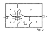
- Fig 3 shows five rooms A-E in a section of a building where a wireless telephone system according to the invention is installed.
- This section of the building is essentially covered by one base station 1.
- base station 1 For simplicity, it is here assumed that a portable 3 being carried within this section will communicate with the system via base station 1.
- another base station 1' is arranged in another section of the building, and has better signal in one of the five rooms A-E, a portable in this room will in fact communicate via this base station 1' instead.
- four beacons 4, 5, 6, 7 are shown in fig 3, arranged fixedly in rooms A, B, C and D respectively.
- each beacon 4 is arranged to regularly transmit (S1) a message, such as a proprietary code 21 (according to the DECT standard), including an identification code (ID) identifying the device and a RSSI (Radio Signal Strength Indicator) threshold value.
- a proprietary code 21 according to the DECT standard
- ID identification code
- RSSI Radio Signal Strength Indicator
- the beacon adjusts to the existing radio traffic, and uses available slots in the communication frames.
- the beacon continually informs the surroundings of its existence and transmits its identity.
- the software and/or hardware in the portable 3 listens to the proprietary code 21 transmitted from the beacons, and receives the identification code (ID) and RSSI threshold value (S2). First, the portable determines if the received signal strength exceeds the RSSI threshold included in the signal (S3). If this is not the case, the signal is deemed to have been received from too far away, thus making the received proprietary code 21 irrelevant (S4). If, however, the signal strength exceeds the threshold, the identification code (ID) is stored in the memory of the portable (S5), and represents the portable's 3 actual location.
- the portable can be adapted to store several consecutive identification codes, thereby keeping track of the position history of the portable 3, i.e. the movements of the user.
- the identification code is sent to the central unit 9 in response to a request from the system, e.g. from the central unit 9, i.e. a polling type of operation.
- a polling type of operation i.e. a polling type of operation.
- the storage of received identification codes need not be performed in the portable itself.
- the portable can be arranged to send each received to e.g. the central unit 9 via a base station 1, for storage in a memory area (not shown). This provides the ability to continually monitor the position of a portable at all times.
- no RSSI threshold is included in the transmission from the beacons. Although this makes the positioning less accurate, the system will still provide a satisfactory result in many situations. Note that portables not provided with the additional hardware and/or software implementing the invention will work as a portable in a conventional system. They will not respond to transmissions from the beacons, but on the other hand will not be disturbed by these transmissions.
Landscapes
- Engineering & Computer Science (AREA)
- Computer Networks & Wireless Communication (AREA)
- Physics & Mathematics (AREA)
- General Physics & Mathematics (AREA)
- Radar, Positioning & Navigation (AREA)
- Remote Sensing (AREA)
- Signal Processing (AREA)
- Mobile Radio Communication Systems (AREA)
Abstract
Description
- The present invention relates to a system for wireless communication in accordance with the preamble of
claim 1. Examples of such a system are described inEP-A-0 930 514 andUS-A-6 055 434 . The invention in particular relates to the field of wireless communication systems of the kind where a number of portables communicate through a number of base stations, such as in a DECT-system (Digital Enhanced Cordless Telecommunication) . - Wireless communication systems with portable devices are many times used in an environment where the ability to transmit alarms is required. Examples of such environments are prisons, care units, etc. Other examples are guards or watchmen patrolling an area such as an industry, maids in a hotel, etc.
- It is known to use an existing communication system, e.g. a DECT-system, to provide the function of alarm transmission.
- In a situation where an alarm is sent, it is normally helpful to as soon as possible find out from where this alarm was sent, in order to provide the necessary assistance. However, when using the portables of a cordless system, there is no simple way of quickly enough locating the position of the user with satisfactory accuracy. Note that the time factor and accuracy in many situations may be critical.
- Of course, this situation is only a special case of the general problem of locating a portable in a wireless communication system, such as a DECT-system.
- It is known to use the positions of the base stations in a telecommunication system to make a rough estimate of where a portable is located. This method is used e.g. in GSM networks. However, in this case the precision of the position determination is dependant on the number of base stations, making it very costly if an exact position is required (a large number of base stations).
- Other solutions include the use of infra red waves and low frequency radio waves (30-40 kHz). In short, such systems are based on the arranging of transmitters at various places in the area to be supervised. Each portable has a separate receiver for receiving this signal, thereby giving them information related to their position.
- None of these systems are however satisfactory, especially not in combination with a wireless telephone system. IR-waves require an uninterrupted path, and each portable therefore must be carried outside clothes (not in a pocket). The LF-waves on the other hand are difficult to restrict (and therefore to define a relevant position).
- An example of a related technology is given in the
British patent 2 051 444 - An object of the present invention is to provide a cost efficient way of determining the position of a user in a wireless communication system, alleviating some of the problems mentioned above.
- This and other objects are achieved with a beacon in accordance with
claim 10. The beacon is arranged to communicate according to the communication standard used by the system and to transmit a message directly receivable by portables located sufficiently close to the beacon. The message comprises an identification of said beacon. The beacon can advantageously be provided in a system of the kind mentioned by way of introduction. - The invention further provides a method for determining the position of a portable within a wireless communication system.
- A beacon is arranged to transmit a message including an identification code that is receivable by a portable. By arranging each beacon in a known, fixed position, a received identification code provides information relating to the position of the portable.
- Preferably, the beacon has the same technical properties as the portables, with the exception of being physically fixed in one position. This means they do not need to be connected to the system in the way a base station is, and are each identified by the system as any other portable. The cost for each beacon is thus significantly reduced.
- Further, each beacon can preferably be contacted via a base station, just like a portable. This allows the system to interact directly with the beacons, for example to supervise their function. This can be important in an environment where sabotage can be expected, such as in a prison.
- The identification code can be stored in the portable. At a suitable time, for example when an alarm is sent from the portable, the identification code can be transferred to the system, thereby indicating the position of the portable. It should be noted that the expression "identification code" here is used relating to the identity of the beacon, and not the portable.
- In a preferred embodiment, several consecutively received identification codes are stored by the portable. When the position of a portable is determined, the most recently stored identification code represents the portable's current location, and the preceding identification codes represent the path it has followed. This information can be used to establish in what direction the portable is being moved.
- According to another embodiment, a received identification code is transmitted to a central unit as soon as a new, not earlier received, identification code is received. There, it can be used to continually monitor the position of a portable. By logging several transmitted identification codes, the central unit can provide information about the movements of portables in the system.
- According to the invention, the identification code is only accepted (e.g. stored or transmitted) by the portable if the message is received with at least a predetermined signal strength. This ensures that the portable is at a predetermined maximum distance from the beacon, and thus makes the positioning more accurate.
- The predetermined signal strength can vary between different beacons, and in that case be included as a threshold value in the positioning message from the beacon. Upon receiving a positioning message, a portable then extracts the threshold value, and determines if the signal has a signal strength exceeding this value. Only if this is the case, the received identification code is stored by the portable.
- The possibility to set a specific required threshold value for each beacon enables the choice of active area for each device. One beacon can thus have a low required threshold value, covering a large area, such as a small building. Another beacon can have a significantly higher required threshold value, covering a smaller area, such as a particular doorway. In both cases, all portables in the covered area store the beacon's identity.
- The communication system is preferably set up according to the DECT standard. In this case, the positioning message can be a proprietary code according to the standard, and the threshold value can be a radio signal strength indicator (RSSI).
-
- Fig 1 is a schematic view of a wireless communication system in a building.
- Fig 2 is a more detailed view of a system according to an embodiment of the invention.
- Fig 3 is a plane view of a section of a building, equipped with a system according to an embodiment of the invention.
- Fig 4 is a block diagram of a method according to the invention.
- Fig 5 is a block diagram of an alarm transmission.
- The following description of a preferred embodiment of the invention is related to a wireless telephone system according to the DECT standard. Naturally, the invention can equally well be implemented by the skilled artisan in a wide variety of similar communication systems, based on other standards, such as PWT or wireless LAN.
- Fig 1 illustrates how a telephone system includes a number of
base stations 1 in a building, each connected to a Private Branch Exchange/Radio Exchange (PBX/RE) 2 via a fixed communication link, normally a hard wired link. Each base station covers asmall area 10, and these areas overlap to some extent, thereby giving adequate coverage in the entire building. A portable 3 in the building will communicate with thebase station 1 that receives the best signal strength. - Examples of principles for such communication are well known, and reference is made to the standards TBR6 "Digital Enhanced Cordless Telecomunications (DECT); General terminal attachment requirements" and TBR22 "Radio Equipment and systems (RES); Attachment requirements for terminal equipment for Digital Enhanced Cordless Telecomunications (DECT) Generic Access Profile (GAP) applications".
- Fig 2 shows in greater detail a system according to the invention, with a portable 3 and a beacon 4. The PBX/
RE 2 is also connected to a central unit 9, which can provide various functionality in the system. For example, the central unit 9 can handle alarms transmitted from the portables, and ensure that suitable measures are taken. Naturally, the PBX/RE 2 and central unit 9 can be physically integrated, and it is also possible to implement other network designs securing the same functionality. - The portable 3 can be of essentially conventional type, and comprises a
transceiver 11 for receiving and transmitting radio waves. In addition to conventional functionality, adapting the portable 3 to communicate with thebase stations 1 in accordance with the DECT standard, the portable is adapted to receive messages directly from the beacon 4, and to handle them in a way more closely described below. - The beacon 4 is arranged in a fixed location but unlike a base station has no physical connection (wire) to the PBX/RE. Instead, it can be essentially equivalent to a conventional portable. Like the portable 3, the beacon 4 is adapted to communicate with the
base stations 1 according to the DECT standard. Further, each beacon is provided with functionality for transmitting messages to nearby portables, in a way more closely described below. - Fig 3 shows five rooms A-E in a section of a building where a wireless telephone system according to the invention is installed. This section of the building is essentially covered by one
base station 1. For simplicity, it is here assumed that a portable 3 being carried within this section will communicate with the system viabase station 1. Of course, if another base station 1' is arranged in another section of the building, and has better signal in one of the five rooms A-E, a portable in this room will in fact communicate via this base station 1' instead. Further, fourbeacons - The functionality of the system will be further described in the following, with reference to fig 4 and 5.
- The hardware and/or software in each beacon 4 is arranged to regularly transmit (S1) a message, such as a proprietary code 21 (according to the DECT standard), including an identification code (ID) identifying the device and a RSSI (Radio Signal Strength Indicator) threshold value. Preferably, the beacon adjusts to the existing radio traffic, and uses available slots in the communication frames. Thus, the beacon continually informs the surroundings of its existence and transmits its identity.
- The software and/or hardware in the portable 3 listens to the
proprietary code 21 transmitted from the beacons, and receives the identification code (ID) and RSSI threshold value (S2). First, the portable determines if the received signal strength exceeds the RSSI threshold included in the signal (S3). If this is not the case, the signal is deemed to have been received from too far away, thus making the receivedproprietary code 21 irrelevant (S4). If, however, the signal strength exceeds the threshold, the identification code (ID) is stored in the memory of the portable (S5), and represents the portable's 3 actual location. The portable can be adapted to store several consecutive identification codes, thereby keeping track of the position history of the portable 3, i.e. the movements of the user. - Reference is now made to fig 5. When an
alarm 22 is sent from the portable 3, the most recently stored identification code is included in the alarm message (S6). The identification code is extracted (S7) by the central unit 9, and the location of the beacon associated with this particular identification code is identified (S8). This gives the system a fast and sufficiently correct information of the location of the portable 3. - It is also possible to include several identification codes in the alarm message, thereby giving the central unit 9 information about the movements of the user before the alarm was sent.
- Alternatively, the identification code is sent to the central unit 9 in response to a request from the system, e.g. from the central unit 9, i.e. a polling type of operation. This gives an operator or administrator the possibility to determine the location of one or
several portables 3 at any given time without requiring an active action from the portable or its user. - Of course, the storage of received identification codes need not be performed in the portable itself. Instead, the portable can be arranged to send each received to e.g. the central unit 9 via a
base station 1, for storage in a memory area (not shown). This provides the ability to continually monitor the position of a portable at all times. - In an alternative embodiment, no RSSI threshold is included in the transmission from the beacons. Although this makes the positioning less accurate, the system will still provide a satisfactory result in many situations. Note that portables not provided with the additional hardware and/or software implementing the invention will work as a portable in a conventional system. They will not respond to transmissions from the beacons, but on the other hand will not be disturbed by these transmissions.
Claims (11)
- A system for wireless communication, comprising:a plurality of base stations (1),a plurality of portable devices (3), arranged to communicate via the base stations (1) according to a communication standard,a plurality of beacons (4),wherein each beacon (4) is arranged to communicate according to said communication standard, and to transmit a message (21) directly receivable by portable devices (3) located sufficiently close to the beacon (4),
said portable devices (3) are adapted to receive said message (21),
said message comprising an identification code, identifying said beacon (4),
and wherein the portable devices (3) are adapted to store said identification code,
characterized in that said message (21) includes a threshold value, wherein the portable devices (3) are adapted to determine the signal strength of the message (21) and to store or transmit the received identification code only if the message (21) is received with a signal strength exceeding said threshold value. - A system according to claim 1, wherein said beacon is further arranged to communicate with the system via the base stations (1).
- A system according to claim 1 or 2, wherein the portable devices (3) are adapted to transmit an alarm signal, said alarm signal including the stored identification code.
- A system according to any of the preceding claims, wherein the system is a DECT (Digital Enhanced Cordless Telecommunication system.
- A system according to claim 4, wherein said message is a proprietary code as defined within the DECT standard.
- A system according to claim 1, wherein said threshold value is a RSSI (Radio Signal Strength Indicator).
- A method for determining the position of a portable device (3) in a system for wireless communication where a plurality of portable devices are arranged to communicate with each other via a plurality of base stations (1) according to a communication standard, comprising:arranging at least one beacon (4) in a fixed position,transmitting (S1) a message (21) from said beacon (4) directly to said portable devices (3) according to said communication standard, said message including an identification code,receiving (S2) said message in said portable device (3),and storing (S5) said identification code in the portable device (3), which identification code is transmitted (S6) at a suitable time,characterized in that said message (21) further includes a threshold value, usable by the portable device (3) to determine if the message (21) is received with sufficient signal strength.
- A method according to claim 7, wherein the identification code is stored in a central unit (9).
- A method according to claim 7 or 8, wherein several consecutively received and accepted identification codes are stored.
- A beacon (4) in a system for wireless communication where a plurality of portable devices (3) are arranged to communicate via a plurality of base stations (1) according to a communication standard,
wherein said beacon (4) is arranged to communicate according to said communication standard, and to transmit a message (21) directly receivable by portable devices (3) located sufficiently close to the beacon (4), said message including an identification of said beacon (4),
characterized in that said message (21) further includes a threshold value, usable by the portable device (3) to determine if the message (21) is received with sufficient signal strength. - A beacon according to claim 10, further arranged to communicate with the system via the base stations (1).
Priority Applications (3)
| Application Number | Priority Date | Filing Date | Title |
|---|---|---|---|
| EP01124500A EP1303155B1 (en) | 2001-10-12 | 2001-10-12 | System, method and device for determining the position of a portable device in a wireless communication system |
| DE60129979T DE60129979D1 (en) | 2001-10-12 | 2001-10-12 | System, method and apparatus for determining the position of a mobile station in a radio communication system |
| AT01124500T ATE370628T1 (en) | 2001-10-12 | 2001-10-12 | SYSTEM, METHOD AND DEVICE FOR DETERMINING THE POSITION OF A MOBILE STATION IN A RADIO COMMUNICATIONS SYSTEM |
Applications Claiming Priority (1)
| Application Number | Priority Date | Filing Date | Title |
|---|---|---|---|
| EP01124500A EP1303155B1 (en) | 2001-10-12 | 2001-10-12 | System, method and device for determining the position of a portable device in a wireless communication system |
Publications (2)
| Publication Number | Publication Date |
|---|---|
| EP1303155A1 EP1303155A1 (en) | 2003-04-16 |
| EP1303155B1 true EP1303155B1 (en) | 2007-08-15 |
Family
ID=8178954
Family Applications (1)
| Application Number | Title | Priority Date | Filing Date |
|---|---|---|---|
| EP01124500A Expired - Lifetime EP1303155B1 (en) | 2001-10-12 | 2001-10-12 | System, method and device for determining the position of a portable device in a wireless communication system |
Country Status (3)
| Country | Link |
|---|---|
| EP (1) | EP1303155B1 (en) |
| AT (1) | ATE370628T1 (en) |
| DE (1) | DE60129979D1 (en) |
Families Citing this family (9)
| Publication number | Priority date | Publication date | Assignee | Title |
|---|---|---|---|---|
| SE526741C2 (en) * | 2003-10-02 | 2005-11-01 | Ericsson Telefon Ab L M | Positioning of mobile stations |
| SE0302636D0 (en) * | 2003-10-02 | 2003-10-02 | Ericsson Telefon Ab L M | Positioning method for distributed antenna systems, leaking cable systems and repeater equipment |
| JP2005175656A (en) * | 2003-12-09 | 2005-06-30 | Nec Corp | Positional information acquisition system and action history recorder using it |
| US20060143090A1 (en) * | 2004-12-27 | 2006-06-29 | Barry Ridings | Method and system for identifying wireless network coverage gaps |
| FR2895198B1 (en) * | 2005-12-15 | 2008-05-09 | Sagem Comm | TELECOMMUNICATION SYSTEM FOR MOBILE TERMINALS, TAG AND TERMINAL USED IN SUCH A SYSTEM |
| FR2943163A1 (en) * | 2009-03-11 | 2010-09-17 | Cryptiris | SPATIAL LOCATION DEVICE, REFERENCE TRANSMITTER AND ASSOCIATED LOCATION SYSTEM |
| JP2014095685A (en) * | 2012-10-12 | 2014-05-22 | Ricoh Co Ltd | Distribution device, distribution method and distribution program |
| FR3041497B1 (en) * | 2015-09-17 | 2017-10-20 | Schneider Electric Ind Sas | METHOD FOR DETERMINING THE GEOGRAPHICAL POSITION OF AN EQUIPMENT |
| CN110031800B (en) * | 2019-04-28 | 2021-11-02 | 京东方科技集团股份有限公司 | Positioning method, device, computer equipment and storage medium |
Family Cites Families (2)
| Publication number | Priority date | Publication date | Assignee | Title |
|---|---|---|---|---|
| US6055434A (en) * | 1997-02-11 | 2000-04-25 | Ericsson Inc. | Method and system for locating a mobile station within a mobile telecommunications network |
| JPH11205845A (en) * | 1998-01-14 | 1999-07-30 | Locus:Kk | Position specifying system |
-
2001
- 2001-10-12 EP EP01124500A patent/EP1303155B1/en not_active Expired - Lifetime
- 2001-10-12 AT AT01124500T patent/ATE370628T1/en active
- 2001-10-12 DE DE60129979T patent/DE60129979D1/en not_active Expired - Lifetime
Non-Patent Citations (1)
| Title |
|---|
| None * |
Also Published As
| Publication number | Publication date |
|---|---|
| EP1303155A1 (en) | 2003-04-16 |
| DE60129979D1 (en) | 2007-09-27 |
| ATE370628T1 (en) | 2007-09-15 |
Similar Documents
| Publication | Publication Date | Title |
|---|---|---|
| US6032035A (en) | Emergency response system | |
| EP1671210B1 (en) | Method and system for improved wlan location | |
| EP2341359B1 (en) | Location tracking system | |
| EP0846388B1 (en) | System and method for managing subscriber unit location information in an integrated communication network | |
| US6138026A (en) | Method and apparatus for locating a wireless communication device | |
| US7315735B2 (en) | System and method for emergency 911 location detection | |
| US7127213B2 (en) | Error correlation for wireless networks | |
| CA2066864C (en) | Mobile radio communication system | |
| CA2091393C (en) | Method and apparatus for providing a personal locator, access control and asset tracking service using an in-building telephone network | |
| US6745036B1 (en) | Location beacon system | |
| US7019646B1 (en) | Combination smoke alarm and wireless location device | |
| GB2247761A (en) | Security systems | |
| CA2500659A1 (en) | Location based method and system for wireless mobile unit communication | |
| US6415155B1 (en) | Location system and method for identifying position of mobile terminal that can communicate based on repeater in radio zone, and mobile terminal that can communicate based on repeater in radio zone | |
| WO1999055102A1 (en) | Method and system for providing cellular communications services | |
| WO2003056870A1 (en) | Mobile device power saving | |
| EP1461972B1 (en) | Mobile device power saving | |
| EP1303155A1 (en) | System, method and device for determining the position of a portable device in a wireless communication system | |
| WO2000052658A1 (en) | Security network and system | |
| EP1111951A2 (en) | Wireless access systems and method of portable device location therein | |
| JPS62245393A (en) | Residence management by transponding card | |
| EP4484994A1 (en) | Indoor positioning and guidance system based on extremely low frequency magnetic field beacons and mobile devices, and associated method | |
| JP2647118B2 (en) | Wireless communication method | |
| CA2251996A1 (en) | Automatically locating individuals utilizing a combination of wireless media | |
| JPH09182137A (en) | Location registration management method for mobile communication system |
Legal Events
| Date | Code | Title | Description |
|---|---|---|---|
| PUAI | Public reference made under article 153(3) epc to a published international application that has entered the european phase |
Free format text: ORIGINAL CODE: 0009012 |
|
| AK | Designated contracting states |
Designated state(s): AT BE CH CY DE DK ES FI FR GB GR IE IT LI LU MC NL PT SE TR |
|
| AX | Request for extension of the european patent |
Extension state: AL LT LV MK RO SI |
|
| 17P | Request for examination filed |
Effective date: 20031008 |
|
| AKX | Designation fees paid |
Designated state(s): AT BE CH CY DE DK ES FI FR GB GR IE IT LI LU MC NL PT SE TR |
|
| GRAP | Despatch of communication of intention to grant a patent |
Free format text: ORIGINAL CODE: EPIDOSNIGR1 |
|
| GRAS | Grant fee paid |
Free format text: ORIGINAL CODE: EPIDOSNIGR3 |
|
| RAP1 | Party data changed (applicant data changed or rights of an application transferred) |
Owner name: ASCOM (SWEDEN) AB |
|
| GRAA | (expected) grant |
Free format text: ORIGINAL CODE: 0009210 |
|
| AK | Designated contracting states |
Kind code of ref document: B1 Designated state(s): AT BE CH CY DE DK ES FI FR GB GR IE IT LI LU MC NL PT SE TR |
|
| REG | Reference to a national code |
Ref country code: GB Ref legal event code: FG4D |
|
| REG | Reference to a national code |
Ref country code: CH Ref legal event code: EP |
|
| REG | Reference to a national code |
Ref country code: IE Ref legal event code: FG4D |
|
| REF | Corresponds to: |
Ref document number: 60129979 Country of ref document: DE Date of ref document: 20070927 Kind code of ref document: P |
|
| REG | Reference to a national code |
Ref country code: SE Ref legal event code: TRGR |
|
| ET | Fr: translation filed | ||
| PG25 | Lapsed in a contracting state [announced via postgrant information from national office to epo] |
Ref country code: FI Free format text: LAPSE BECAUSE OF FAILURE TO SUBMIT A TRANSLATION OF THE DESCRIPTION OR TO PAY THE FEE WITHIN THE PRESCRIBED TIME-LIMIT Effective date: 20070815 Ref country code: ES Free format text: LAPSE BECAUSE OF FAILURE TO SUBMIT A TRANSLATION OF THE DESCRIPTION OR TO PAY THE FEE WITHIN THE PRESCRIBED TIME-LIMIT Effective date: 20071126 |
|
| PGFP | Annual fee paid to national office [announced via postgrant information from national office to epo] |
Ref country code: DE Payment date: 20070921 Year of fee payment: 7 |
|
| PG25 | Lapsed in a contracting state [announced via postgrant information from national office to epo] |
Ref country code: DE Free format text: LAPSE BECAUSE OF FAILURE TO SUBMIT A TRANSLATION OF THE DESCRIPTION OR TO PAY THE FEE WITHIN THE PRESCRIBED TIME-LIMIT Effective date: 20071116 Ref country code: GR Free format text: LAPSE BECAUSE OF FAILURE TO SUBMIT A TRANSLATION OF THE DESCRIPTION OR TO PAY THE FEE WITHIN THE PRESCRIBED TIME-LIMIT Effective date: 20071116 Ref country code: DK Free format text: LAPSE BECAUSE OF FAILURE TO SUBMIT A TRANSLATION OF THE DESCRIPTION OR TO PAY THE FEE WITHIN THE PRESCRIBED TIME-LIMIT Effective date: 20070815 |
|
| PG25 | Lapsed in a contracting state [announced via postgrant information from national office to epo] |
Ref country code: PT Free format text: LAPSE BECAUSE OF FAILURE TO SUBMIT A TRANSLATION OF THE DESCRIPTION OR TO PAY THE FEE WITHIN THE PRESCRIBED TIME-LIMIT Effective date: 20080115 Ref country code: MC Free format text: LAPSE BECAUSE OF NON-PAYMENT OF DUE FEES Effective date: 20071031 |
|
| PLBE | No opposition filed within time limit |
Free format text: ORIGINAL CODE: 0009261 |
|
| STAA | Information on the status of an ep patent application or granted ep patent |
Free format text: STATUS: NO OPPOSITION FILED WITHIN TIME LIMIT |
|
| 26N | No opposition filed |
Effective date: 20080516 |
|
| PG25 | Lapsed in a contracting state [announced via postgrant information from national office to epo] |
Ref country code: CY Free format text: LAPSE BECAUSE OF FAILURE TO SUBMIT A TRANSLATION OF THE DESCRIPTION OR TO PAY THE FEE WITHIN THE PRESCRIBED TIME-LIMIT Effective date: 20070815 |
|
| PG25 | Lapsed in a contracting state [announced via postgrant information from national office to epo] |
Ref country code: LU Free format text: LAPSE BECAUSE OF NON-PAYMENT OF DUE FEES Effective date: 20071012 |
|
| PG25 | Lapsed in a contracting state [announced via postgrant information from national office to epo] |
Ref country code: TR Free format text: LAPSE BECAUSE OF FAILURE TO SUBMIT A TRANSLATION OF THE DESCRIPTION OR TO PAY THE FEE WITHIN THE PRESCRIBED TIME-LIMIT Effective date: 20070815 |
|
| PG25 | Lapsed in a contracting state [announced via postgrant information from national office to epo] |
Ref country code: IT Free format text: LAPSE BECAUSE OF NON-PAYMENT OF DUE FEES Effective date: 20071031 |
|
| REG | Reference to a national code |
Ref country code: FR Ref legal event code: PLFP Year of fee payment: 15 |
|
| REG | Reference to a national code |
Ref country code: FR Ref legal event code: PLFP Year of fee payment: 16 |
|
| REG | Reference to a national code |
Ref country code: FR Ref legal event code: PLFP Year of fee payment: 17 |
|
| REG | Reference to a national code |
Ref country code: FR Ref legal event code: PLFP Year of fee payment: 18 |
|
| PGFP | Annual fee paid to national office [announced via postgrant information from national office to epo] |
Ref country code: NL Payment date: 20201028 Year of fee payment: 20 |
|
| PGFP | Annual fee paid to national office [announced via postgrant information from national office to epo] |
Ref country code: FR Payment date: 20201021 Year of fee payment: 20 Ref country code: AT Payment date: 20201022 Year of fee payment: 20 Ref country code: CH Payment date: 20201021 Year of fee payment: 20 Ref country code: IE Payment date: 20201022 Year of fee payment: 20 Ref country code: SE Payment date: 20201028 Year of fee payment: 20 Ref country code: GB Payment date: 20201022 Year of fee payment: 20 |
|
| PGFP | Annual fee paid to national office [announced via postgrant information from national office to epo] |
Ref country code: BE Payment date: 20201028 Year of fee payment: 20 |
|
| REG | Reference to a national code |
Ref country code: CH Ref legal event code: PL |
|
| REG | Reference to a national code |
Ref country code: BE Ref legal event code: MK Effective date: 20211012 |
|
| REG | Reference to a national code |
Ref country code: GB Ref legal event code: PE20 Expiry date: 20211011 |
|
| REG | Reference to a national code |
Ref country code: IE Ref legal event code: MK9A |
|
| REG | Reference to a national code |
Ref country code: SE Ref legal event code: EUG |
|
| REG | Reference to a national code |
Ref country code: AT Ref legal event code: MK07 Ref document number: 370628 Country of ref document: AT Kind code of ref document: T Effective date: 20211012 |
|
| REG | Reference to a national code |
Ref country code: NL Ref legal event code: MK Effective date: 20211011 |
|
| PG25 | Lapsed in a contracting state [announced via postgrant information from national office to epo] |
Ref country code: IE Free format text: LAPSE BECAUSE OF EXPIRATION OF PROTECTION Effective date: 20211012 Ref country code: GB Free format text: LAPSE BECAUSE OF EXPIRATION OF PROTECTION Effective date: 20211011 |