EP1303049A1 - Decoding apparatus, decoding method, lookup table, and decoding program - Google Patents
Decoding apparatus, decoding method, lookup table, and decoding program Download PDFInfo
- Publication number
- EP1303049A1 EP1303049A1 EP02730799A EP02730799A EP1303049A1 EP 1303049 A1 EP1303049 A1 EP 1303049A1 EP 02730799 A EP02730799 A EP 02730799A EP 02730799 A EP02730799 A EP 02730799A EP 1303049 A1 EP1303049 A1 EP 1303049A1
- Authority
- EP
- European Patent Office
- Prior art keywords
- bit sequence
- symbol
- sequence
- code length
- length
- Prior art date
- Legal status (The legal status is an assumption and is not a legal conclusion. Google has not performed a legal analysis and makes no representation as to the accuracy of the status listed.)
- Withdrawn
Links
Images



Classifications
-
- H—ELECTRICITY
- H03—ELECTRONIC CIRCUITRY
- H03M—CODING; DECODING; CODE CONVERSION IN GENERAL
- H03M7/00—Conversion of a code where information is represented by a given sequence or number of digits to a code where the same, similar or subset of information is represented by a different sequence or number of digits
- H03M7/30—Compression; Expansion; Suppression of unnecessary data, e.g. redundancy reduction
- H03M7/40—Conversion to or from variable length codes, e.g. Shannon-Fano code, Huffman code, Morse code
-
- H—ELECTRICITY
- H03—ELECTRONIC CIRCUITRY
- H03M—CODING; DECODING; CODE CONVERSION IN GENERAL
- H03M7/00—Conversion of a code where information is represented by a given sequence or number of digits to a code where the same, similar or subset of information is represented by a different sequence or number of digits
- H03M7/30—Compression; Expansion; Suppression of unnecessary data, e.g. redundancy reduction
- H03M7/40—Conversion to or from variable length codes, e.g. Shannon-Fano code, Huffman code, Morse code
- H03M7/42—Conversion to or from variable length codes, e.g. Shannon-Fano code, Huffman code, Morse code using table look-up for the coding or decoding process, e.g. using read-only memory
- H03M7/425—Conversion to or from variable length codes, e.g. Shannon-Fano code, Huffman code, Morse code using table look-up for the coding or decoding process, e.g. using read-only memory for the decoding process only
Definitions
- the present invention relates to a decoder, a decoding method, a look-up table, and a decoding program. Inparticular, the present invention is suitably applied to decode a variable length code.
- Figure 8 is a diagram showing the configuration of such a conventional look-up table.
- a code table 11 is defined in which, for example, a code bit "1" is assigned to a symbol S0, code bits "01” are assigned to a symbol S1, code bits "001” are assigned to a symbol S2, and code bits "000” are assigned to a symbol S3.
- sequence numbers since the maximum code length of the code bits is 3, sequence numbers, the symbols and code lengths are registered in a look-up table 12 with respect to 2 3 entries identified by 3-bit bit sequences, as shown in Figure 8(b).
- the sequence numbers may be numbers in decimal notation corresponding to the 3-bit bit sequences.
- Bits are read in groups of three bits from the input bit sequence. Each read group of three bits is converted into a decimal number to obtain the sequence number. When the sequence number is obtained, the look-up table 12 is referred to with the sequence number used as a key to obtain the symbol corresponding to the sequence number. The symbol is output as a decoding result while the bit(s) remaining as a result of subtraction of the bits corresponding to the code length of the symbol from bit sequences for 3-bit is returned to the input bit sequence.
- the input bit sequence is "1010010110 ⁇ "
- the first three bits "101" of this bit sequence is read and this "101" is converted into a decimal number to obtain a sequence number "5".
- the look-up table 12 shown in Figure 8(b) is referred to with this sequence number "5" used as a key to obtain the symbol "S0” and the code length "1" of the symbol "S0".
- the symbol "S0" is output as a decoding result.
- the code length "1" of the symbol “S0” is compared with the maximum code length "3". Two bits “01” corresponding to the difference between the maximum code length "3” and the code length "1” of the symbol “S0” are considered unused in decoding of the symbol "S0" and are returned to the input bit sequence "0010110 ⁇ ".
- decoding can be performed only by reading one time the bit sequence corresponding to the maximum code length from the input bit sequence and, consequently, the speed of decoding can be increased.
- the maximum code length is larger, the number of times one symbol is duplicated when the symbol is registered is increased, resulting in an increase in capacity of the look-up table. For example, if the maximum code length is 16 and if 100 bytes per symbol and one byte for storage of the code length are needed, a capacity of 2 16 ⁇ 101 bytes is required.
- an object of the present invention to provide a decoder, a decoding method, a look-up table, and a decoding program enabling decoding at a higher speed with a small storage capacity.
- a decoder provided to attain the above-described object according to the present invention is characterized by comprising symbol association means for associating each of reference places for encoded symbols with one of the symbols, and reference place identification means for identifying the reference place for each of symbols when the bit sequence assigned to the symbol and corresponding to the maximum code length is cut out.
- each encoded symbol can be identified when the corresponding bit sequence is cut out, and it is possible to reduce the storage capacity while maintaining high-speed decoding performance.
- a decoder is characterized by comprising reference place information acquisition means for obtaining, on the basis of a bit sequence of a predetermined length, reference place information for a decoding result corresponding to a code contained in the bit sequence, and decoding result acquisition means for obtaining, on the basis of the reference place information obtained by the reference place information acquisition means, the decoding result corresponding to the code contained in the bit sequence.
- a decoder which decodes each of encoded symbols, is characterized by comprising an input buffer which reads from an input bit sequence a bit sequence having a length corresponding to the maximum code length of the symbols, a first sequence table in which reference place information for the symbols is registered with respect to each bit sequence having a length corresponding to the maximum code length of the symbols, a second sequence table in which the symbol and the code length of the symbol are registered with respect to each symbol, first reference means for obtaining the reference place information for the symbol corresponding to a code contained in the bit sequence read to the input buffer by referring to the first sequence table on the basis of the bit sequence, second reference means for obtaining the symbol corresponding to the code contained in the bit sequence and the code length of the symbol by referring to the second sequence table on the basis of the reference place information obtained by the first reference means, and return means for returning to the input bit sequence the remaining bit excluding the bit corresponding to the code length of the symbol from the bit sequence read to the input buffer.
- each symbol and the code length of the symbol can be obtained from the second sequence table if only reference places for the symbols are registered in the first sequence table by being associated with the bit sequences having a length corresponding to the maximum code length.
- decoding of the variable length code can be performed by making access two times to the first sequence table and the second sequence table. Also, the need for registering each of the symbols and the code lengths of the symbols in a state of being duplicated a certain number of times by being associated with the bit sequences having a length corresponding to the maximum code length is eliminated, thereby reducing the storage capacity while maintaining high-speed decoding performance.
- a decoder which decodes each of encoded symbols, is characterized by comprising an input buffer which reads from an input bit sequence a bit sequence having a length corresponding to the maximum code length of the symbols, a first sequence table in which reference place information for the symbols is registered with respect to each bit sequence having a length corresponding to the maximum code length of the symbols, a second sequence table in which the symbol and the difference of the code length of the symbol from the maximum code length are registered with respect to each symbol, first reference means for obtaining the reference place information for the symbol corresponding to a code contained in the bit sequence read to the input buffer by referring to the first sequence table on the basis of the bit sequence, second reference means for obtaining the symbol corresponding to the code contained in the bit sequence and the difference by referring to the second sequence table on the basis of the reference place information obtained by the first reference means, and return means for returning to the input bit sequence the bit sequence read to the input buffer by the amount corresponding to the difference.
- each symbol and the difference of the code length of the symbol from the maximum code length can be obtained from the second sequence table if only reference places for the symbols are registered in the first sequence table by being associated with the bit sequences having a length corresponding to the maximum code length.
- decoding of the variable length code can be performed by making access two times to the first sequence table and the second sequence table. Also, the number of bits not used in decoding of the variable length code can be obtained directly from the second sequence table, thereby reducing the number of access times, eliminating subtraction processing performed for return of a bit sequence, and further increasing the decoding speed.
- the decoder is characterized in that the first sequence table is divided into a plurality of tables in correspondence with an upper bit sequence and a lower bit sequence having a length corresponding to the maximum code length.
- the number of sequences for identification of entries can be reduced thereby to further reduce the storage capacity.
- a decoding method is characterized by comprising a step of reading from an input bit sequence a bit sequence having a length corresponding to the maximum code length, a step of obtaining, on the basis of the read bit sequence, reference place information for a symbol corresponding to a code contained in the bit sequence, a step of obtaining, from the obtained reference place information, the symbol corresponding to the code contained in the bit sequence and the code length of the symbol, a step of outputting the obtained symbol as a result of decoding of the code contained in the read bit sequence, and a step of returning to the input bit sequence the bit remaining bit as excluding the bit corresponding to the code length of the symbol from the read bit sequence.
- a look-up table according to the present invention is characterized by comprising a first sequence table in which reference place information for symbols is registered with respect to each of candidates for codes to be decoded, and a second sequence table in which the symbol and the code length of the symbol are registered with respect to each symbol.
- a look-up table is characterized in that symbols and the differences of the code lengths of the symbols from the maximum code length are registered with respect to entries identified by bit sequences having a length corresponding to the maximum code length of the symbols.
- each decoded symbol can be output by only making access to the look-up table one time and the number of bits not used in decoding of the symbol can also be obtained thereby.
- a decoding program is characterized by executing with a computer a step of reading from an input bit sequence a bit sequence having a length corresponding to the maximum code length, a step of obtaining, on the basis of the read bit sequence, reference place information for a symbol corresponding to a code contained in the bit sequence, a step of obtaining, from the obtained reference place information, the symbol corresponding to the code contained in the bit sequence and the code length of the symbol, a step of outputting the obtained symbol as a result of decoding of the code contained in the read bit sequence, and a step of returning to the input bit sequence the remaining bit excluding the bit corresponding to the code length of the symbol from the read bit sequence.
- the speed of decoding of the variable length code can be increased and the storage capacity of the loop-up table can be reduced.
- a decoding program is characterized by executingwith a computer a step of reading from an input bit sequence a bit sequence having a length corresponding to the maximum code length, a step of obtaining, on the basis of the read bit sequence, reference place information for a symbol corresponding to a code contained in the bit sequence, a step of obtaining, from the obtained reference place information, the symbol corresponding to the code contained in the bit sequence and the difference of the code length of the symbol from the maximum code length, a step of outputting the obtained symbol as a result of decoding of the code contained in the read bit sequence, and a step of returning to the input bit sequence the read bit sequence by the amount corresponding to the difference.
- this decoding program is installed, the number of bits not used in decoding of each symbol can be directly obtained, subtraction processing performed for return of a bit sequence can be eliminated and the decoding speed can be further increased.
- Figure 1 is a block diagram schematically showing a configuration of a decoder according to a first embodiment of the present invention.
- the decoder has symbol association means 101 and reference place identification means 102.
- the symbol association means 101 associates each of reference places for encoded symbols with one of the symbols.
- the reference place identification means 102 cuts out, from an input bit sequence, each of bit sequences assigned to symbols with a length corresponding to the maximum code length, and identifies the reference place for the symbol with respect to each bit sequence cut out.
- the reference place identification means 102 outputs the symbol corresponding to the identified reference place by referring to the symbol association means 101.
- each encoded symbol can be identified when the corresponding bit sequence is cut out, and it is possible to reduce the storage capacity while maintaining high-speed decoding performance.
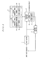
- Figure 2 is a block diagram showing a configuration of a decoder according to a second embodiment of the present invention.
- an input buffer 1 reads a bit sequence corresponding to the maximum code length of symbols SY from an input bit sequence.
- a reference section 2 refers to a first sequence table 3a by using as a key a sequence number LN determined by the bit sequence read by the input buffer 1 to obtain an index (reference place) IN for the symbol SY corresponding to a code contained in the bit sequence. Further, the reference section 2 refers to a second sequence table 3b by using the index IN as a key to obtain the symbol SY corresponding to the code contained in the bit sequence read to the input buffer 1 and the code length LC of the symbol SY.
- a look-up table 3 has the first sequence table 3a and the second sequence table 3b.
- the index IN for each symbol SY to be obtained as a decoding result is registered in correspondence with the sequence number LN determined by the bit sequence having the length corresponding to the maximum code length of symbols SY.
- the symbol SY to be obtained as a decoding result and the code length LC of the symbol are registered in correspondence with the index IN.
- a return section 4 returns to the input bit sequence the remaining bit(s) excluding the bit corresponding to the code length LC of the symbol SY from the corresponding bit sequence read to the input buffer 1.
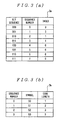
- Figure 3 is a diagram showing an example of a configuration of a look-up table 3 according to the second embodiment of the present invention. It is assumed here that a code bit "1" is assigned to symbol S0, code bits "01” are assigned to symbol S1, code bits "001” are assigned to symbol S2, and code bits "000” are assigned to symbol S3, as shown in Figure 8(a).
- sequence number LN and the index IN associated with a particular entry identified by each of 3-bit bit sequences are registered in the first sequence table 3a, as shown in Figure 3(a).
- the sequence numbers LN may be numbers in decimal notation corresponding to the 3-bit bit sequences.
- the reference section 2 converts the three bits into a decimal number to obtain the sequence number LN.
- the reference section 2 refers to the first sequence table 3a by using the sequence number LN as a key to obtain the index IN corresponding to the sequence number LN.
- the reference section 2 refers to the second sequence table 3b by using the index IN as a key to obtain the symbol SY corresponding to the index IN and the code length LL of the symbol SY, outputs the symbol SY as a decoding result, and outputs the code length LL to the return section 4.
- the return section 4 receives the code length LL from the reference section 2 and computes the difference between the maximum code length and the code length LL received from the reference section 2. The return section 4 then returns to the input bit sequence the following part of the 3-bit bit sequence read to the input buffer 1 which part corresponds to the number of bits obtained as the difference.
- indices IN are registered instead of symbols SY and the code lengths LC of the symbols by being associated with sequence numbers LN, thereby enabling access from each sequence number LN to the symbol SY if each of the symbols SY and the code lengths LC of the symbols is held only one time.
- the need for holding each of the symbols SY and the code lengths LC of the symbols in a state of being duplicated a certain number of times is eliminated.
- indices IN are registered by being associated with sequence numbers LN, it is necessary to hold each index IN in a state of being duplicated a certain number of times.
- each index IN can be set simply as a number (numeric character) and can therefore be expressed by a smaller number of bits in comparison with symbol SY which may contain a letter or a symbol as well as a numeric character. Therefore the storage capacity can be reduced in comparison with the case where symbols SY and the code lengths LC of the symbols are registered by being associated with sequence numbers LN.
- decoding of the variable length code can be performed by making access two times to the first sequence table 3a and the second sequence table 3b, thus maintaining high-speed decoding performance.
- symbols SY with a higher frequency of occurrence and the code lengths LC of the symbols may be held on a cache to reduce the access time and to thereby improve the decoding speed.
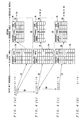
- Figure 4 is a diagram showing a decoding method according to an embodiment of the present invention.
- the input buffer 1 reads the first group of three bits "101" from the input bit sequence and outputs these bits to the reference section 2.
- the reference section 2 receives the bit sequence "101" and converts the same into a decimal number to obtain the sequence number "5".
- the reference section 2 refers to the sequence table 3a by using the sequence number "5" as a key to obtain the index "0" ((1)).
- the reference section 2 After obtaining the index "0", the reference section 2 refers to the sequence table 3b by using the index "0" as a key to obtain the symbol "S0" and the code length "1" of the symbol “S0” ((2)), outputs the symbol “S0” as a decoding result ((3)), and outputs the code length "1" of the symbol “S0” to the return section 4 ((4)).
- the input buffer 1 reads three bits "010” from the input bit sequence "010010110 ⁇ " after return, as shown in Figure 4(b), and outputs these bits to the reference section 2.
- the reference section 2 receives the bit sequence "010” and converts the same into a decimal number to obtain the sequence number "2".
- the reference section 2 refers to the sequence table 3a by using the sequence number "2" as a key to obtain the index "1" ((6)).
- the reference section 2 refers to the sequence table 3b by using the index "1" as a key to obtain the symbol “S1" and the code length “2" of the symbol “S1” ((7)), outputs the symbol “S1” as a decoding result ((8)), and outputs the code length "2" of the symbol “S1” to the return section 4 ((9)).
- the input buffer 1 reads three bits "001" from the input bit sequence "0010110 ⁇ " after return, as shown in Figure 4(c), and outputs these bits to the reference section 2.
- the reference section 2 receives the bit sequence "001” and converts the same into a decimal number to obtain the sequence number "1".
- the reference section 2 refers to the sequence table 3a by using the sequence number "1" as a key to obtain the index "2" ((11)).
- the reference section 2 refers to the sequence table 3b by using the index "2" as a key to obtain the symbol “S2" and the code length "3" of the symbol “S2” ((12)), outputs the symbol “S2” as a decoding result ((13)), and outputs the code length "3" of the symbol “S2” to the return section 4.
- Figure 5 is a flowchart showing the decoding method according to an embodiment of the present invention.
- step S1 if an undecoded input bit sequence exits (step S1), a bit sequence having a length corresponding to the maximum code length is read from the input bit sequence (step S2).
- the sequence number LN is computed from the read bit sequence (step S3), and the first sequence table 3a is referred to by using the sequence number LN as a key to obtain the index IN (step S4).
- the second sequence table 3b is referred to by using the index IN as a key to obtain the corresponding symbol SY and the code length LC of the symbol (step S5), and the symbol SY is output as a decoding result (step S6).
- step S7 From the bit sequence read in step S2, the remaining bit(s) (or bit sequence) excluding the bit corresponding to the code length LC of the symbol SY isreturned to the undecoded input bit sequence (step S7).
- the first sequence table 3a may be divided into aplurality of tables. The number of sequences necessary for identifying the index IN can be reduced thereby to further reduce the storage capacity.
- Figure 6 is a diagram showing an example of a configuration of a look-up table according to a third embodiment of the present invention.
- a code table shown in Figure 6(b) is obtained by dividing the code bits shown in Figure 6(a) into upper three bits and lower six bits.
- the code can be determined as symbol S4.
- the code can be determined as symbol S4, the symbol can be determined by further reading the six bits and referring to the table 000 .
- the code can be determined as symbol S4, the symbol can be determined by further reading the six bits and referring to the table 001 .
- the table 000 is a table prepared with respect to the symbols having "000” as the upper three bits and having the upper three bits removed in the symbols S0 to S19 defined in Figure 6(a)
- the table 001 is a table prepared with respect to the symbols having "001" as the upper three bits and having the upper three bits removed in the symbols S0 to S19 defined in Figure 6(a).
- Figure 7 is a diagram showing an example of a configuration of a look-up table 12' according to a fourth embodiment of the present invention.
- the differences of the code lengths registered in a look-up table 12 shown in Figure 8(b) from the maximum code length are registered instead of the code lengths.
- code bits corresponding to symbols S0 to S3 are defined as shown in a code table 11 of Figure 8(a).
- the maximum code length of the code bits is 3
- the sequence numbers, the symbols and the differences of the code lengths of the symbols from the maximum code length are registered in the look-up table 12' with respect to 2 3 entries identified by 3-bit sequences, as shown in Figure 7.
- symbols and entries identified by bit sequences having a length corresponding to the maximum code length can be associated with each other while avoiding registration of each symbol in a duplicated state, thereby reducing the storage capacity while maintaining high-speed decoding performance.
Landscapes
- Engineering & Computer Science (AREA)
- Theoretical Computer Science (AREA)
- Compression, Expansion, Code Conversion, And Decoders (AREA)
- Compression Or Coding Systems Of Tv Signals (AREA)
Abstract
There is provided symbol association means 101 for
associating each of reference places for encoded symbols with
one of the symbols. Reference place identification means 102
cuts out, from an input bit sequence, each of bit sequences
assigned to the symbols with a length corresponding to amaximum
code length, identifies the reference place for the symbol
with respect to each bit sequence cut out, and outputs the
symbol corresponding to the identified reference place by
referring to the symbol association means 101.
Description
The present invention relates to a decoder, a decoding
method, a look-up table, and a decoding program. Inparticular,
the present invention is suitably applied to decode a variable
length code.
There is a conventional method of decoding a variable
length code in such a manner that a code bit is read bit by
bit from an input bit sequence and symbol corresponding to
a bit sequence defined in a code table is output as a decoding
result when a match occurs between the read bits and the bit
sequence. According to this method, decoding can be performed
by using a small storage capacity if only code bits
corresponding to symbols are held. However, the time required
for decoding is long because of one-bit-by-one-bit reading
of code bits from the input bit sequence.
On the other hand, there is a method in which, to perform
high-speed decoding, symbols from which a decoding result is
obtained and the code lengths of the symbols are registered
in a look-up table with respect to all entries (candidates)
identified by bit sequences corresponding to maximum code
lengths.
Figure 8 is a diagram showing the configuration of such
a conventional look-up table.
Referring to Figure 8(a), a code table 11 is defined in
which, for example, a code bit "1" is assigned to a symbol
S0, code bits "01" are assigned to a symbol S1, code bits "001"
are assigned to a symbol S2, and code bits "000" are assigned
to a symbol S3.
In this case, since the maximum code length of the code
bits is 3, sequence numbers, the symbols and code lengths are
registered in a look-up table 12 with respect to 23 entries
identified by 3-bit bit sequences, as shown in Figure 8(b).
The sequence numbers may be numbers in decimal notation
corresponding to the 3-bit bit sequences.
Bits are read in groups of three bits from the input bit
sequence. Each read group of three bits is converted into
a decimal number to obtain the sequence number. When the
sequence number is obtained, the look-up table 12 is referred
to with the sequence number used as a key to obtain the symbol
corresponding to the sequence number. The symbol is output
as a decoding result while the bit(s) remaining as a result
of subtraction of the bits corresponding to the code length
of the symbol from bit sequences for 3-bit is returned to the
input bit sequence.
For example, if the input bit sequence is "1010010110
···", the first three bits "101" of this bit sequence is read
and this "101" is converted into a decimal number to obtain
a sequence number "5". The look-up table 12 shown in Figure
8(b) is referred to with this sequence number "5" used as a
key to obtain the symbol "S0" and the code length "1" of the
symbol "S0". The symbol "S0" is output as a decoding result.
Also, the code length "1" of the symbol "S0" is compared
with the maximum code length "3". Two bits "01" corresponding
to the difference between the maximum code length "3" and the
code length "1" of the symbol "S0" are considered unused in
decoding of the symbol "S0" and are returned to the input bit
sequence "0010110 ···".
Subsequently, the next three bits "010" are read from
the input bit sequence "010010110 ···" to which the bits have
been returned, and the above-described processing is repeated.
According to the above-described conventional method,
decoding can be performed only by reading one time the bit
sequence corresponding to the maximum code length from the
input bit sequence and, consequently, the speed of decoding
can be increased.
The above-described conventional method, however,
requires registering symbols and the code lengths of the
symbols with respect to all entries identified by bit sequences
corresponding to the maximum code length and therefore has
the problem that the capacity of look-up table 12 is increased.
That is, in the example shown in Figure 8, there are only
four symbols but it is necessary to register 23 entries of
the symbols and the code lengths of the symbols and, therefore,
the same symbol is registered in a state of being duplicated
a certain number of times.
In particular, if the maximum code length is larger, the
number of times one symbol is duplicated when the symbol is
registered is increased, resulting in an increase in capacity
of the look-up table. For example, if the maximum code length
is 16 and if 100 bytes per symbol and one byte for storage
of the code length are needed, a capacity of 216 × 101 bytes
is required.
It is, therefore, an object of the present invention to
provide a decoder, a decoding method, a look-up table, and
a decoding program enabling decoding at a higher speed with
a small storage capacity.
A decoder provided to attain the above-described object
according to the present invention is characterized by
comprising symbol association means for associating each of
reference places for encoded symbols with one of the symbols,
and reference place identification means for identifying the
reference place for each of symbols when the bit sequence
assigned to the symbol and corresponding to the maximum code
length is cut out.
It is thereby ensured that while the symbols are not
registered in correspondence with all entries identified by
the bit sequences corresponding to the maximum code length,
each encoded symbol can be identified when the corresponding
bit sequence is cut out, and it is possible to reduce the storage
capacity while maintaining high-speed decoding performance.
A decoder according to another aspect of the present
invention is characterized by comprising reference place
information acquisition means for obtaining, on the basis of
a bit sequence of a predetermined length, reference place
information for a decoding result corresponding to a code
contained in the bit sequence, and decoding result acquisition
means for obtaining, on the basis of the reference place
information obtained by the reference place information
acquisition means, the decoding result corresponding to the
code contained in the bit sequence.
It is thereby ensured that symbols and entries identified
by bit sequences having a predetermined length can be
associated with each other while avoiding registration of each
symbol to be obtained as a decoding result in a duplicated
state, thereby reducing the storage capacitywhile maintaining
high-speed decoding performance.
A decoder according to still another aspect of the present
invention, which decodes each of encoded symbols, is
characterized by comprising an input buffer which reads from
an input bit sequence a bit sequence having a length
corresponding to the maximum code length of the symbols, a
first sequence table in which reference place information for
the symbols is registered with respect to each bit sequence
having a length corresponding to the maximum code length of
the symbols, a second sequence table in which the symbol and
the code length of the symbol are registered with respect to
each symbol, first reference means for obtaining the reference
place information for the symbol corresponding to a code
contained in the bit sequence read to the input buffer by
referring to the first sequence table on the basis of the bit
sequence, second reference means for obtaining the symbol
corresponding to the code contained in the bit sequence and
the code length of the symbol by referring to the second sequence
table on the basis of the reference place information obtained
by the first reference means, and return means for returning
to the input bit sequence the remaining bit excluding the bit
corresponding to the code length of the symbol from the bit
sequence read to the input buffer.
It is thereby ensured that each symbol and the code length
of the symbol can be obtained from the second sequence table
if only reference places for the symbols are registered in
the first sequence table by being associated with the bit
sequences having a length corresponding to the maximum code
length.
Therefore decoding of the variable length code can be
performed by making access two times to the first sequence
table and the second sequence table. Also, the need for
registering each of the symbols and the code lengths of the
symbols in a state of being duplicated a certain number of
times by being associated with the bit sequences having a length
corresponding to the maximum code length is eliminated, thereby
reducing the storage capacity while maintaining high-speed
decoding performance.
A decoder according to still another aspect of the present
invention, which decodes each of encoded symbols, is
characterized by comprising an input buffer which reads from
an input bit sequence a bit sequence having a length
corresponding to the maximum code length of the symbols, a
first sequence table in which reference place information for
the symbols is registered with respect to each bit sequence
having a length corresponding to the maximum code length of
the symbols, a second sequence table in which the symbol and
the difference of the code length of the symbol from the maximum
code length are registered with respect to each symbol, first
reference means for obtaining the reference place information
for the symbol corresponding to a code contained in the bit
sequence read to the input buffer by referring to the first
sequence table on the basis of the bit sequence, second
reference means for obtaining the symbol corresponding to the
code contained in the bit sequence and the difference by
referring to the second sequence table on the basis of the
reference place information obtained by the first reference
means, and return means for returning to the input bit sequence
the bit sequence read to the input buffer by the amount
corresponding to the difference.
It is thereby ensured that each symbol and the difference
of the code length of the symbol from the maximum code length
can be obtained from the second sequence table if only reference
places for the symbols are registered in the first sequence
table by being associated with the bit sequences having a length
corresponding to the maximum code length.
Therefore decoding of the variable length code can be
performed by making access two times to the first sequence
table and the second sequence table. Also, the number of bits
not used in decoding of the variable length code can be obtained
directly from the second sequence table, thereby reducing the
number of access times, eliminating subtraction processing
performed for return of a bit sequence, and further increasing
the decoding speed.
According to still another aspect of the present invention,
the decoder is characterized in that the first sequence table
is divided into a plurality of tables in correspondence with
an upper bit sequence and a lower bit sequence having a length
corresponding to the maximum code length.
The number of sequences for identification of entries
can be reduced thereby to further reduce the storage capacity.
A decoding method according to the present invention is
characterized by comprising a step of reading from an input
bit sequence a bit sequence having a length corresponding to
the maximum code length, a step of obtaining, on the basis
of the read bit sequence, reference place information for a
symbol corresponding to a code contained in the bit sequence,
a step of obtaining, from the obtained reference place
information, the symbol corresponding to the code contained
in the bit sequence and the code length of the symbol, a step
of outputting the obtained symbol as a result of decoding of
the code contained in the read bit sequence, and a step of
returning to the input bit sequence the bit remaining bit as
excluding the bit corresponding to the code length of the symbol
from the read bit sequence.
It is thereby ensured that, even for decoding of the
variable length code by reading of a length corresponding to
the maximum code length, registration of only reference places
for symbols associated with bit sequences having a length
corresponding to the maximum code length is enough and there
is no need to register the same symbol and the code length
of the symbol in a state of being duplicated a certain number
of times, thus reducing the storage capacity while maintaining
high-speed decoding performance.
A look-up table according to the present invention is
characterized by comprising a first sequence table in which
reference place information for symbols is registered with
respect to each of candidates for codes to be decoded, and
a second sequence table in which the symbol and the code length
of the symbol are registered with respect to each symbol.
It is thereby ensured that access to the symbol
corresponding to each of candidates of the codes to be decoded
can be made by only referring to the first sequence table one
time, and the need for registration of the symbol with respect
to each candidate is eliminated, thus improving the decoding
speed while limiting the increase in storage capacity.
A look-up table according to another aspect of the present
invention is characterized in that symbols and the differences
of the code lengths of the symbols from the maximum code length
are registered with respect to entries identified by bit
sequences having a length corresponding to the maximum code
length of the symbols.
It is thereby ensured that each decoded symbol can be
output by only making access to the look-up table one time
and the number of bits not used in decoding of the symbol can
also be obtained thereby. Thus, it is possible to eliminate
subtraction processing performed for return of the bit sequence
to further increase the decoding speed.
A decoding program according to the present invention,
is characterized by executing with a computer a step of reading
from an input bit sequence a bit sequence having a length
corresponding to the maximum code length, a step of obtaining,
on the basis of the read bit sequence, reference place
information for a symbol corresponding to a code contained
in the bit sequence, a step of obtaining, from the obtained
reference place information, the symbol corresponding to the
code contained in the bit sequence and the code length of the
symbol, a step of outputting the obtained symbol as a result
of decoding of the code contained in the read bit sequence,
and a step of returning to the input bit sequence the remaining
bit excluding the bit corresponding to the code length of the
symbol from the read bit sequence.
If this decoding program is installed, the speed of
decoding of the variable length code can be increased and the
storage capacity of the loop-up table can be reduced.
A decoding program according to another aspect of the
present invention is characterized by executingwith a computer
a step of reading from an input bit sequence a bit sequence
having a length corresponding to the maximum code length, a
step of obtaining, on the basis of the read bit sequence,
reference place information for a symbol corresponding to a
code contained in the bit sequence, a step of obtaining, from
the obtained reference place information, the symbol
corresponding to the code contained in the bit sequence and
the difference of the code length of the symbol from the maximum
code length, a step of outputting the obtained symbol as a
result of decoding of the code contained in the read bit sequence,
and a step of returning to the input bit sequence the read
bit sequence by the amount corresponding to the difference.
If this decoding program is installed, the number of bits
not used in decoding of each symbol can be directly obtained,
subtraction processing performed for return of a bit sequence
can be eliminated and the decoding speed can be further
increased.
A decoder and a decoding method according to an embodiment
of the present invention will be described with reference to
the drawings.
Figure 1 is a block diagram schematically showing a
configuration of a decoder according to a first embodiment
of the present invention.
Referring to Figure 1, the decoder has symbol association
means 101 and reference place identification means 102.
The symbol association means 101 associates each of
reference places for encoded symbols with one of the symbols.
The reference place identification means 102 cuts out, from
an input bit sequence, each of bit sequences assigned to symbols
with a length corresponding to the maximum code length, and
identifies the reference place for the symbol with respect
to each bit sequence cut out. The reference place
identification means 102 outputs the symbol corresponding to
the identified reference place by referring to the symbol
association means 101.
Thus, while the symbols are not registered in
correspondence with all entries identifiedby the bit sequences
corresponding to the maximum code length, each encoded symbol
can be identified when the corresponding bit sequence is cut
out, and it is possible to reduce the storage capacity while
maintaining high-speed decoding performance.
Figure 2 is a block diagram showing a configuration of
a decoder according to a second embodiment of the present
invention.
Referring to Figure 2, an input buffer 1 reads a bit
sequence corresponding to the maximum code length of symbols
SY from an input bit sequence. A reference section 2 refers
to a first sequence table 3a by using as a key a sequence number
LN determined by the bit sequence read by the input buffer
1 to obtain an index (reference place) IN for the symbol SY
corresponding to a code contained in the bit sequence. Further,
the reference section 2 refers to a second sequence table 3b
by using the index IN as a key to obtain the symbol SY
corresponding to the code contained in the bit sequence read
to the input buffer 1 and the code length LC of the symbol
SY.
A look-up table 3 has the first sequence table 3a and
the second sequence table 3b. In the first sequence table
3a, the index IN for each symbol SY to be obtained as a decoding
result is registered in correspondence with the sequence number
LN determined by the bit sequence having the length
corresponding to the maximum code length of symbols SY. In
the second sequence table 3b, the symbol SY to be obtained
as a decoding result and the code length LC of the symbol are
registered in correspondence with the index IN.
A return section 4 returns to the input bit sequence the
remaining bit(s) excluding the bit corresponding to the code
length LC of the symbol SY from the corresponding bit sequence
read to the input buffer 1.
Figure 3 is a diagram showing an example of a configuration
of a look-up table 3 according to the second embodiment of
the present invention. It is assumed here that a code bit
"1" is assigned to symbol S0, code bits "01" are assigned to
symbol S1, code bits "001" are assigned to symbol S2, and code
bits "000" are assigned to symbol S3, as shown in Figure 8(a).
In this case, since the maximum code length of these code
bits is 3, the sequence number LN and the index IN associated
with a particular entry identified by each of 3-bit bit
sequences are registered in the first sequence table 3a, as
shown in Figure 3(a). The sequence numbers LN may be numbers
in decimal notation corresponding to the 3-bit bit sequences.
On the other hand, in the second sequence table 3b, the
symbol SY and the code length LC associated with the sequence
number determined by each index IN are registered, as shown
in Figure 3(b).
As the input buffer 1 reads bit sequences in groups of
three bits from an input bit sequence, the reference section
2 converts the three bits into a decimal number to obtain the
sequence number LN. After obtaining the sequence number LN,
the reference section 2 refers to the first sequence table
3a by using the sequence number LN as a key to obtain the index
IN corresponding to the sequence number LN. After obtaining
the index IN, the reference section 2 refers to the second
sequence table 3b by using the index IN as a key to obtain
the symbol SY corresponding to the index IN and the code length
LL of the symbol SY, outputs the symbol SY as a decoding result,
and outputs the code length LL to the return section 4.
The return section 4 receives the code length LL from
the reference section 2 and computes the difference between
the maximum code length and the code length LL received from
the reference section 2. The return section 4 then returns
to the input bit sequence the following part of the 3-bit bit
sequence read to the input buffer 1 which part corresponds
to the number of bits obtained as the difference.
Thus, indices IN are registered instead of symbols SY
and the code lengths LC of the symbols by being associated
with sequence numbers LN, thereby enabling access from each
sequence number LN to the symbol SY if each of the symbols
SY and the code lengths LC of the symbols is held only one
time. Thus, the need for holding each of the symbols SY and
the code lengths LC of the symbols in a state of being duplicated
a certain number of times is eliminated. In the case where
indices IN are registered by being associated with sequence
numbers LN, it is necessary to hold each index IN in a state
of being duplicated a certain number of times. However, each
index IN can be set simply as a number (numeric character)
and can therefore be expressed by a smaller number of bits
in comparison with symbol SY which may contain a letter or
a symbol as well as a numeric character. Therefore the storage
capacity can be reduced in comparison with the case where
symbols SY and the code lengths LC of the symbols are registered
by being associated with sequence numbers LN.
Also, in the case where indices IN are registered by being
associated with sequence numbers LN, decoding of the variable
length code can be performed by making access two times to
the first sequence table 3a and the second sequence table 3b,
thus maintaining high-speed decoding performance.
Further, even in the case where accesses to the first
sequence table 3a and the second sequence table 3b are made,
symbols SY with a higher frequency of occurrence and the code
lengths LC of the symbols may be held on a cache to reduce
the access time and to thereby improve the decoding speed.
Figure 4 is a diagram showing a decoding method according
to an embodiment of the present invention.
Referring to Figure 4(a), if the input bit sequence is
"1010010110 ···", the input buffer 1 reads the first group of
three bits "101" from the input bit sequence and outputs these
bits to the reference section 2. The reference section 2
receives the bit sequence "101" and converts the same into
a decimal number to obtain the sequence number "5". The
reference section 2 refers to the sequence table 3a by using
the sequence number "5" as a key to obtain the index "0" ((1)).
After obtaining the index "0", the reference section 2
refers to the sequence table 3b by using the index "0" as a
key to obtain the symbol "S0" and the code length "1" of the
symbol "S0" ((2)), outputs the symbol "S0" as a decoding result
((3)), and outputs the code length "1" of the symbol "S0" to
the return section 4 ((4)).
The return section 4 receives the code length "1" of the
symbol "S0" and computes the difference = 2 between the maximum
code length "3" and the code length "1" of the symbol "S0".
The return section 4 then returns to the input bit sequence
"0010110···" the following two bits "01" in the 3-bit bit sequence
"101" read to the input buffer 1 ((5)).
Next, the input buffer 1 reads three bits "010" from the
input bit sequence "010010110 ···" after return, as shown in
Figure 4(b), and outputs these bits to the reference section
2. The reference section 2 receives the bit sequence "010"
and converts the same into a decimal number to obtain the
sequence number "2". The reference section 2 refers to the
sequence table 3a by using the sequence number "2" as a key
to obtain the index "1" ((6)).
After obtaining the index "1", the reference section 2
refers to the sequence table 3b by using the index "1" as a
key to obtain the symbol "S1" and the code length "2" of the
symbol "S1" ((7)), outputs the symbol "S1" as a decoding result
((8)), and outputs the code length "2" of the symbol "S1" to
the return section 4 ((9)).
The return section 4 receives the code length "2" of the
symbol "S1" and computes the difference = 1 between the maximum
code length "3" and the code length "2" of the symbol "S1".
The return section 4 then returns to the input bit sequence
"010110 ···" the following one bit "0" in the 3-bit bit sequence
"010" read to the input buffer 1 ((10)).
Next, the input buffer 1 reads three bits "001" from the
input bit sequence "0010110 ···" after return, as shown in Figure
4(c), and outputs these bits to the reference section 2. The
reference section 2 receives the bit sequence "001" and
converts the same into a decimal number to obtain the sequence
number "1". The reference section 2 refers to the sequence
table 3a by using the sequence number "1" as a key to obtain
the index "2" ((11)).
After obtaining the index "2", the reference section 2
refers to the sequence table 3b by using the index "2" as a
key to obtain the symbol "S2" and the code length "3" of the
symbol "S2" ((12)), outputs the symbol "S2" as a decoding result
((13)), and outputs the code length "3" of the symbol "S2"
to the return section 4.
The return section 4 receives the code length "3" of the
symbol "S2" and computes the difference = 0 between the maximum
code length "3" and the code length "3" of the symbol "S2".
The return section 4 then returns to the input bit sequence
"0010110 ···" the following 0 bit in the 3-bit bit sequence
"101" read to the input buffer 1. That is, no bit sequence
is returned if the difference between the maximum code length
and the code length obtained by the return section 4 is 0.
Subsequently, as shown in Figure 4(d), decoding of the
next code is performed on the input bit sequence "0110 ···"
which is the result of subtraction of the first 3-bit group
"001" from the input bit sequence "0010110 ···" shown in Figure
4(c).
Figure 5 is a flowchart showing the decoding method
according to an embodiment of the present invention.
Referring to Figure 5, if an undecoded input bit sequence
exits (step S1), a bit sequence having a length corresponding
to the maximum code length is read from the input bit sequence
(step S2). The sequence number LN is computed from the read
bit sequence (step S3), and the first sequence table 3a is
referred to by using the sequence number LN as a key to obtain
the index IN (step S4).
Then, the second sequence table 3b is referred to by using
the index IN as a key to obtain the corresponding symbol SY
and the code length LC of the symbol (step S5), and the symbol
SY is output as a decoding result (step S6).
Next, from the bit sequence read in step S2, the remaining
bit(s) (or bit sequence) excluding the bit corresponding to
the code length LC of the symbol SY isreturned to the undecoded
input bit sequence (step S7).
The first sequence table 3a may be divided into aplurality
of tables. The number of sequences necessary for identifying
the index IN can be reduced thereby to further reduce the storage
capacity.
Figure 6 is a diagram showing an example of a configuration
of a look-up table according to a third embodiment of the present
invention.
Referring to Figure 6(a), it is assumed that code bits
having a maximum code length of 9 are assigned to symbols S0
to S19.
A code table shown in Figure 6(b) is obtained by dividing
the code bits shown in Figure 6(a) into upper three bits and
lower six bits.
In the case where the code bits shown in Figure 6(a) are
divided into upper three bits and lower six bits, indices for
the symbols are assigned to the divided sequences to enable
identification of each symbol while reducing the storage
capacity.
For example, if the upper three bits in nine bits are
"011", the code can be determined as symbol S4.
Also, if the upper three bits in nine bits are "000",
the code can be determined as symbol S4, the symbol can be
determined by further reading the six bits and referring to
the table000.
Also, if the upper three bits in nine bits are "001",
the code can be determined as symbol S4, the symbol can be
determined by further reading the six bits and referring to
the table001.
The table000 is a table prepared with respect to the symbols
having "000" as the upper three bits and having the upper three
bits removed in the symbols S0 to S19 defined in Figure 6(a),
and the table001 is a table prepared with respect to the symbols
having "001" as the upper three bits and having the upper three
bits removed in the symbols S0 to S19 defined in Figure 6(a).
Figure 7 is a diagram showing an example of a configuration
of a look-up table 12' according to a fourth embodiment of
the present invention. In the look-up table 12' according
to this second embodiment, the differences of the code lengths
registered in a look-up table 12 shown in Figure 8(b) from
the maximum code length are registered instead of the code
lengths.
That is, it is assumed that code bits corresponding to
symbols S0 to S3 are defined as shown in a code table 11 of
Figure 8(a). In this case, since the maximum code length of
the code bits is 3, the sequence numbers, the symbols and the
differences of the code lengths of the symbols from the maximum
code length are registered in the look-up table 12' with respect
to 23 entries identified by 3-bit sequences, as shown in Figure
7. For example, with respect to the sequence number 0
determined from the bit sequence "000", the code length of
the symbol S3 registered by being associated therewith is 3
and, accordingly, the difference = 0 between the maximum code
length 3 and the code length 3 of the symbol S3 is registered.
Also, for example, with respect to the sequence number 2
determined from the bit sequence "010", the code length of
the symbol S1 registered by being associated therewith is 2
and, accordingly, the difference = 1 between the maximum code
length 3 and the code length 2 of the symbol S1 is registered.
Consequently, it is possible to recognize the number of
bits to be returned by only referring to the look-up table
12' at the time of return of the bits unnecessary for decoding
of each symbol, and the need for subtraction processing can
be eliminated, thereby further increasing the decoding speed.
While the embodiment shown in Figure 7 has been described
with respect to the method of replacing the code lengths in
the look-up table 12 of Figure 8(b) with the differences of
the code lengths from the maximum code length, this replacement
may also be performed in the second sequence table 3b of Figure
3(b).
According to the present invention, as described above,
symbols and entries identified by bit sequences having a length
corresponding to the maximum code length can be associated
with each other while avoiding registration of each symbol
in a duplicated state, thereby reducing the storage capacity
while maintaining high-speed decoding performance.
Claims (10)
- A decoder comprising:symbol association means for associating each of reference places for encoded symbols with one of the symbols; andreference place identification means for identifying the reference place for each of symbols when a bit sequence assigned to the symbol and corresponding to a maximum code length is cut out.
- A decoder comprising:reference place information acquisition means for obtaining, on the basis of a bit sequence of a predetermined length, reference place information for a decoding result corresponding to a code contained in the bit sequence; anddecoding result acquisition means for obtaining, on the basis of the reference place information obtained by said reference place information acquisition means, the decoding result corresponding to the code contained in the bit sequence.
- A decoder which decodes each of encoded symbols comprising:an input buffer which reads from an input bit sequence a bit sequence having a length corresponding to a maximum code length of the symbols;a first sequence table in which reference place information for the symbols is registered with respect to each bit sequence having a length corresponding to the maximum code length of the symbols;a second sequence table in which the symbol and the code length of the symbol are registeredwith respect to each symbol;first reference means for obtaining the reference place information for the symbol corresponding to a code contained in the bit sequence read to said input buffer by referring to said first sequence table on the basis of the bit sequence;second reference means for obtaining the symbol corresponding to the code contained in the bit sequence and the code length of the symbol by referring to said second sequence table on the basis of the reference place information obtained by said first reference means; andreturn means for returning to the input bit sequence the remaining bit excluding the bit corresponding to the code length of the symbol from the bit sequence read to said input buffer.
- A decoder which decodes each of encoded symbols comprising:an input buffer which reads from an input bit sequence a bit sequence having a length corresponding to a maximum code length of the symbols;a first sequence table in which reference place information for the symbols is registered with respect to each bit sequence having a length corresponding to the maximum code length of the symbols;a second sequence table in which the symbol and the difference of the code length of the symbol from the maximum code length are registered with respect to each symbol;first reference means for obtaining the reference place information for the symbol corresponding to a code contained in the bit sequence read to said input buffer by referring to said first sequence table on the basis of the bit sequence;second reference means for obtaining the symbol corresponding to the code contained in the bit sequence and the difference by referring to said second sequence table on the basis of the reference place information obtained by said first reference means; andreturn means for returning to the input bit sequence the bit sequence read to said input buffer by the amount corresponding to the difference.
- The decoder according to claim 3 or 4, wherein said first sequence table is divided into a plurality of tables in correspondence with an upper bit sequence and a lower bit sequence having a length corresponding to the maximum code length.
- A decoding method comprising the steps of:reading from an input bit sequence a bit sequence having a length corresponding to the maximum code length;obtaining, on the basis of the read bit sequence, reference place information for a symbol corresponding to a code contained in the bit sequence;obtaining, from the obtained reference place information, the symbol corresponding to the code contained in the bit sequence and the code length of the symbol;outputting the obtained symbol as a result of decoding of the code contained in the read bit sequence; andreturning to the input bit sequence a remaining bit excluding the bit corresponding to the code length of the symbol from the read bit sequence.
- A look-up table comprising:a first sequence table in which reference place information for symbols is registered with respect to each of candidates for codes to be decoded; anda second sequence table in which the symbol and the code length of the symbol are registeredwith respect to each symbol.
- A look-up table wherein symbols and differences of the code lengths of the symbols from a maximum code length are registered with respect to entries identified by bit sequences having a length corresponding to the maximum code length of the symbols.
- A decoding program for executing with a computer the steps of:reading from an input bit sequence a bit sequence having a length corresponding to the maximum code length;obtaining, on the basis of the read bit sequence, reference place information for a symbol corresponding to a code contained in the bit sequence;obtaining, from the obtained reference place information, the symbol corresponding to the code contained in the bit sequence and the code length of the symbol;outputting the obtained symbol as a result of decoding of the code contained in the read bit sequence; andreturning to the input bit sequence a remaining bit excluding the bit corresponding to the code length of the symbol from the read bit sequence.
- A decoding program for executing with a computer the steps of:reading from an input bit sequence a bit sequence having a length corresponding to a maximum code length;obtaining, on the basis of the read bit sequence, reference place information for a symbol corresponding to a code contained in the bit sequence;obtaining, from the obtained reference place information, the symbol corresponding to the code contained in the bit sequence and the difference of the code length of the symbol from the maximum code length;outputting the obtained symbol as a result of decoding of the code contained in the read bit sequence; andreturning to the input bit sequence the read bit sequence by the amount corresponding to the difference.
Applications Claiming Priority (3)
| Application Number | Priority Date | Filing Date | Title |
|---|---|---|---|
| JP2001171740 | 2001-06-06 | ||
| JP2001171740 | 2001-06-06 | ||
| PCT/JP2002/005288 WO2002101935A1 (en) | 2001-06-06 | 2002-05-30 | Decoding apparatus, decoding method, lookup table, and decoding program |
Publications (2)
| Publication Number | Publication Date |
|---|---|
| EP1303049A1 true EP1303049A1 (en) | 2003-04-16 |
| EP1303049A4 EP1303049A4 (en) | 2004-07-14 |
Family
ID=19013460
Family Applications (1)
| Application Number | Title | Priority Date | Filing Date |
|---|---|---|---|
| EP02730799A Withdrawn EP1303049A4 (en) | 2001-06-06 | 2002-05-30 | DECODING APPARATUS, DECODING METHOD, SEARCH TABLE AND DECODING PROGRAM |
Country Status (6)
| Country | Link |
|---|---|
| US (1) | US6812863B2 (en) |
| EP (1) | EP1303049A4 (en) |
| JP (1) | JPWO2002101935A1 (en) |
| CN (1) | CN1263224C (en) |
| TW (1) | TW589868B (en) |
| WO (1) | WO2002101935A1 (en) |
Cited By (1)
| Publication number | Priority date | Publication date | Assignee | Title |
|---|---|---|---|---|
| WO2005013493A1 (en) * | 2003-07-29 | 2005-02-10 | Zakrytoe Aktsionernoe Obschestvo Intel | A method for efficient variable length decoding |
Families Citing this family (4)
| Publication number | Priority date | Publication date | Assignee | Title |
|---|---|---|---|---|
| US6903669B1 (en) * | 2003-10-03 | 2005-06-07 | Cirrus Logic, Inc. | Systems and methods for decoding compressed data |
| TWI378654B (en) * | 2009-02-04 | 2012-12-01 | Novatek Microelectronics Corp | Adaptive canonical huffman decoder and method thereof and video decoder |
| JP5556695B2 (en) * | 2011-02-16 | 2014-07-23 | 株式会社島津製作所 | Mass spectrometry data processing method and mass spectrometer using the method |
| CN111279422B (en) * | 2017-10-25 | 2023-12-22 | 深圳华大生命科学研究院 | Encoding/decoding method, encoding/decoder and storage method and device |
Family Cites Families (11)
| Publication number | Priority date | Publication date | Assignee | Title |
|---|---|---|---|---|
| JPH02265329A (en) | 1989-04-06 | 1990-10-30 | Canon Inc | Code inversion device |
| JP2697301B2 (en) | 1990-11-26 | 1998-01-14 | 松下電器産業株式会社 | Decryption device |
| US5181031A (en) * | 1991-07-30 | 1993-01-19 | Lsi Logic Corporation | Method and apparatus for decoding huffman codes by detecting a special class |
| JP2968112B2 (en) | 1991-12-27 | 1999-10-25 | 株式会社ピーエフユー | Code conversion method |
| US6191611B1 (en) | 1997-10-16 | 2001-02-20 | Altera Corporation | Driver circuitry for programmable logic devices with hierarchical interconnection resources |
| WO1999067883A2 (en) * | 1998-06-25 | 1999-12-29 | Equator Technologies, Inc. | Processing circuit and method for variable-length coding and decoding |
| JP2001084707A (en) * | 1999-09-10 | 2001-03-30 | Toshiba Corp | Variable length code decoding method, decoding device, and computer readable recording medium storing variable length code decoding program |
| JP2001332978A (en) * | 2000-05-18 | 2001-11-30 | Sony Corp | Data stream conversion device and method, variable length coded data stream generation device and method, and camera system |
| US6690306B1 (en) * | 2000-11-03 | 2004-02-10 | Intel Corporation | Method of generating a length-constrained huffman code |
| US6603413B2 (en) * | 2001-02-07 | 2003-08-05 | Canon Kabushiki Kaisha | Variable-length decoding apparatus and method |
| US6563441B1 (en) * | 2002-05-10 | 2003-05-13 | Seiko Epson Corporation | Automatic generation of program logic to decode variable-length codes |
-
2002
- 2002-05-30 CN CNB02802012XA patent/CN1263224C/en not_active Expired - Fee Related
- 2002-05-30 US US10/333,139 patent/US6812863B2/en not_active Expired - Fee Related
- 2002-05-30 EP EP02730799A patent/EP1303049A4/en not_active Withdrawn
- 2002-05-30 WO PCT/JP2002/005288 patent/WO2002101935A1/en not_active Ceased
- 2002-05-30 JP JP2003504550A patent/JPWO2002101935A1/en not_active Withdrawn
- 2002-06-05 TW TW091112111A patent/TW589868B/en not_active IP Right Cessation
Cited By (2)
| Publication number | Priority date | Publication date | Assignee | Title |
|---|---|---|---|---|
| WO2005013493A1 (en) * | 2003-07-29 | 2005-02-10 | Zakrytoe Aktsionernoe Obschestvo Intel | A method for efficient variable length decoding |
| US7348902B2 (en) | 2003-07-29 | 2008-03-25 | Intel Corporation | Method for efficient variable length decoding |
Also Published As
| Publication number | Publication date |
|---|---|
| JPWO2002101935A1 (en) | 2004-09-30 |
| HK1059993A1 (en) | 2004-07-23 |
| CN1463497A (en) | 2003-12-24 |
| WO2002101935A1 (en) | 2002-12-19 |
| EP1303049A4 (en) | 2004-07-14 |
| TW589868B (en) | 2004-06-01 |
| US6812863B2 (en) | 2004-11-02 |
| CN1263224C (en) | 2006-07-05 |
| US20040012511A1 (en) | 2004-01-22 |
Similar Documents
| Publication | Publication Date | Title |
|---|---|---|
| US4879456A (en) | Method of decoding a binary scan signal | |
| KR100950607B1 (en) | Huffman coding | |
| US6563956B1 (en) | Method and apparatus for compressing data string | |
| US4782325A (en) | Arrangement for data compression | |
| US4099257A (en) | Markov processor for context encoding from given characters and for character decoding from given contexts | |
| US20080222148A1 (en) | Lexicographical ordering of real numbers | |
| EP0878914A2 (en) | Data compression method and apparatus | |
| CN107094021A (en) | Data compression | |
| KR102381999B1 (en) | Method and system for decoding variable length coded input and method for modifying codebook | |
| US8947272B2 (en) | Decoding encoded data | |
| US8934727B2 (en) | Image processing apparatus, image processing method, and image forming apparatus | |
| US5617089A (en) | Huffman code decoding circuit | |
| EP1303049A1 (en) | Decoding apparatus, decoding method, lookup table, and decoding program | |
| US5615020A (en) | System and method for fast huffman decoding | |
| US7253752B2 (en) | Coding apparatus, decoding apparatus, coding method, decoding method and program | |
| EP1041721A2 (en) | Decoding device for Huffman-encoded data | |
| US5915041A (en) | Method and apparatus for efficiently decoding variable length encoded data | |
| US7215264B2 (en) | Methods and systems for character conversion | |
| KR20030016859A (en) | The decoding method of Huffman code | |
| EP0871294B1 (en) | Method and apparatus for compression and decompression of data | |
| US6785699B1 (en) | Prefix comparator | |
| US20090292699A1 (en) | Nucleotide and amino acid sequence compression | |
| JP3317079B2 (en) | Variable length code decoding device | |
| JP3221252B2 (en) | Huffman decoder | |
| JPH0738447A (en) | Run length extraction method in Huffman code encoding, Huffman code conversion method, and MH encoding processing method |
Legal Events
| Date | Code | Title | Description |
|---|---|---|---|
| PUAI | Public reference made under article 153(3) epc to a published international application that has entered the european phase |
Free format text: ORIGINAL CODE: 0009012 |
|
| 17P | Request for examination filed |
Effective date: 20030128 |
|
| AK | Designated contracting states |
Designated state(s): AT BE CH CY DE DK ES FI FR GB GR IE IT LI LU MC NL PT SE TR |
|
| A4 | Supplementary search report drawn up and despatched |
Effective date: 20040603 |
|
| 17Q | First examination report despatched |
Effective date: 20071008 |
|
| STAA | Information on the status of an ep patent application or granted ep patent |
Free format text: STATUS: THE APPLICATION IS DEEMED TO BE WITHDRAWN |
|
| 18D | Application deemed to be withdrawn |
Effective date: 20090404 |