EP1303031A2 - Commutated electronic power converter - Google Patents
Commutated electronic power converter Download PDFInfo
- Publication number
- EP1303031A2 EP1303031A2 EP02380209A EP02380209A EP1303031A2 EP 1303031 A2 EP1303031 A2 EP 1303031A2 EP 02380209 A EP02380209 A EP 02380209A EP 02380209 A EP02380209 A EP 02380209A EP 1303031 A2 EP1303031 A2 EP 1303031A2
- Authority
- EP
- European Patent Office
- Prior art keywords
- converter
- input
- port
- bipolar
- directional
- Prior art date
- Legal status (The legal status is an assumption and is not a legal conclusion. Google has not performed a legal analysis and makes no representation as to the accuracy of the status listed.)
- Withdrawn
Links
Images


Classifications
-
- H—ELECTRICITY
- H02—GENERATION; CONVERSION OR DISTRIBUTION OF ELECTRIC POWER
- H02M—APPARATUS FOR CONVERSION BETWEEN AC AND AC, BETWEEN AC AND DC, OR BETWEEN DC AND DC, AND FOR USE WITH MAINS OR SIMILAR POWER SUPPLY SYSTEMS; CONVERSION OF DC OR AC INPUT POWER INTO SURGE OUTPUT POWER; CONTROL OR REGULATION THEREOF
- H02M3/00—Conversion of DC power input into DC power output
- H02M3/22—Conversion of DC power input into DC power output with intermediate conversion into AC
- H02M3/24—Conversion of DC power input into DC power output with intermediate conversion into AC by static converters
- H02M3/28—Conversion of DC power input into DC power output with intermediate conversion into AC by static converters using discharge tubes with control electrode or semiconductor devices with control electrode to produce the intermediate AC
- H02M3/325—Conversion of DC power input into DC power output with intermediate conversion into AC by static converters using discharge tubes with control electrode or semiconductor devices with control electrode to produce the intermediate AC using devices of a triode or a transistor type requiring continuous application of a control signal
- H02M3/335—Conversion of DC power input into DC power output with intermediate conversion into AC by static converters using discharge tubes with control electrode or semiconductor devices with control electrode to produce the intermediate AC using devices of a triode or a transistor type requiring continuous application of a control signal using semiconductor devices only
- H02M3/33569—Conversion of DC power input into DC power output with intermediate conversion into AC by static converters using discharge tubes with control electrode or semiconductor devices with control electrode to produce the intermediate AC using devices of a triode or a transistor type requiring continuous application of a control signal using semiconductor devices only having several active switching elements
- H02M3/33576—Conversion of DC power input into DC power output with intermediate conversion into AC by static converters using discharge tubes with control electrode or semiconductor devices with control electrode to produce the intermediate AC using devices of a triode or a transistor type requiring continuous application of a control signal using semiconductor devices only having several active switching elements having at least one active switching element at the secondary side of an isolation transformer
- H02M3/33584—Bidirectional converters
-
- H—ELECTRICITY
- H02—GENERATION; CONVERSION OR DISTRIBUTION OF ELECTRIC POWER
- H02M—APPARATUS FOR CONVERSION BETWEEN AC AND AC, BETWEEN AC AND DC, OR BETWEEN DC AND DC, AND FOR USE WITH MAINS OR SIMILAR POWER SUPPLY SYSTEMS; CONVERSION OF DC OR AC INPUT POWER INTO SURGE OUTPUT POWER; CONTROL OR REGULATION THEREOF
- H02M5/00—Conversion of AC power input into AC power output, e.g. for change of voltage, for change of frequency, for change of number of phases
- H02M5/02—Conversion of AC power input into AC power output, e.g. for change of voltage, for change of frequency, for change of number of phases without intermediate conversion into DC
- H02M5/04—Conversion of AC power input into AC power output, e.g. for change of voltage, for change of frequency, for change of number of phases without intermediate conversion into DC by static converters
- H02M5/10—Conversion of AC power input into AC power output, e.g. for change of voltage, for change of frequency, for change of number of phases without intermediate conversion into DC by static converters using transformers
- H02M5/14—Conversion of AC power input into AC power output, e.g. for change of voltage, for change of frequency, for change of number of phases without intermediate conversion into DC by static converters using transformers for conversion between circuits of different phase number
-
- H—ELECTRICITY
- H02—GENERATION; CONVERSION OR DISTRIBUTION OF ELECTRIC POWER
- H02J—ELECTRIC POWER NETWORKS; CIRCUIT ARRANGEMENTS OR SYSTEMS FOR SUPPLYING OR DISTRIBUTING ELECTRIC POWER; SYSTEMS FOR STORING ELECTRIC ENERGY
- H02J3/00—Circuit arrangements for AC mains or AC distribution networks
- H02J3/18—Arrangements for adjusting, eliminating or compensating reactive power in networks
-
- H—ELECTRICITY
- H02—GENERATION; CONVERSION OR DISTRIBUTION OF ELECTRIC POWER
- H02M—APPARATUS FOR CONVERSION BETWEEN AC AND AC, BETWEEN AC AND DC, OR BETWEEN DC AND DC, AND FOR USE WITH MAINS OR SIMILAR POWER SUPPLY SYSTEMS; CONVERSION OF DC OR AC INPUT POWER INTO SURGE OUTPUT POWER; CONTROL OR REGULATION THEREOF
- H02M3/00—Conversion of DC power input into DC power output
- H02M3/22—Conversion of DC power input into DC power output with intermediate conversion into AC
- H02M3/24—Conversion of DC power input into DC power output with intermediate conversion into AC by static converters
- H02M3/28—Conversion of DC power input into DC power output with intermediate conversion into AC by static converters using discharge tubes with control electrode or semiconductor devices with control electrode to produce the intermediate AC
- H02M3/325—Conversion of DC power input into DC power output with intermediate conversion into AC by static converters using discharge tubes with control electrode or semiconductor devices with control electrode to produce the intermediate AC using devices of a triode or a transistor type requiring continuous application of a control signal
- H02M3/335—Conversion of DC power input into DC power output with intermediate conversion into AC by static converters using discharge tubes with control electrode or semiconductor devices with control electrode to produce the intermediate AC using devices of a triode or a transistor type requiring continuous application of a control signal using semiconductor devices only
- H02M3/33569—Conversion of DC power input into DC power output with intermediate conversion into AC by static converters using discharge tubes with control electrode or semiconductor devices with control electrode to produce the intermediate AC using devices of a triode or a transistor type requiring continuous application of a control signal using semiconductor devices only having several active switching elements
- H02M3/33573—Full-bridge at primary side of an isolation transformer
-
- H—ELECTRICITY
- H02—GENERATION; CONVERSION OR DISTRIBUTION OF ELECTRIC POWER
- H02M—APPARATUS FOR CONVERSION BETWEEN AC AND AC, BETWEEN AC AND DC, OR BETWEEN DC AND DC, AND FOR USE WITH MAINS OR SIMILAR POWER SUPPLY SYSTEMS; CONVERSION OF DC OR AC INPUT POWER INTO SURGE OUTPUT POWER; CONTROL OR REGULATION THEREOF
- H02M3/00—Conversion of DC power input into DC power output
- H02M3/22—Conversion of DC power input into DC power output with intermediate conversion into AC
- H02M3/24—Conversion of DC power input into DC power output with intermediate conversion into AC by static converters
- H02M3/28—Conversion of DC power input into DC power output with intermediate conversion into AC by static converters using discharge tubes with control electrode or semiconductor devices with control electrode to produce the intermediate AC
- H02M3/325—Conversion of DC power input into DC power output with intermediate conversion into AC by static converters using discharge tubes with control electrode or semiconductor devices with control electrode to produce the intermediate AC using devices of a triode or a transistor type requiring continuous application of a control signal
- H02M3/335—Conversion of DC power input into DC power output with intermediate conversion into AC by static converters using discharge tubes with control electrode or semiconductor devices with control electrode to produce the intermediate AC using devices of a triode or a transistor type requiring continuous application of a control signal using semiconductor devices only
- H02M3/337—Conversion of DC power input into DC power output with intermediate conversion into AC by static converters using discharge tubes with control electrode or semiconductor devices with control electrode to produce the intermediate AC using devices of a triode or a transistor type requiring continuous application of a control signal using semiconductor devices only in push-pull configuration
- H02M3/3372—Conversion of DC power input into DC power output with intermediate conversion into AC by static converters using discharge tubes with control electrode or semiconductor devices with control electrode to produce the intermediate AC using devices of a triode or a transistor type requiring continuous application of a control signal using semiconductor devices only in push-pull configuration of the parallel type
-
- H—ELECTRICITY
- H02—GENERATION; CONVERSION OR DISTRIBUTION OF ELECTRIC POWER
- H02M—APPARATUS FOR CONVERSION BETWEEN AC AND AC, BETWEEN AC AND DC, OR BETWEEN DC AND DC, AND FOR USE WITH MAINS OR SIMILAR POWER SUPPLY SYSTEMS; CONVERSION OF DC OR AC INPUT POWER INTO SURGE OUTPUT POWER; CONTROL OR REGULATION THEREOF
- H02M5/00—Conversion of AC power input into AC power output, e.g. for change of voltage, for change of frequency, for change of number of phases
- H02M5/02—Conversion of AC power input into AC power output, e.g. for change of voltage, for change of frequency, for change of number of phases without intermediate conversion into DC
- H02M5/04—Conversion of AC power input into AC power output, e.g. for change of voltage, for change of frequency, for change of number of phases without intermediate conversion into DC by static converters
- H02M5/10—Conversion of AC power input into AC power output, e.g. for change of voltage, for change of frequency, for change of number of phases without intermediate conversion into DC by static converters using transformers
-
- H—ELECTRICITY
- H02—GENERATION; CONVERSION OR DISTRIBUTION OF ELECTRIC POWER
- H02M—APPARATUS FOR CONVERSION BETWEEN AC AND AC, BETWEEN AC AND DC, OR BETWEEN DC AND DC, AND FOR USE WITH MAINS OR SIMILAR POWER SUPPLY SYSTEMS; CONVERSION OF DC OR AC INPUT POWER INTO SURGE OUTPUT POWER; CONTROL OR REGULATION THEREOF
- H02M1/00—Details of apparatus for conversion
- H02M1/0003—Details of control, feedback or regulation circuits
- H02M1/0009—Devices or circuits for detecting current in a converter
-
- H—ELECTRICITY
- H02—GENERATION; CONVERSION OR DISTRIBUTION OF ELECTRIC POWER
- H02M—APPARATUS FOR CONVERSION BETWEEN AC AND AC, BETWEEN AC AND DC, OR BETWEEN DC AND DC, AND FOR USE WITH MAINS OR SIMILAR POWER SUPPLY SYSTEMS; CONVERSION OF DC OR AC INPUT POWER INTO SURGE OUTPUT POWER; CONTROL OR REGULATION THEREOF
- H02M1/00—Details of apparatus for conversion
- H02M1/12—Arrangements for reducing harmonics from AC input or output
-
- H—ELECTRICITY
- H02—GENERATION; CONVERSION OR DISTRIBUTION OF ELECTRIC POWER
- H02M—APPARATUS FOR CONVERSION BETWEEN AC AND AC, BETWEEN AC AND DC, OR BETWEEN DC AND DC, AND FOR USE WITH MAINS OR SIMILAR POWER SUPPLY SYSTEMS; CONVERSION OF DC OR AC INPUT POWER INTO SURGE OUTPUT POWER; CONTROL OR REGULATION THEREOF
- H02M1/00—Details of apparatus for conversion
- H02M1/42—Circuits or arrangements for compensating for or adjusting power factor in converters or inverters
- H02M1/4208—Arrangements for improving power factor of AC input
-
- Y—GENERAL TAGGING OF NEW TECHNOLOGICAL DEVELOPMENTS; GENERAL TAGGING OF CROSS-SECTIONAL TECHNOLOGIES SPANNING OVER SEVERAL SECTIONS OF THE IPC; TECHNICAL SUBJECTS COVERED BY FORMER USPC CROSS-REFERENCE ART COLLECTIONS [XRACs] AND DIGESTS
- Y02—TECHNOLOGIES OR APPLICATIONS FOR MITIGATION OR ADAPTATION AGAINST CLIMATE CHANGE
- Y02B—CLIMATE CHANGE MITIGATION TECHNOLOGIES RELATED TO BUILDINGS, e.g. HOUSING, HOUSE APPLIANCES OR RELATED END-USER APPLICATIONS
- Y02B70/00—Technologies for an efficient end-user side electric power management and consumption
- Y02B70/10—Technologies improving the efficiency by using switched-mode power supplies [SMPS], i.e. efficient power electronics conversion e.g. power factor correction or reduction of losses in power supplies or efficient standby modes
-
- Y—GENERAL TAGGING OF NEW TECHNOLOGICAL DEVELOPMENTS; GENERAL TAGGING OF CROSS-SECTIONAL TECHNOLOGIES SPANNING OVER SEVERAL SECTIONS OF THE IPC; TECHNICAL SUBJECTS COVERED BY FORMER USPC CROSS-REFERENCE ART COLLECTIONS [XRACs] AND DIGESTS
- Y02—TECHNOLOGIES OR APPLICATIONS FOR MITIGATION OR ADAPTATION AGAINST CLIMATE CHANGE
- Y02E—REDUCTION OF GREENHOUSE GAS [GHG] EMISSIONS, RELATED TO ENERGY GENERATION, TRANSMISSION OR DISTRIBUTION
- Y02E40/00—Technologies for an efficient electrical power generation, transmission or distribution
- Y02E40/30—Reactive power compensation
Definitions
- This invention relates to a commutated electronic power converter which has great versatility in the transfer of energy from one or more power-supply ports to one or more load gates.
- indirect converters are those known by the name of "boost” converters, among them step-up rectifiers with PFC (Power Factor Correction)(with DC output voltage greater than the maximum AC input voltage).
- PFC Power Factor Correction
- the commutated electronic power converter of the invention manages to resolve the aforesaid disadvantages.
- the commutated electronic power converter of the invention is of the type which includes a magnetic core, at least two coils wound around said core, at least one input port and one output port or a single input/output port, each one of which includes a commutating device and at least one voltage or current sensor, while the converter also includes means of control which, on the basis of the signals picked up at the sensor or sensors, provide the control signals for the commutating device, and is characterised in that the commutating devices are bipolar and bi-directional, and the control means act on these bipolar and bi-directional commutating devices, providing four possible connections of each one of the coils:
- the converter of the invention permits conversion of electrical energy with the following advantages:
- the magnetising polarity of the core keeps always the same sign.
- the commutating devices of each port by means of the strategy of control, connect the input and/or output to the correct electric polarity in order to obtain the magnetisation or demagnetisation with this same polarity in every moment.
- bipolar and bi-directional commutating devices at all the ports permits the transfer of energy (via magnetic core) from one power-supply or storage port to one or more load ports, and transfer of the reactive or harmonic currents in the opposite direction.
- the ports can work with alternating or direct current.
- Each converter includes at least one input port and one output port, there being no restrictions on the total number of input and/or output ports.
- the converter transfers the energy from the input to the output by means of an intermediate stage of the latter in magnetic form, which is stored in the core of the transformer. This storage is carried out in "packets" of short duration, for a maximum time of half the modulation period.
- the transformer of such a converter weighs less than 1 kg.
- a quantity of electrical energy can be stored temporarily in the form of an electrical field in a capacitor.
- E e1 (J) 1 ⁇ 2 C (U 2 2 - U 1 2 ) and the power stored for 20 ms (period of the alternating current of 50 Hz):
- a typical capacitor of 1000 ⁇ F 400 V which occupies a volume of some 80 cm 2 (cube with edge of 4.3 cm) is capable of storing temporarily the energy corresponding to 3750 W over a 50 Hz cycle under the conditions stated. It can as a result absorb and supply, cycle by cycle, a component of reactive current or of harmonic currents of a reactive or non-linear load of the same order of magnitude as the aforesaid power.
- the converter of the invention also has other characteristics.
- the magnetic core includes a magnetic flow sensor which provides the control means with information on the degree of magnetic saturation of the core.
- Said sensor can consist in a Hall-effect device or a simple additional winding.
- the commutating devices can be of different structures.
- the bipolar and bi-directional commutating device includes a pair of diodes each connected in series with a transistor between one of the ends of the coil and one of the poles of the input/output port, with the diodes and the transistors being mounted in the opposite direction.
- the bipolar and bi-directional commutating device includes four diodes in bridge configuration and four transistors connected in series to each of the diodes.
- the means of control include a micro-controller, which determines the commutating priorities of the ports, a non-volatile memory, a power-supply circuit and the corresponding input and output circuits.
- the micro-controller keeps saved in its non-volatile memory the set values of each port assigned to each input and/or output of the converter and, in particular, those which are to be obtained un the converter.
- the microprocessor in a multiple servo-control regulation action (with one more several regulating loops, according to the type of converter), actuates suitably the commutating devices of each port in order to carry out the energy transfers necessary at any given moment. This tends to cancel out the value of the initial deviations obtained from the aforesaid comparison, between the set value and the real value of each regulating loop.
- auxiliary sensors or detectors can be used as set values or real values.
- the microprocessor is also assigned other tasks (some only optional), such as the ordered start-up process, temperature control of the power semiconductors and transformer of the converter, monitoring for anomalous conditions, outgoing communication of parameter measures, information about incidents (historical), etc., and incoming communications: start-stop, information requests, etc.
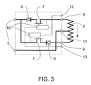
- the commutated electronic power converter object of the invention includes a magnetic core 1, four coils 2 wounds around said core, four input/output ports, each one of which includes a commutating device 3 and a voltage or current sensor 4. Each port also includes its respective terminals 5.
- the converter also includes control means, shown in Figure 5, which on the basis of the signal picked up in the sensors provide the control signals for the commutating devices.
- the commutating device 3 is bipolar and bi-directional and the controls means act on the bipolar and bi-directional commutating device to provide four possible connections of the coil 2, shown in Figure 2, where G represents an e.m.f. and Z an impedance:
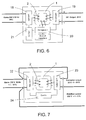
- control means include a micro-controller 14, which determines the commutation priorities of the ports, a non-volatile memory 15, a power-supply circuit 16 and the corresponding input and output circuits.
- Reference number 12 pertains to the power-supply buses
- reference number 13 pertains to the commutation data buses
- reference number 17 to the data input buses of the sensors.
- the converter of the invention includes an alternating current mains input port 22, an alternating current output port, for the load, a storage port 27, for compensating the harmonic and reactive currents, with the aforesaid three ports connected to three independent coils 2 wound around a single core and provided with control means 28 which act on the bipolar and bi-directional commutating devices 3 in such a way that the converter functions as an AC voltage stabiliser, with correction of the power factor at the input and galvanic insulation.
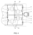
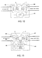
- the converter of the invention includes an alternating mains current input port 29, a direct current output or input port 30, for a battery, with the input/output function of the port changing according to whether or not the input mains is providing energy, an alternating current output port 31, for an uninterrupted supply, and a storage port 32, for compensating the harmonic and reactive currents of the loads, with the aforesaid four ports being connected to four independent coils 2 wound around a single core 1, and being provided with control means 33 which act on the bipolar and bi-directional commutating devices in such a way that the converter functions as an UPS, with input at correction of the power factor.
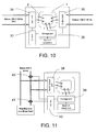
- the converter of the invention includes an alternating current input port 34, an alternating current output port 35, for a non-linear load, a storage port 36, for compensating the harmonic and reactive currents, with the aforesaid three ports connected to three independent coils 2 wound around a single core 1 and provided with control means 37 which act on the bipolar and bi-directional commutating devices 3 in such a way that the converter functions as an insulating transformer / active filter.
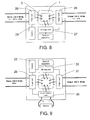
- the converter of the invention includes an alternating current input/output port 38 for supplying the correcting current, a storage port 39, for supplying the harmonic and reactive currents and two current sensors 40 and 41 provided at the input mains, with the two aforesaid ports connected to two independent coils 2 wound on a single core 1 and provided with control means 42 which act on the bipolar and bi-directional commutating devices in such a way that the converter functions as an active correcting filter to compensate reactive and non-linear loads.
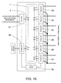
- the converter of the invention includes an alternating current input port 61, for connecting to the single-phase power supply mains, six alternating current output ports 62 to 67, for exa-phasic load, and a storage port 68, for complementing the pulsing power from the input and supplying the direct multiphase power of the outputs, with the eight aforesaid ports connected to eight independent coils 2 wound around a single core 1 and provided with control means 69 which act on the bipolar and bi-directional commutating devices in such a way that the converter functions as mains system transformer, from single-phase to exa-phasic.
Landscapes
- Engineering & Computer Science (AREA)
- Power Engineering (AREA)
- Dc-Dc Converters (AREA)
- Rectifiers (AREA)
Abstract
Description
- "Forward" commutated DC/DC power-supply sources.
- Inverters (DC/AC converters) with pulse-width modulation (PWM) technology.
- Connection with polarity of the coil coinciding with the polarity of an input, with magnetising current travelling in the direction of the input towards the coil.
- Connection with polarity of the coil opposite to the polarity of an input, with magnetising current travelling in the direction of the input towards the coil.
- Connection with polarity of the coil coinciding with the polarity of an output, with demagnetising current travelling in the direction of the coil towards the output.
- Connection with polarity of the coil opposite to the polarity of an output, with demagnetising current travelling in the direction of the coil towards the output.
- Use of a single magnetic component, even for so-far complex conversions.
- Possibility of obtaining "transparency" of the load currents (both of wave shape and of the reactive component) towards the power supply.
- Possibility of modification or correction of the wave shapes (harmonic) and reactive components of the alternating input and/or output currents.
- Possibility of connecting in parallel like outputs of different converters.
- Circulation of energy from one port to others (even of alternating current) in a single conversion.
- Behaviour as a source of current, which provides ease of connection in parallel of two or more devices.
- Galvanic isolation between the various ports.
- Voltage ratios adaptable between the different ports.
- Saving of components, especially electromagnetic components.
- Low weight and volume.
- Connection with polarity of the coil 2 coinciding with the polarity of an input, with magnetising current travelling in the direction of the input towards the coil 2 (diagram A).
- Connection with polarity of the coil 2 opposite to the polarity of an input, with magnetising current travelling in the direction of the input towards the coil 2 (diagram B).
- Connection with polarity of the coil 2 coinciding with the polarity of an output, with demagnetising current travelling in the direction of the coil 2 towards the output (diagram C).
- Connection with polarity of the coil 2 opposite to the polarity of an output, with demagnetising current travelling in the direction of the coil 2 towards the output (diagram D).
Claims (19)
- Commutated electronic power converter, which includes a magnetic core (1), at least two coils (2) wound around said core (1), at least one input port and one output port or a single input/output port, each one of which includes a commutating device (3) and at least one voltage or current sensor (4), while the converter also includes means of control which, on the basis of the signals picked up at the sensor or sensors (3), provide the control signals for the commutating device (4), characterised in that the commutating devices (4) are bipolar and bi-directional, and the control means act on the bipolar and bi-directional commutating devices (3), providing four possible connections of each one of the coils (2):Connection with polarity of the coil (2) coinciding with the polarity of an input, with magnetising current travelling in the direction of the input towards the coil (2).Connection with polarity of the coil (2) opposite to the polarity of an input, with magnetising current travelling in the direction of the input towards the coil (2).Connection with polarity of the coil (2) coinciding with the polarity of an output, with demagnetising current travelling in the direction of the coil (2) towards the output.Connection with polarity of the coil (2) opposite to the polarity of an output, with demagnetising current travelling in the direction of the coil (2) towards the output.
- Converter as claimed in Claim 1, characterised in that the magnetic core (1) includes a magnetic flow sensor which provides the control means with information on the degree of magnetic saturation of the core (1).
- Converter as claimed in Claim 2, characterised in that the magnetic flow sensor includes a Hall-effect device.
- Converter as claimed in Claim 2, characterised in that the magnetic flow sensor includes an additional winding.
- Converter as claimed in Claim 1, characterised in that, in the case of a coil (2) with centre-tap connection (11), the bipolar and bi-directional commutating devices (3) include a pair of diodes (6) each connected in series with a transistor (7) between one of the ends (8,9) of the coil (2) and one of the poles (5) of the input/output port, with the diodes (6) and the transistors (7) being mounted in the opposite direction.
- Converter as claimed in Claim 1, characterised in that, in the case of a simple coil (2), the bipolar and bi-directional commutating devices (3) include four diodes (6) in bridge configuration and four transistors (7) connected in series to each of the diodes (6).
- Converter as claimed in Claim 1, characterised in that it includes, in addition to the sensors included in the ports, at least another auxiliary sensor (40, 41).
- Converter as claimed in Claim 1, characterised in that the means of control include a micro-controller (14), which determines the commutating priorities of the ports, a non-volatile memory (15), a power-supply circuit (16) and the corresponding input and output circuits.
- Converter as claimed in any of Claims 1 to 4, characterised in that includes an alternating current input port (18), a direct current output port (19) for the load and a storage port (20), for compensating the harmonic and reactive currents, with the aforesaid three ports connected to three independent coils (2) wound around a single core (1), and in that the control means (21) act on the bipolar and bi-directional commutating devices (3) in such a way that the converter functions as an AC/DC power supply with correction of the power factor at the input.
- Converter as claimed in any of Claims 1 to 4, characterised in that it includes an alternating current mains input port (22), an alternating current output port (23), for supplying the correcting voltage and current, the aforesaid two ports being connected to two independent coils (2) wound around a single core (1), and in that the control means (24) act on the bipolar and bi-directional commutating devices (3) in such a way that the converter functions as an AC voltage stabiliser.
- Converter as claimed in any of Claims 1 to 4, characterised in that it includes an alternating current mains input port (22), an alternating current output port (26), for the load, a storage port (27), for compensating the harmonic and reactive currents, with the aforesaid three ports connected to three independent coils (2) wound around a single core (1), and in that the control means (28) act on the bipolar and bi-directional commutating devices (3) in such a way that the converter functions as an AC voltage stabiliser, with correction of the power factor at the input and galvanic insulation.
- Converter as claimed in any of Claims 1 to 4, characterised in that it includes an alternating mains current input port (29), a direct current output or input port (30), for a battery, with the input/output function of the port changing according to whether or not the input mains is providing energy, an alternating current output port (31), for an uninterrupted supply, and a storage port (32), for compensating the harmonic and reactive currents of the loads, with the aforesaid four ports being connected to four independent coils (2) wound around a single core (1), and in that the control means (33) act on the bipolar and bi-directional commutating devices in such a way that the converter functions as an UPS, with input at correction of the power factor.
- Converter as claimed in any of Claims 1 to 4, characterised in that it includes an alternating current input port (34), an alternating current output port (35), for a non-linear load, a storage port (36), for compensating the harmonic and reactive currents, with the aforesaid three ports connected to three independent coils (2) wound around a single core (1), and in that the control means (37) act on the bipolar and bi-directional commutating devices (3) in such a way that the converter functions as an insulating transformer / active filter.
- Converter as claimed in any of Claims 1 to 4, characterised in that it includes an alternating current input/output port (38) for supplying the correcting current, a storage port (39), for supplying the harmonic and reactive currents and two current sensors (40, 41) provided at the input mains, with the two aforesaid ports connected to two independent coils (2) wound on a single core (1), and in that the control means (42) act on the bipolar and bi-directional commutating devices (3) in such a way that the converter functions as an active correcting filter to compensate reactive and non-linear loads.
- Converter as claimed in any of Claims 1 to 4, characterised in that it includes a direct current input port (43), an alternating current output port (44), for the load, with the aforesaid two ports connected to two independent coils (2) wound on a single core (1), and in that the control means (45) act on the bipolar and bi-directional commutating devices (3) in such a way that the converter functions as an inverter.
- Converter as claimed in any of Claims 1 to 4, characterised in that it includes a direct current battery input port (46), an alternating current output port (47), for the load, and a storage port (48), for compensating the harmonic and reactive currents, with the three aforesaid ports connected to three independent coils (2) wound around a single core (1), and in that the control means (49) act on the bipolar and bi-directional commutating devices (3) in such a way that the converter functions as an inverter with active filter of harmonic and non-linear load currents.
- Converter as claimed in any of Claims 1 to 4, characterised in that it includes an alternating current input port (50), for connecting to the single-phase power supply mains, three alternating current output ports (51,52,53) for a three-phase load, and a storage port (54), for complementing the pulsing power from the input and supplying the direct multiphase power of the outputs during the passing through zero of the input voltage, with the five aforesaid ports connected to five independent coils (2) wound around a single core (1), and in that the control means (55) act on the bipolar and bi-directional commutating devices (3) in such a way that the converter functions as mains system transformer, from single-phase to three-phase.
- Converter as claimed in any of Claims 1 to 4, characterised in that it includes an alternating current input port (56), for connecting to the single-phase power supply mains, two alternating current output ports (57,58) for a bi-phase load, a storage port (59), for complementing the pulsing power from the input and supplying the direct multiphase power of the outputs, with the four aforesaid ports connected to four independent coils (2) wound around a single core (1), and in that the control means (60) act on the bipolar and bi-directional commutating devices (3) in such a way that the converter functions as a mains system transformer, from single-phase to bi-phase.
- Converter as claimed in any of Claims 1 to 4, characterised in that it includes an alternating current input port (61), for connecting to the single-phase power supply mains, six alternating current output ports (62, 63, 64, 65, 66, 67), for exa-phasic load, and a storage port (68), for complementing the pulsing power from the input and supplying the direct multiphase power of the outputs, with the eight aforesaid ports connected to eight independent coils (2) wound around a single core (1), and in that the control means (69) act on the bipolar and bi-directional commutating devices (3) in such a way that the converter functions as mains system transformer, from single-phase to exa-phasic.
Applications Claiming Priority (2)
| Application Number | Priority Date | Filing Date | Title |
|---|---|---|---|
| ES200102274A ES2185515B1 (en) | 2001-10-15 | 2001-10-15 | POWER SWITCHED ELECTRONIC CONVERTER. |
| ES200102274 | 2001-10-15 |
Publications (2)
| Publication Number | Publication Date |
|---|---|
| EP1303031A2 true EP1303031A2 (en) | 2003-04-16 |
| EP1303031A3 EP1303031A3 (en) | 2005-04-13 |
Family
ID=8499172
Family Applications (1)
| Application Number | Title | Priority Date | Filing Date |
|---|---|---|---|
| EP02380209A Withdrawn EP1303031A3 (en) | 2001-10-15 | 2002-10-11 | Commutated electronic power converter |
Country Status (2)
| Country | Link |
|---|---|
| EP (1) | EP1303031A3 (en) |
| ES (1) | ES2185515B1 (en) |
Cited By (4)
| Publication number | Priority date | Publication date | Assignee | Title |
|---|---|---|---|---|
| EP1687892A4 (en) * | 2003-11-25 | 2012-01-18 | Electric Power Res Inst | UNIVERSAL DIFFERENTIAL TRANSFORMER WITH MULTIPLE FUNCTIONS |
| WO2013075735A1 (en) * | 2011-11-22 | 2013-05-30 | Abb Technology Ag | High voltage dc/dc converter with transformer driven by modular multilevel converters (mmc) |
| EP3267545A1 (en) * | 2016-07-04 | 2018-01-10 | eQnizer AG | Alternate current (ac) voltage stabilizer |
| CN113219375A (en) * | 2021-03-29 | 2021-08-06 | 广东电网有限责任公司 | Method and system for testing operation reliability of power electronic transformer |
Family Cites Families (15)
| Publication number | Priority date | Publication date | Assignee | Title |
|---|---|---|---|---|
| GB1542664A (en) * | 1975-12-12 | 1979-03-21 | Ibm | Fly-back type converter |
| DE2728377A1 (en) * | 1977-06-23 | 1979-01-11 | Siemens Ag | CIRCUIT ARRANGEMENT FOR THE CONVERSION OF ELECTRICAL ENERGY |
| EP0403595A1 (en) * | 1988-07-20 | 1990-12-27 | Power Reflex Pty. Ltd. | Switched electrical power conversion and balancing |
| US5029064A (en) * | 1989-09-29 | 1991-07-02 | Ball Newton E | Phase-controlled reversible power conversion with equal duty cycle substantially constant amplitude square wave excitation of the power transformer |
| US5220492A (en) * | 1989-12-26 | 1993-06-15 | Systel Development And Industries Ltd. | Inverter and power supply systems including same |
| US5150270A (en) * | 1991-03-01 | 1992-09-22 | Dowty Rfl Industries, Inc. | Transformer circuit and method with saturation prevention |
| FR2674386B1 (en) * | 1991-03-18 | 1993-07-23 | Sgs Thomson Microelectronics | SYSTEM FOR CONTROLLING AN INVERTER BY PULSE WIDTH MODULATION. |
| JP2957344B2 (en) * | 1992-03-06 | 1999-10-04 | 日野自動車工業株式会社 | Bidirectional DC / DC converter |
| DE4435351C1 (en) * | 1994-09-21 | 1996-03-21 | Aeg Schienenfahrzeuge | Method for regulating a four-quadrant controller acting as a power converter |
| JPH08228484A (en) * | 1995-02-21 | 1996-09-03 | Nippon Electric Ind Co Ltd | Phase control smr converter |
| DE19524963A1 (en) * | 1995-07-08 | 1997-01-09 | Bosch Gmbh Robert | Switching power supply with B control |
| DE19542163A1 (en) * | 1995-11-11 | 1997-01-16 | Abb Daimler Benz Transp | Control of rectifier output voltage e.g. for electrical supply of electric vehicles - has gate voltage taken from regulator which uses discrepancy in rectifier output voltage and reactive input current as parameters |
| ES2122902B1 (en) * | 1996-06-06 | 1999-07-16 | Univ Valencia | FOUR QUADRANT REGULATOR FOR DC / DC OR AC / DC POWER CONVERTER. |
| AT409437B (en) * | 1997-09-15 | 2002-08-26 | Croce Wolfgang | METHOD FOR OPTIMIZING THE PERFORMANCE OF SWITCHING POWER SUPPLIES |
| WO2001043267A1 (en) * | 1999-12-07 | 2001-06-14 | Advanced Energy Industries, Inc. | Power supply with flux-controlled transformer |
-
2001
- 2001-10-15 ES ES200102274A patent/ES2185515B1/en not_active Expired - Fee Related
-
2002
- 2002-10-11 EP EP02380209A patent/EP1303031A3/en not_active Withdrawn
Cited By (5)
| Publication number | Priority date | Publication date | Assignee | Title |
|---|---|---|---|---|
| EP1687892A4 (en) * | 2003-11-25 | 2012-01-18 | Electric Power Res Inst | UNIVERSAL DIFFERENTIAL TRANSFORMER WITH MULTIPLE FUNCTIONS |
| WO2013075735A1 (en) * | 2011-11-22 | 2013-05-30 | Abb Technology Ag | High voltage dc/dc converter with transformer driven by modular multilevel converters (mmc) |
| EP3267545A1 (en) * | 2016-07-04 | 2018-01-10 | eQnizer AG | Alternate current (ac) voltage stabilizer |
| WO2018007881A1 (en) * | 2016-07-04 | 2018-01-11 | Eqnizer Ag | Alternate current (ac) voltage stabilizer |
| CN113219375A (en) * | 2021-03-29 | 2021-08-06 | 广东电网有限责任公司 | Method and system for testing operation reliability of power electronic transformer |
Also Published As
| Publication number | Publication date |
|---|---|
| EP1303031A3 (en) | 2005-04-13 |
| ES2185515A1 (en) | 2003-04-16 |
| ES2185515B1 (en) | 2004-02-16 |
Similar Documents
| Publication | Publication Date | Title |
|---|---|---|
| JP4910078B1 (en) | DC / DC converter and AC / DC converter | |
| CN110139775B (en) | Method for controlling a charging device on board an electric or hybrid vehicle | |
| US6021052A (en) | DC/AC power converter | |
| US6664762B2 (en) | High voltage battery charger | |
| EP3337024B1 (en) | Bidirectional resonant conversion circuit and converter | |
| US5852558A (en) | Method and apparatus for reducing common mode voltage in multi-phase power converters | |
| US5668707A (en) | Multi-phase power converter with harmonic neutralization | |
| US5943229A (en) | Solid state transformer | |
| US8737097B1 (en) | Electronically isolated method for an auto transformer 12-pulse rectification scheme suitable for use with variable frequency drives | |
| US10840814B2 (en) | Power conversion system | |
| US20020141216A1 (en) | Multi-output power conversion circuit | |
| EA008239B1 (en) | Charge transfer apparatus and method therefor | |
| EP3635852A1 (en) | Power converter | |
| US11065968B2 (en) | Integrated multi-source IPT system | |
| GB2294165A (en) | Power supply for providing a dc supply from a multiphase ac source | |
| US5587892A (en) | Multi-phase power converter with harmonic neutralization | |
| EP4723453A1 (en) | Three-phase-power-based power supply circuit and method for same to realize pfc/voltage boosting/voltage reduction | |
| US5625543A (en) | Power converter with harmonic neutralization | |
| EP1303031A2 (en) | Commutated electronic power converter | |
| US11791739B2 (en) | AC-AC converter | |
| WO2019213673A1 (en) | Buck matrix-type rectifier with boost switch, and operation thereof during one-phase loss | |
| CN101199108B (en) | Method and converter for converting a DC voltage to a three-phase AC output | |
| SU736298A1 (en) | Ac-to-dc voltage converter | |
| RU2187872C1 (en) | Hybrid passive power corrector and its control process | |
| CN119787844B (en) | Three-phase single-stage isolated rectifier and control method |
Legal Events
| Date | Code | Title | Description |
|---|---|---|---|
| PUAI | Public reference made under article 153(3) epc to a published international application that has entered the european phase |
Free format text: ORIGINAL CODE: 0009012 |
|
| AK | Designated contracting states |
Designated state(s): AT BE BG CH CY CZ DE DK EE ES FI FR GB GR IE IT LI LU MC NL PT SE SK TR |
|
| AX | Request for extension of the european patent |
Extension state: AL LT LV MK RO SI |
|
| RIC1 | Information provided on ipc code assigned before grant |
Ipc: 7H 02J 9/06 B Ipc: 7H 02J 3/18 B Ipc: 7H 02M 1/00 B Ipc: 7H 02M 3/337 B Ipc: 7H 02M 5/14 B Ipc: 7H 02M 5/10 A |
|
| PUAL | Search report despatched |
Free format text: ORIGINAL CODE: 0009013 |
|
| AK | Designated contracting states |
Kind code of ref document: A3 Designated state(s): AT BE BG CH CY CZ DE DK EE ES FI FR GB GR IE IT LI LU MC NL PT SE SK TR |
|
| AX | Request for extension of the european patent |
Extension state: AL LT LV MK RO SI |
|
| 17P | Request for examination filed |
Effective date: 20050930 |
|
| AKX | Designation fees paid |
Designated state(s): AT BE BG CH CY CZ DE DK EE ES FI FR GB GR IE IT LI LU MC NL PT SE SK TR |
|
| AXX | Extension fees paid |
Extension state: SI Payment date: 20050930 Extension state: RO Payment date: 20050930 Extension state: MK Payment date: 20050930 Extension state: LV Payment date: 20050930 Extension state: LT Payment date: 20050930 Extension state: AL Payment date: 20050930 |
|
| 17Q | First examination report despatched |
Effective date: 20100413 |
|
| STAA | Information on the status of an ep patent application or granted ep patent |
Free format text: STATUS: THE APPLICATION IS DEEMED TO BE WITHDRAWN |
|
| 18D | Application deemed to be withdrawn |
Effective date: 20101026 |