EP1302840A2 - Power supply control in network - Google Patents
Power supply control in network Download PDFInfo
- Publication number
- EP1302840A2 EP1302840A2 EP02251714A EP02251714A EP1302840A2 EP 1302840 A2 EP1302840 A2 EP 1302840A2 EP 02251714 A EP02251714 A EP 02251714A EP 02251714 A EP02251714 A EP 02251714A EP 1302840 A2 EP1302840 A2 EP 1302840A2
- Authority
- EP
- European Patent Office
- Prior art keywords
- power
- information processing
- supply control
- date
- time
- Prior art date
- Legal status (The legal status is an assumption and is not a legal conclusion. Google has not performed a legal analysis and makes no representation as to the accuracy of the status listed.)
- Ceased
Links
Images


Classifications
-
- G—PHYSICS
- G06—COMPUTING; CALCULATING OR COUNTING
- G06F—ELECTRIC DIGITAL DATA PROCESSING
- G06F15/00—Digital computers in general; Data processing equipment in general
- G06F15/16—Combinations of two or more digital computers each having at least an arithmetic unit, a program unit and a register, e.g. for a simultaneous processing of several programs
-
- G—PHYSICS
- G06—COMPUTING; CALCULATING OR COUNTING
- G06F—ELECTRIC DIGITAL DATA PROCESSING
- G06F1/00—Details not covered by groups G06F3/00 - G06F13/00 and G06F21/00
- G06F1/26—Power supply means, e.g. regulation thereof
Definitions
- the present invention relates to a centralized management/control method for the power ON/OFF schedule of a plurality of computers in a system in which the plurality of computers are connected via a network.
- the power of a computer (such as a server in a network) is automatically turned ON/OFF according to a predetermined schedule in an automatic power supply control method.
- This method is used to make the computer carry out a series (schedule) of operating jobs from power-up to the activation and completion of an application, and saves the labor and resources required to operate the computer (automatic operation).
- FIG. 1 shows a conventional automatic power supply control method.
- a power supply control device 102 is connected to a single computer 101.
- the power supply control device 102 can be an exclusive device (standalone device), and can be configured to have the function of controlling the power supply by, for example, a UPS (uninterruptible power supply, also referred to as a standby power supply device), etc.
- UPS uninterruptible power supply
- the computer 101 is provided with power supply scheduling software 103.
- a settings input screen (not shown in the attached drawings) of a power supply schedule is displayed.
- the user defines (inputs the settings of) a power supply schedule (power-up date and time, shutdown/power-down date and time, etc.) or a 'wait event' for extending the shutdown.
- the 'wait event' refers to a state to be reached before the computer 101 can safely shut down. For example, an operation job is terminated, a database is completed, etc. Therefore, if the 'wait event' has not occurred by the power-down date and time, then it is necessary to extend the power-down date and time without performing the shutdown process.
- An example of the above mentioned 'wait event' can be an 'end of operation job' and an 'end of database' because the computer 101 is not necessarily operated by a person, but automatically continues executing jobs according to a predetermined job schedule during its operating time. However, it is not limited to these applications.
- the above mentioned power supply schedule can be set for several weeks or months, and for a plurality of dates and times.
- the power supply schedule software 103 enters a wait state until the earliest date and time for shutdown/power-down.
- the power supply control device 102 is instructed to indicate the next power-up date and time and perform a shut down process in several minutes according to the defined power supply schedule, unless it is necessary to extend the power-down date and time until after it is confirmed that the 'wait event' has occurred.
- the OS operating system
- the power-down process may be delayed by up to several minutes, to prevent the power-down from being performed before the completion of the shutdown.
- the OS of the computer 101 is shut down, and then the power-down process is performed by the power supply control device 102.
- the power supply control device 102 obviously stores the indicated next power-up date and time in its internal memory, or the like.
- the power supply control device 102 performs the power-up process such as energizing, etc. Through the power-up, the computer 101 can be activated.
- a system involving a plurality of computers refers to, for example, a client/server system, and specifically a system in which the plurality of computers perform a formatted job in cooperation with one another according to the schedule of a predetermined job.
- this system it is desired that the processes of power-up, system activation, activation of a job application, stopping the job application, shutdown, and power-down can be automatically operated by calendar control.
- multiserver systems for allowing large amounts of access at several sites on the Internet.
- an automatic power supply schedule management system is needed to perform the power-down process when a power supply ON/OFF scheduling process is performed on each server each week (for example, to stop the operation on Sundays, etc.), during the periodic maintenance, at the beginning and the end of a year, etc.
- the management system for an automatic power supply schedule of a single computer is applied as is. That is, each computer is provided with its own power supply control device 102 and the power supply schedule software 103 for individual management of the power supply schedule.
- a plurality of computers 111, 121, 131, and 141 are provided with power supply control devices 112, 122, 132, and 142. They are connected to a network (not shown) and can communicate with one another.
- One of the plurality of computers 111 to 141 is chosen as a representative computer, and the representative computer collectively manages/controls the power supply ON/OFF scheduling of all the computers including itself.
- the computer 111 is the representative computer.
- the representative computer 111 comprises a power supply scheduling unit 111a which collectively manages/controls the power ON/OFF scheduling (to be defined by a manager, etc.) for all the computers. That is, the power supply scheduling unit 111a requests the other computers 121 through 141 to perform the power-down process each time a defined power-down date and time is received according to a predetermined schedule. Correspondingly, each of the computers 121, 131, and 141 instructs its power supply control device 122, 132, or 142 to perform the power-down process and power itself down. Then, the power supply scheduling unit 111a notifies its own power supply control device 112 of the next power-up date and time, instructs it to enter (store) that date and time, performs the power-down process, and powers itself down.
- the power supply control device 112 powers up the computer 111.
- the power supply scheduling unit 111a instructs the power supply control devices 122, 132, and 142 of the other computers to perform the power-up process.
- each of the computers 121, 131, and 141 is powered up.
- the present invention aims at providing a supply control method for a plurality of information processing devices, for use with a configuration in which the automatic power supply ON/OFF schedules of a plurality of computers are collectively managed/controlled by a representative computer, capable of activating computers even if the representative computer becomes faulty, and performing startup/power-down process in a specific order despite possible errors, etc. in the clock.
- the first method is a power supply control method for use in a system in which a power supply control device is provided for each of the information processing devices connected to a network.
- An arbitrary one of the plurality of information processing devices instructs each power supply control device of the other information processing devices to perform a power-up process each time it is activated according to a predetermined power-up/down schedule of itself and the other information processing devices, notifies the other information processing devices of the next power-up date and time together with a power-down instruction each time a power-down date and time comes, and allows each power supply control device to enter (store) the next power-up date and time.
- the power supply control device of each other information processing device receives the power-up instruction or the entered power-up date and time comes, it performs the power-up process.
- the second method is likewise for use in a system in which a power supply control device is provided for each of the information processing devices connected to a network.
- An arbitrary one of the plurality of information processing devices instructs each power supply control device of the other information processing devices to perform a power-up process each time it is activated according to a predetermined power-up/down schedule of itself and the other information processing devices, notifies each power supply control device of the other information processing devices of the next power-up date and time and has it enter the date and time each time a power-down date and time comes, and issues a power-down instruction to each information processing device.
- the power supply control device of each other information processing device receives the power-up instruction or the entered power-up date and time comes, it performs the power-up process.
- the power supply control device of each other information processing device enters the next power-up date and time in the power-down process so that the other information processing devices can be activated even when a power-up instruction is not issued because an abnormal condition, for example, in which any information processing device cannot be activated for any reason, occurs when the next power-up date and time comes.
- next power-up date and time given to each power supply control device of the other information processing devices can be the date and time obtained by any information processing device or each information processing device adding any margin to the power-up date and time in the power-up/down schedule set in advance.
- each power supply control device of the other information processing devices is a little fast (or slow)
- the power-up process can be performed when there is no power-up instruction even after, for example, about ten minutes have passed from the original power-up date and time.
- the representative information processing device is normally activated, the problem that the system is activated earlier than a scheduled date and time and the defined activation order cannot be guaranteed, can be avoided.
- FIG. 3 is a general view of a system for performing an automatic power supply schedule of a plurality of computers embodying the present invention.
- FIG. 3 shows a system in which computers 11, 21, 31, and 41 are connected to a network (LAN, etc.) not shown in the attached drawings.
- Each of power supply control devices 12, 22, 32, and 42 is also connected to the network.
- the communications between computers, or between the computer 11 and each of the supply control devices 22, 32, and 42, through the network are performed through, for example, an Ethernet protocol.
- any one of the plurality of computers 11 through 41 is chosen to be a representative computer, and the representative computer is allowed to collectively manage/control the automatic power ON/OFF schedule of its own and other computers.
- the computer 11 is the representative computer.
- the computer 11 comprises a power supply schedule management/control unit 11a, and collectively manages/controls its own power supply schedule (date and time on which the power is turned ON/OFF) as well as that of the other computers 21, 31, and 41.
- the power supply schedule management/control unit 11a requests the other computers 21, 31, and 41 to power down each time the power-down date and time comes according to a predetermined power supply schedule. At this time, the next power-up date and time is notified.
- power supply management units 21a, 31a, and 41a of each of the computers 21, 31, and 41 have their own supply control devices 22, 32, and 42 enter the power-up dates and times, and instruct them to perform the power-down process.
- the supply control devices 22, 32, and 42 power down the computers 21, 31, and 41 respectively.
- the power supply schedule management/control unit 11a of the computer 11 has the supply control device 12 enter the power-up date and time, and instructs it to perform the power-down process.
- the supply control device 12 powers down the computer 11.
- the power-up date and time entered by the supply control device 12 is set such that the supply control device 12 can be powered up a little earlier than the other supply control devices 22, 32, and 42.
- the power-up date and time entered in the supply control device 12 comes first, and the supply control device 12 powers up the computer 11.
- the power supply schedule management/control unit 11a requests each of the supply control devices 22, 32, and 42 to perform the power-up process.
- the supply control devices 22, 32, and 42 power up the computers 21, 31, and 41 respectively.
- the supply control devices 22, 32, and 42 power up the computers 21, 31, and 41 respectively when the entered power-up date and time is reached during the power-down state.
- the risk that the other computers 21, 31, and 41 cannot be powered up can be avoided even if the representative computer 11 cannot be activated.
- the representative computer 11 cannot be activated.
- another computer can replace that computer, thereby preventing trouble.
- the representative computer 11 starts the power-down process as soon as the power-down date and time comes, but the power-down process can be delayed until an 'event' predetermined for all computers including the computer 11 has occurred even after the power-down date and time has arrived (such that the shutdown can be extended) Furthermore, each computer can be set to be powered down or up at predetermined time intervals. The details are described later.
- FIG. 4 shows the definition of the automatic power supply schedule.
- a schedule definition 50 shown in FIG. 4 comprises a startup/power-down time 51, a computer name 52 to be controlled in synchronization, and an event name 53 awaiting the shutdown.
- startup/power-down time 51 is defined every day in this example (startup at 6:00 and power-down at 20:00), the settings are not limited to these values. For example, it can be newly set every week as on a schedule definition setting screen 60 shown in FIG. 5, and can be configured, and also can be newly set every day.
- an operation time setting area 61, an 'operation' button 62, an 'OFF' button 63, a 'reboot' button 64, etc. can be displayed.
- a desired operation time period he or she specifies a desired time period in the operation time setting area 61 after specifying the 'operation' button 62.
- a shutdown time period and a reboot time can be specified by operating the 'OFF' button 63 and the 'reboot' button 64 respectively.
- the system is activated at 6:00 and powered down at 20:00 on Monday, Tuesday, and Thursday every week. For example, on Saturday, the system is set to be activated at 6:00, suspended at 12:00, then activated again at 16:00, and powered down at 20:00.
- Each computer name 52 to be controlled in synchronization is formed by a computer name 52a (which can be an identifier such as an ID, etc.), a startup interval 52b, a power-down interval 52c, and an IP address 52d of the supply control device in this example.
- the computer names 52a are linked with one another (including the computer 11).
- the name, the identifier, etc. of a computer for performing a formatted job process, etc. are defined.
- a plurality of computers linked with one another are also linked in the power ON/OFF control.
- the computers 21, 31, and 41 are entered as the computers which are linked in control, and are collectively managed/controlled in the power ON/OFF process by the computer 11 (the computers can be hereinafter referred to as a 'target computer').
- the startup interval 52b is defined when the computers 21, 31, and 41 are to be activated in order at arbitrary time intervals.
- the power-down interval 52c is similarly defined. Therefore, they are not necessarily defined.
- the computers are activated in order from top to bottom.
- the computers 21, 31, and 41 are activated in this order.
- they are powered down in order from the computers 41, 31, and 21.
- the computer 31 (also the computer 21 in this example) is set to be powered down one minute after the computer 41 is powered down. Intervals are not necessarily set among the computers for the startup/power-down process. If they are not set, '0 minute' is set as shown in FIG. 4A.
- FIG. 4A shows only an example.
- the IP address assigned to each supply control device is defined to the IP address 52d of the supply control device. Normally, although the IP address of each of the computers 11 through 41 is entered (since it is a matter of fact, it is not specifically shown or described), the IP address of the supply control device itself is not entered. Therefore, it is defined below.
- the representative computer 11 can issue a power-up instruction, a power-down instruction, etc. directly to each supply control device using the IP address 52d of the supply control device.
- the set contents are stored in a supply control target computer definition file 54 as shown in FIG. 4B.
- 'COMPUTERB' is an example of an actual computer name (or identifier) of the computer 21.
- a definition file for correspondence between the IP address of each computer and the computer name is also stored.
- FIG. 6 shows an example of a setting screen for allowing a user to define the computer names 52 to be controlled in synchronization.
- a setting screen 70 the user first specifies, for example, an 'add' button 72, a 'change' button 73, etc. and then sets/inputs the name of the host to be power-controlled, the startup interval, the power-down interval, the IP address 52d of the UPS (supply control device), etc. in a setting input area 71.
- the unit of the values of the startup interval and the power-down interval is 'second'.
- a condition name (in the example shown in FIG. 4, the end of the database, the end of the operation job, and other information such as waiting for the output of the printer, etc.) indicating that it is time to enter a power-down state is entered for each computer in an event name 53 which is waiting for shutdown.
- a 'waiting event name' of the user's computer (representative computer) is also entered as in the conventional technology.
- a 'waiting event name' of not only the representative computer but also other computers to be power ON/OFF controlled in synchronization
- the shutdown process is not performed until a 'waiting event' occurs in all computers (until it is time to enter a shutdown state) although the power-down date and time has come. That is, a 'wait event' refers to also a power-down permission condition.
- FIG. 7 is a flowchart for explanation of an example of a power-down process in the system shown in FIG. 3.
- FIG. 7 shows only one computer 21 (and its supply control device 22) as another computer which is managed/instructed by the representative computer 11 for its power supply schedule. However, similar processes are performed on other computers 31 and 41, and the same applies to Figs. 8 to Fig. 11.
- the computer 11 upon receipt of the notification, the computer 11 temporarily records that the event has occurred in the computer 21.
- the computer 11 normally performs its own job process, etc. until a predetermined power-down time comes (NO in step S11), and temporarily stores it each time another computer notifies the computer 11 of the occurrence of an event (or when an event occurs in the computer 11). At the power-down time, the computer 11 determines whether or not events have occurred (been completed) in all computers. If not (NO in step S11), the computer 11 waits until the events have been completed (extends the shutdown).
- step S11 If the power-down time has come, and the events have been completed in all computers (YES in step S11), then the power-down process described below is performed.
- the power-down process can be started at the power-down time without considering the completion of an event. If a new process occurs after receipt of the notification of the occurrence of an event in another computer, then a notification of the deletion of the occurrence of the event is issued, and a notification of the occurrence of the event is issued again upon completion of the new process. Otherwise, if the power-down time has come, not when another computer issues an event occurrence notification by itself, then the computer 11 can issue an inquiry to another computer.
- the computer 11 refers to a startup/power-down time 51 and a computer name 52 to be controlled in synchronization in the above mentioned schedule definition 50, and obtains the next power-up time of each computer for managing a power supply schedule (step S12).
- the power-up time is 6:00 for the computers 11 and 21, 6:03 for the computer 31, and 6:05 for the computer 41.
- steps S14 to S16 are performed on all computers to be managed for power supply schedules (step S13) .
- an appropriate margin (predetermined by an operator, etc., or optionally determined by a computer, and assumed to be 10 minutes in the present embodiment) is allowed for the next power-up time obtained in step S12 for a target computer (step S14). That is, the next power-up time is given in step S15 for use in case the computer 11 cannot be activated.
- the supply control device 32 of the computer 31 enters '6:03' as the next power-up time, the supply control device 32 can activate the computer 31 before the computer 11 instructs it to perform the power-up process for any reason (for example, the clock is a little fast) although the computer 11 is normally activated. To avoid such an error (the power-up process cannot be performed in the defined order), an appropriate margin is allowed.
- steps S14 and S33 need not be simultaneously performed. That is, the process of allowing a margin for the next power-up time can be performed by the representative computer 11 or each of the computers 21, 31, and 41 whichever can be predetermined before a program is generated.
- steps S14 and S33 are not necessarily required. For example, if a value of a predetermined power-up/down interval includes an allowed margin, they are not required (however, in this case, a user, etc. has to perform a setting operation with the margin taken into account).
- the computer 11 requests a target computer to perform a power-down process via the network, and notifies the target computer of the next power-up time (if the computer 11 adds a margin, then the value contains the margin)(for example, in the parameter form).
- steps S14 through S16 are performed if another target computer exists.
- steps S14 through S16 are explained below by referring to the example shown in FIG. 4A.
- the power-down process is performed by following the power-up process steps in reverse. Therefore, the computer 41 is processed first. Since the power-up time of the computer 41 is 6:05, if a margin(10 minutes) is added in step S14, the power-up time notified for the computer 41 in step S15 is 6:15, which is given to the computer 41 that is requested to perform the power-down process. Then, after one minute, the process is started on the computer 31.
- step S13 When the processes on all target computers are completed (NO in step S13), the computer 11 notifies its supply control device 12 of the power-up time, and instructs it to perform the power-down process (step S17), thereby performing the shutdown process (step S18) .
- the supply control device 12 stores the received next power-up time in an internal memory (not shown) (step S19). Then, after a period (several minutes) predetermined such that the power cannot be turned off before the shutdown is completed (step S20), the computer 11 is turned off (step S21).
- each of the computers 21, 31, and 41 upon receipt of the next power-up time notification and the power-down instruction in step S15 (step S32), each of the computers 21, 31, and 41 performs the process of allowing a margin at (adding a few minutes to) a received next power-up time. If this is done, there is no need for the representative computer to perform the process in step S14 (step S33).
- step S34 the next power-up time assigned a margin in step S14 or S33 is given to the power supply controller (the supply control device 22 in the example shown in FIG. 7) of the computer, and the power-down instruction is issued (step S34). Then, the shutdown process is performed (step S35).
- the supply control device 22 stores the received next power-up time in the memory, etc. (step S36). Then, after a predetermined period (several minutes) to ensure that the power is not lost before the shutdown is completed (step S37), the power-down process is performed on the computer 21 (step S38). Similar processes are performed by the other supply control devices 32 and 42.
- FIG. 8 is a flowchart for explanation of the power-up process in the normal operation.
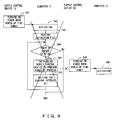
- FIG. 9 is a flowchart for explanation of the power-up process in an abnormal condition (fault in representative computer 11).
- the supply control device 12 of the representative computer 11 starts turning on the computer 11 at the entered power-up date and time (step S41).
- step S42 the power supply schedule management/control unit 11a reads the supply control target computer definition file 54, for example, shown in FIG. 4B (step S43), and sequentially issues a power-up instruction to the supply control devices for each of the supply control target computers defined in the definition file 54 (step S45). If the startup interval is set, the process on the next supply control target computer is started after the startup interval (step S46). If there is no more power-up target (NO in step S44), then the process terminates.
- the destination of the instruction in step S45 can be obtained by referring to the IP address of the supply control device of the supply control target computer definition file 54.
- each of the supply control target computers of the supply control devices 22, 32, and 42 Upon receipt of the power-up instruction by step S45, each of the supply control target computers of the supply control devices 22, 32, and 42 starts turning on its own computer (step S47). Thus, each of the computers 21, 31, and 41 is activated (possibly at the startup interval) (step S48) .
- the supply control device 12 of the representative computer 11 first starts turning on the computer 11 (step S41).
- step S48 Assume that the computer 11 cannot be activated for some reason although the computer 21 etc. can be normally activated. In this case, it is obvious that the processes in steps S43 through S46 are not performed (as indicated by the big x mark shown in FIG. 9). Therefore, time passes without any power-up instruction to each of the supply control devices 22, 32, and 42. Then, if each of the supply control devices 22, 32, and 42 determines that the power-up date and time entered in step S36 has come, then its own computer is turned on (step S49). Thus, each of the computers 21, 31, and 41 can be activated even though the computer 11 is in an abnormal condition and the activation is realized a little after the original power-up time (delayed by the margin added in step S14 or S33) (step S48).
- FIG. 10 is a general view of the above mentioned process flow of the case in which the definition shown in FIG. 4A is set.
- FIG. 10 the definition of the schedule in the computer 11 is shown in FIG. 4A as described above.
- the supply control device 12 powers up the computer 11 at the power-up date and time (6:00) notified and entered during power-down.
- the computer 11 activates the OS, and requests the supply control device 22 to perform the power-up process based on the definition shown in FIG. 4A.
- the supply control device 22 powers up the computer 21.
- the computers 11 through 41 After the activation, the computers 11 through 41 perform their respective processes. When the 'wait event for shutdown' is completed, they notify the computer 11 of the completion. In the example shown in FIG. 10, the computer 21 notifies the computer 11 of the end of (completion of processing of) the database.
- the computer 11 starts the power-down process when the next power-down date and time comes and all computers notify the computer 11 that the 'wait event for shutdown' has been completed.
- the process of assigning a margin is performed by each of the computers 21, 31, and 41 (that is, the process in step S14 shown in FIG. 7 is not performed, but the process in step S33 is performed).
- the computer 11 first requests the computer 41 to perform the power-down process, and notifies the computer 41 of the next power-up date and time (6:05).
- the computer 41 notifies the supply control device 42 of the next power-up date and time (6:15) obtained by adding a predetermined margin (10 minutes) to the power-up date and time (6:05), and simultaneously instructs it to perform the power-down process.
- the computer 11 requests the computers 31 and 21 to perform the power-down process.
- the next power-up date and time given then is 6:03 for the computer 31, and 6:00 for the computer 21.
- the computer 31 notifies the supply control device 32 of the next power-up date and time (6:13) obtained by adding a predetermined margin (10 minutes) to the power-up date and time (6:03), and simultaneously instructs it to perform the power-down process.
- the computer 21 notifies the supply control device 22 of the next power-up date and time (6:10) obtained by adding a predetermined margin (10 minutes) to the power-up date and time (6:00), and simultaneously instructs it to perform the power-down process.
- the supply control device 22 activates the computer 21 at a request from the computer 11 sometime after the computer 11 is powered up at 6:00 (after a period required for the startup process of the computer 11). If 6:10 comes without receipt of any request, the computer 21 is activated.
- FIG. 11 is a flowchart for explanation of another example of the power-down process in the system shown in FIG. 3.
- the processes similar to those shown in FIG. 7 are assigned the same step numbers.
- the processes in steps S31 and S11 shown in FIG. 7 are omitted in FIG. 11, but are also performed in FIG. 11.
- the computer whose power supply schedule is to be controlled is the computer 21 and the supply control device 22 for example.
- step S13 If there is a target of power-down (YES in step S13), the next power-up time obtained in step S12 for the target computer 21 is assigned a small margin (10 minutes in this example) (step S51).
- This process is the same as the process in step S14, but is not assigned the same step numbers because, in this example, the process in step S33 is omitted.
- step S52 the supply control device 22 of the target computer 21 is notified of, and sets, the next power-up date and time obtained by adding the margin in step S51 (step S52).
- a power-down instruction is issued to the target computer 21 (step S53).
- the computer 21 instructs the supply control device 22 to perform the power-down process (step S56), and performs shutdown (step S35).
- step S52 upon receipt of the notification in step S52, the supply control device 22 enters the next power-up date and time, and enters the standby state. Then, upon receipt of the power-down instruction in step S56, and after a time (several minutes) predetermined such that the power-down process cannot be performed before the completion of shutdown (step S37), the supply control device 22 powers down the computer 21 (step S38).
- the representative computer 11 instructs the supply control device of a control target computer to set the next power-up date and time.
- the function of the power supply management units 21a, 31a, and 41a of the computers 21, 31, and 41 respectively can be the function of only performing the shutdown process after instructing its own supply control device to perform the power-down process, thereby simplifying the function of the power supply schedule in the computers other than the representative computer.
- FIG. 12 shows an example of the hardware configuration of a computer.
- a computer 80 shown in FIG. 12 comprises a CPU 81, memory 82, an input device 83, a display device 84, a storage device 85, a medium drive device 86, a network connection device 87, etc. These components are interconnected through a bus 88.
- the configuration shown in FIG. 12 is an example, and the present invention is not limited to this configuration.
- the CPU 81 is a central processing unit for controlling the entire computer 80.
- the memory 82 can be RAM, etc. for temporarily storing a program or data stored in the storage device 85 (or a portable storage medium 89) when the program is executed and data is updated, etc.
- the CPU 81 performs the above mentioned processes using the program/data read to the memory 82.
- the input device 83 can be, for example, a keyboard, a mouse, etc., and has the configuration with which the user can input data on the setting screen, etc. as shown in FIGS. 5 and 6.
- the display device 84 can be, for example, a display, etc., and displays the setting screen, etc. as shown in FIGS. 5 and 6.
- the storage device 85 can be, for example, a magnetic disk device, an optical disk device, a magneto-optic disk device, etc. and stores a program, data, etc. for realizing the supply control method for the above mentioned plurality of information processing devices.
- the medium drive device 86 reads the program/data, etc. stored in the portable storage medium 89.
- the portable storage medium 89 can be, for example, an FD (floppy disk), CD-ROM, a DVD, a magneto-optical disk, etc.
- the network connection device 87 is connected to a network, and has the configuration for transmission/reception (notification, etc. of the above mentioned power-up date and time) of data to and from other computers. Furthermore, data can be transmitted/received to and from external information processing devices through an external network(internet, etc.).
- FIG. 13 shows an example of a storage medium.
- the above mentioned program/data stored in the portable storage medium 89 can be loaded into the information processing device, stored in the memory 82, and is executed.
- the above mentioned program/data can be ones stored in and downloaded from a storage device 92 of a device 91 of an external information provider.
- the present invention can be configured as the above mentioned program itself.
- the present invention also can be configured as a transmission signal of the above mentioned program/data, etc. for transmission through a network.
- computers can be successfully activated even if a representative computer is in an abnormal condition. Furthermore, even if the clock is fast or slow, the other computers can be powered up/down in a specified order.
- the power-down process can be performed when it is time to perform the power-down process on all computers, and an occurrence in which the power-down process is performed during the operation can be avoided. If the startup/power-down times of each computer are related to one another, the basic startup/power-down times can be set, and the startup interval/power-down interval can be set. That is, it is not necessary to set or amend the startup/power-down times of each computer in the setting or amending process.
- a representative computer requests performing a power-down process to the other computers and notifies the other computers of a next power-up date and time whenever a power-down date and time arrives.
- Each computer has a power supply control device which stores the power-up date and time.
- the representative computer is powered up and activated by its own power supply control device and normally instructs each power supply control device of the other computers.
- each power supply control device powers up its own computer at the stored power-up date and time.
Abstract
Description
- The present invention relates to a centralized management/control method for the power ON/OFF schedule of a plurality of computers in a system in which the plurality of computers are connected via a network.
- Conventionally, the power of a computer (such as a server in a network) is automatically turned ON/OFF according to a predetermined schedule in an automatic power supply control method. This method is used to make the computer carry out a series (schedule) of operating jobs from power-up to the activation and completion of an application, and saves the labor and resources required to operate the computer (automatic operation).
- FIG. 1 shows a conventional automatic power supply control method.
- With the configuration shown in FIG. 1, a power
supply control device 102 is connected to asingle computer 101. The powersupply control device 102 can be an exclusive device (standalone device), and can be configured to have the function of controlling the power supply by, for example, a UPS (uninterruptible power supply, also referred to as a standby power supply device), etc. - The
computer 101 is provided with powersupply scheduling software 103. When a user optionally operates an input device (keyboard, mouse, etc.) of thecomputer 101 not shown in the attached drawings, and activates the powersupply scheduling software 103, a settings input screen (not shown in the attached drawings) of a power supply schedule is displayed. On the settings input screen, the user defines (inputs the settings of) a power supply schedule (power-up date and time, shutdown/power-down date and time, etc.) or a 'wait event' for extending the shutdown. - The 'wait event' refers to a state to be reached before the
computer 101 can safely shut down. For example, an operation job is terminated, a database is completed, etc. Therefore, if the 'wait event' has not occurred by the power-down date and time, then it is necessary to extend the power-down date and time without performing the shutdown process. An example of the above mentioned 'wait event' can be an 'end of operation job' and an 'end of database' because thecomputer 101 is not necessarily operated by a person, but automatically continues executing jobs according to a predetermined job schedule during its operating time. However, it is not limited to these applications. - The above mentioned power supply schedule can be set for several weeks or months, and for a plurality of dates and times.
- After the above mentioned settings are input, the power
supply schedule software 103 enters a wait state until the earliest date and time for shutdown/power-down. When this power-down date and time arrives, the powersupply control device 102 is instructed to indicate the next power-up date and time and perform a shut down process in several minutes according to the defined power supply schedule, unless it is necessary to extend the power-down date and time until after it is confirmed that the 'wait event' has occurred. Furthermore, the OS (operating system) of thecomputer 101 is instructed to perform a shutdown process. The power-down process may be delayed by up to several minutes, to prevent the power-down from being performed before the completion of the shutdown. - Thus, the OS of the
computer 101 is shut down, and then the power-down process is performed by the powersupply control device 102. The powersupply control device 102 obviously stores the indicated next power-up date and time in its internal memory, or the like. - Then, at the next stored power-up date and time, the power
supply control device 102 performs the power-up process such as energizing, etc. Through the power-up, thecomputer 101 can be activated. - As described above, although there has been a conventional management system for an automatic power supply schedule of a single computer, there has been no management system for an automatic power supply schedule of a system involving a plurality of computers. A system involving a plurality of computers refers to, for example, a client/server system, and specifically a system in which the plurality of computers perform a formatted job in cooperation with one another according to the schedule of a predetermined job. In this system, it is desired that the processes of power-up, system activation, activation of a job application, stopping the job application, shutdown, and power-down can be automatically operated by calendar control. In addition, for example, there are some multiserver systems for allowing large amounts of access at several sites on the Internet. In such a multiserver system, an automatic power supply schedule management system is needed to perform the power-down process when a power supply ON/OFF scheduling process is performed on each server each week (for example, to stop the operation on Sundays, etc.), during the periodic maintenance, at the beginning and the end of a year, etc.
- The following
methods - The management system for an automatic power supply schedule of a single computer is applied as is. That is, each computer is provided with its own power
supply control device 102 and the powersupply schedule software 103 for individual management of the power supply schedule. - This method is described below by referring to FIG. 2.
- In FIG. 2, a plurality of
computers supply control devices - One of the plurality of
computers 111 to 141 is chosen as a representative computer, and the representative computer collectively manages/controls the power supply ON/OFF scheduling of all the computers including itself. In the example shown in FIG. 2, thecomputer 111 is the representative computer. - The
representative computer 111 comprises a power supply scheduling unit 111a which collectively manages/controls the power ON/OFF scheduling (to be defined by a manager, etc.) for all the computers. That is, the power supply scheduling unit 111a requests theother computers 121 through 141 to perform the power-down process each time a defined power-down date and time is received according to a predetermined schedule. Correspondingly, each of thecomputers supply control device supply control device 112 of the next power-up date and time, instructs it to enter (store) that date and time, performs the power-down process, and powers itself down. - When an entered power-up date and time comes, the power
supply control device 112 powers up thecomputer 111. Thus, when thecomputer 111 is activated, the power supply scheduling unit 111a instructs the powersupply control devices computers - There have been the following problems (a) through (c) with the above mentioned
method 1. - (a) Since a power supply schedule has to be defined/managed in each computer, the setting/amending operations for the power supply schedule increase, thereby inviting human error. Especially when the power-up/power-down timings of computers are related to one another (when it is necessary to perform the power-up/down processes in a specific order, for example, when it is necessary to first activate a printer server among a plurality of servers on startup), different power-up times need to be set, and it is not sufficient to generate a single power supply schedule and copy it for all computers.
- (b) Typically, the clock function built in to each computer and power supply control device is imprecise and invites errors. That is, unless the clock built in to each computer and supply control device substantially match each other, there can be inconsistency regarding activation/disconnection. For example, assume that there are computers A and B, the computer B is to be activated after the computer A, and the startup time of the computer A is 6:30 and the startup time of the computer B is 6:32. If the clock of the computer B is 3 minutes fast, then the computer B is first activated, thereby disordering the activation sequence.
- (c) The 'wait event' for extension of the shutdown process is intended only for the local device, but not for other devices. Therefore, for example, among the systems working in cooperation with one another, even if the shutdown of one computer is extended, if the resources of another computer are to be used, there is the possibility of an error due to shutdown of the other computer.
-
- On the other hand, there is a similar problem to above-mentioned problem (c) with the above mentioned
method 2. - Furthermore, in the
method 2, when thecomputer 111 fails to be activated for any reason, there is the risk that the other computers also cannot be activated. - The present invention aims at providing a supply control method for a plurality of information processing devices, for use with a configuration in which the automatic power supply ON/OFF schedules of a plurality of computers are collectively managed/controlled by a representative computer, capable of activating computers even if the representative computer becomes faulty, and performing startup/power-down process in a specific order despite possible errors, etc. in the clock.
- In the supply control methods for a plurality of information processing devices according to the present invention, the first method is a power supply control method for use in a system in which a power supply control device is provided for each of the information processing devices connected to a network. An arbitrary one of the plurality of information processing devices instructs each power supply control device of the other information processing devices to perform a power-up process each time it is activated according to a predetermined power-up/down schedule of itself and the other information processing devices, notifies the other information processing devices of the next power-up date and time together with a power-down instruction each time a power-down date and time comes, and allows each power supply control device to enter (store) the next power-up date and time. When the power supply control device of each other information processing device receives the power-up instruction or the entered power-up date and time comes, it performs the power-up process.
- The second method is likewise for use in a system in which a power supply control device is provided for each of the information processing devices connected to a network. An arbitrary one of the plurality of information processing devices instructs each power supply control device of the other information processing devices to perform a power-up process each time it is activated according to a predetermined power-up/down schedule of itself and the other information processing devices, notifies each power supply control device of the other information processing devices of the next power-up date and time and has it enter the date and time each time a power-down date and time comes, and issues a power-down instruction to each information processing device. When the power supply control device of each other information processing device receives the power-up instruction or the entered power-up date and time comes, it performs the power-up process.
- In the above mentioned first or second method, preferably, the power supply control device of each other information processing device enters the next power-up date and time in the power-down process so that the other information processing devices can be activated even when a power-up instruction is not issued because an abnormal condition, for example, in which any information processing device cannot be activated for any reason, occurs when the next power-up date and time comes.
- Furthermore, for example, the next power-up date and time given to each power supply control device of the other information processing devices can be the date and time obtained by any information processing device or each information processing device adding any margin to the power-up date and time in the power-up/down schedule set in advance.
- Thus, for example, if the clock of each power supply control device of the other information processing devices is a little fast (or slow), the power-up process can be performed when there is no power-up instruction even after, for example, about ten minutes have passed from the original power-up date and time. Thus, when the representative information processing device is normally activated, the problem that the system is activated earlier than a scheduled date and time and the defined activation order cannot be guaranteed, can be avoided.
- Reference is made, by way of example only, to the accompanying drawings in which:
- FIG. 1 shows the conventional automatic supply control method;
- FIG. 2 shows a conventional example of the system for performing an automatic power supply schedule for a plurality of computers;
- FIG. 3 is a general view of the system for performing an automatic power supply schedule of a plurality of computers;
- FIG. 4A shows the definition of an automatic power supply schedule;
- FIG. 4B shows an example of a supply control target computer-defined file;
- FIG. 5 shows an example of a schedule definition setting screen;
- FIG. 6 shows an example of a setting screen used by a user defining the name of a computer to be controlled in synchronization;
- FIG. 7 is a flowchart for explanation of an example of a power-down process;
- FIG. 8 is a flowchart for explanation of a normal power-up process;
- FIG. 9 is a flowchart for explanation of an abnormal power-up process;
- FIG. 10 shows a general view of the flow of a power-up/down process based on the definition sample shown in FIG. 4A;
- FIG. 11 is a flowchart for explanation of another example of the power-down process;
- FIG. 12 shows an example of the hardware configuration of a computer; and
- FIG. 13 shows an example of a storage medium.
-
- The embodiments of the present invention are described below by referring to the attached drawings.
- FIG. 3 is a general view of a system for performing an automatic power supply schedule of a plurality of computers embodying the present invention. FIG. 3 shows a system in which
computers supply control devices computer 11 and each of thesupply control devices - First, any one of the plurality of
computers 11 through 41 is chosen to be a representative computer, and the representative computer is allowed to collectively manage/control the automatic power ON/OFF schedule of its own and other computers. In FIG. 3, thecomputer 11 is the representative computer. - The
computer 11 comprises a power supply schedule management/control unit 11a, and collectively manages/controls its own power supply schedule (date and time on which the power is turned ON/OFF) as well as that of theother computers - The power supply schedule management/
control unit 11a requests theother computers supply management units computers supply control devices supply control devices computers control unit 11a of thecomputer 11 has thesupply control device 12 enter the power-up date and time, and instructs it to perform the power-down process. Thus, thesupply control device 12 powers down thecomputer 11. - The power-up date and time entered by the
supply control device 12 is set such that thesupply control device 12 can be powered up a little earlier than the othersupply control devices supply control device 12 comes first, and thesupply control device 12 powers up thecomputer 11. Once thecomputer 11 is activated, the power supply schedule management/control unit 11a then requests each of thesupply control devices supply control devices computers - If the
computer 11 cannot be activated for any reason, then thesupply control devices computers - Thus, in the automatic power supply scheduling method according to the present invention, the risk that the
other computers representative computer 11 cannot be activated. For example, in a system in which a formatted job process is performed by a plurality of computers, if one computer cannot be activated, another computer can replace that computer, thereby preventing trouble. - In the above explanation, the
representative computer 11 starts the power-down process as soon as the power-down date and time comes, but the power-down process can be delayed until an 'event' predetermined for all computers including thecomputer 11 has occurred even after the power-down date and time has arrived (such that the shutdown can be extended) Furthermore, each computer can be set to be powered down or up at predetermined time intervals. The details are described later. - FIG. 4 shows the definition of the automatic power supply schedule.
- A
schedule definition 50 shown in FIG. 4 comprises a startup/power-down time 51, acomputer name 52 to be controlled in synchronization, and anevent name 53 awaiting the shutdown. - Although the same startup/power-
down time 51 is defined every day in this example (startup at 6:00 and power-down at 20:00), the settings are not limited to these values. For example, it can be newly set every week as on a scheduledefinition setting screen 60 shown in FIG. 5, and can be configured, and also can be newly set every day. - In the example shown on the schedule
definition setting screen 60 in FIG. 5, an operationtime setting area 61, an 'operation'button 62, an 'OFF'button 63, a 'reboot'button 64, etc. can be displayed. For example, when a user, etc. specifies a desired operation time period, he or she specifies a desired time period in the operationtime setting area 61 after specifying the 'operation'button 62. Similarly, a shutdown time period and a reboot time can be specified by operating the 'OFF'button 63 and the 'reboot'button 64 respectively. In the example shown in FIG. 5, the system is activated at 6:00 and powered down at 20:00 on Monday, Tuesday, and Thursday every week. For example, on Saturday, the system is set to be activated at 6:00, suspended at 12:00, then activated again at 16:00, and powered down at 20:00. - Each
computer name 52 to be controlled in synchronization is formed by acomputer name 52a (which can be an identifier such as an ID, etc.), astartup interval 52b, a power-down interval 52c, and anIP address 52d of the supply control device in this example. - The
computer names 52a are linked with one another (including the computer 11). For example, the name, the identifier, etc. of a computer for performing a formatted job process, etc. are defined. Thus, it is desired that a plurality of computers linked with one another are also linked in the power ON/OFF control. In the present embodiment, thecomputers - The
startup interval 52b is defined when thecomputers down interval 52c is similarly defined. Therefore, they are not necessarily defined. - The computers are activated in order from top to bottom. In the example shown in FIG. 4A, after the
computer 11 is activated, thecomputers computers - The
startup interval 52b = '3 minutes' for thecomputer 21 means that thecomputer 31 is activated 3 minutes after thecomputer 21 is activated. Similarly, thecomputer 41 is set to be activated two minutes after thecomputer 31 is activated. Since no computer is activated after thecomputer 41, thestartup interval 52b is not set for thecomputer 41. - As for the power-down intervals, the computer 31 (also the
computer 21 in this example) is set to be powered down one minute after thecomputer 41 is powered down. Intervals are not necessarily set among the computers for the startup/power-down process. If they are not set, '0 minute' is set as shown in FIG. 4A. - FIG. 4A shows only an example. For example, the
startup interval 52b = '3 minutes' for thecomputer 21 means that thecomputer 21 is activated 3 minutes after thecomputer 11 is activated (in this case, thestartup interval 52b for thecomputer 41 is also to be set). - In addition, the IP address assigned to each supply control device is defined to the
IP address 52d of the supply control device. Normally, although the IP address of each of thecomputers 11 through 41 is entered (since it is a matter of fact, it is not specifically shown or described), the IP address of the supply control device itself is not entered. Therefore, it is defined below. - The
representative computer 11 can issue a power-up instruction, a power-down instruction, etc. directly to each supply control device using theIP address 52d of the supply control device. - The set contents are stored in a supply control target
computer definition file 54 as shown in FIG. 4B. In FIG. 4B, for example, 'COMPUTERB' is an example of an actual computer name (or identifier) of thecomputer 21. In addition, although not shown in the attached drawings, a definition file for correspondence between the IP address of each computer and the computer name is also stored. - FIG. 6 shows an example of a setting screen for allowing a user to define the
computer names 52 to be controlled in synchronization. - On a
setting screen 70, the user first specifies, for example, an 'add'button 72, a 'change'button 73, etc. and then sets/inputs the name of the host to be power-controlled, the startup interval, the power-down interval, theIP address 52d of the UPS (supply control device), etc. in a settinginput area 71. The unit of the values of the startup interval and the power-down interval is 'second'. - In FIG. 4, a condition name (in the example shown in FIG. 4, the end of the database, the end of the operation job, and other information such as waiting for the output of the printer, etc.) indicating that it is time to enter a power-down state is entered for each computer in an
event name 53 which is waiting for shutdown. Although not shown in the attached drawings or described in detail, a 'waiting event name' of the user's computer (representative computer) is also entered as in the conventional technology. - Thus, according to the present embodiment, by entering the 'waiting event name' of not only the representative computer but also other computers to be power ON/OFF controlled in synchronization, the shutdown process is not performed until a 'waiting event' occurs in all computers (until it is time to enter a shutdown state) although the power-down date and time has come. That is, a 'wait event' refers to also a power-down permission condition.
- FIG. 7 is a flowchart for explanation of an example of a power-down process in the system shown in FIG. 3.
- FIG. 7 shows only one computer 21 (and its supply control device 22) as another computer which is managed/instructed by the
representative computer 11 for its power supply schedule. However, similar processes are performed onother computers - In FIG. 7, when a predetermined event (the
event name 53 waiting for shutdown) occurs during its operation, the computer 21 (likewisecomputers 31 and 41) notifies therepresentative computer 11 of this (step S31). - Although not shown in FIG. 7, upon receipt of the notification, the
computer 11 temporarily records that the event has occurred in thecomputer 21. - The
computer 11 normally performs its own job process, etc. until a predetermined power-down time comes (NO in step S11), and temporarily stores it each time another computer notifies thecomputer 11 of the occurrence of an event (or when an event occurs in the computer 11). At the power-down time, thecomputer 11 determines whether or not events have occurred (been completed) in all computers. If not (NO in step S11), thecomputer 11 waits until the events have been completed (extends the shutdown). - If the power-down time has come, and the events have been completed in all computers (YES in step S11), then the power-down process described below is performed.
- The processes are not limited to the above mentioned example. For example, the power-down process can be started at the power-down time without considering the completion of an event. If a new process occurs after receipt of the notification of the occurrence of an event in another computer, then a notification of the deletion of the occurrence of the event is issued, and a notification of the occurrence of the event is issued again upon completion of the new process. Otherwise, if the power-down time has come, not when another computer issues an event occurrence notification by itself, then the
computer 11 can issue an inquiry to another computer. - First, the
computer 11 refers to a startup/power-down time 51 and acomputer name 52 to be controlled in synchronization in the above mentionedschedule definition 50, and obtains the next power-up time of each computer for managing a power supply schedule (step S12). In the example shown in FIG. 4A, the power-up time is 6:00 for thecomputers computer 31, and 6:05 for thecomputer 41. - Then, the processes in steps S14 to S16 are performed on all computers to be managed for power supply schedules (step S13) .
- That is, an appropriate margin (predetermined by an operator, etc., or optionally determined by a computer, and assumed to be 10 minutes in the present embodiment) is allowed for the next power-up time obtained in step S12 for a target computer (step S14). That is, the next power-up time is given in step S15 for use in case the
computer 11 cannot be activated. For example, when thesupply control device 32 of thecomputer 31 enters '6:03' as the next power-up time, thesupply control device 32 can activate thecomputer 31 before thecomputer 11 instructs it to perform the power-up process for any reason (for example, the clock is a little fast) although thecomputer 11 is normally activated. To avoid such an error (the power-up process cannot be performed in the defined order), an appropriate margin is allowed. - The processes in steps S14 and S33 need not be simultaneously performed. That is, the process of allowing a margin for the next power-up time can be performed by the
representative computer 11 or each of thecomputers - In addition, the processes in steps S14 and S33 are not necessarily required. For example, if a value of a predetermined power-up/down interval includes an allowed margin, they are not required (however, in this case, a user, etc. has to perform a setting operation with the margin taken into account).
- Then, the
computer 11 requests a target computer to perform a power-down process via the network, and notifies the target computer of the next power-up time (if thecomputer 11 adds a margin, then the value contains the margin)(for example, in the parameter form). - After the time interval defined according to the power-
down interval 52c (step S16), the processes in steps S14 through S16 are performed if another target computer exists. - The processes in steps S14 through S16 are explained below by referring to the example shown in FIG. 4A. As described above, the power-down process is performed by following the power-up process steps in reverse. Therefore, the
computer 41 is processed first. Since the power-up time of thecomputer 41 is 6:05, if a margin(10 minutes) is added in step S14, the power-up time notified for thecomputer 41 in step S15 is 6:15, which is given to thecomputer 41 that is requested to perform the power-down process. Then, after one minute, the process is started on thecomputer 31. - When the processes on all target computers are completed (NO in step S13), the
computer 11 notifies itssupply control device 12 of the power-up time, and instructs it to perform the power-down process (step S17), thereby performing the shutdown process (step S18) . - The
supply control device 12 stores the received next power-up time in an internal memory (not shown) (step S19). Then, after a period (several minutes) predetermined such that the power cannot be turned off before the shutdown is completed (step S20), thecomputer 11 is turned off (step S21). - Alternatively, upon receipt of the next power-up time notification and the power-down instruction in step S15 (step S32), each of the
computers - Then, the next power-up time assigned a margin in step S14 or S33 is given to the power supply controller (the
supply control device 22 in the example shown in FIG. 7) of the computer, and the power-down instruction is issued (step S34). Then, the shutdown process is performed (step S35). - The
supply control device 22 stores the received next power-up time in the memory, etc. (step S36). Then, after a predetermined period (several minutes) to ensure that the power is not lost before the shutdown is completed (step S37), the power-down process is performed on the computer 21 (step S38). Similar processes are performed by the othersupply control devices - When the processes are performed according to the defined example shown in FIG. 4A, the power is sequentially turned off in order from the
computer 41, then 31, 21 and finally to thecomputer 11. - The process associated with the power-up process performed when the next power-up date and time comes after the above mentioned power-down process is performed, and the power is turned off for each of the
computers 11 through 41, is described below by referring to FIGS. 8 and 9. FIG. 8 is a flowchart for explanation of the power-up process in the normal operation. FIG. 9 is a flowchart for explanation of the power-up process in an abnormal condition (fault in representative computer 11). - First, the power-up process in the normal operation is described by referring to FIG. 8.
- First, the
supply control device 12 of therepresentative computer 11 starts turning on thecomputer 11 at the entered power-up date and time (step S41). - Once the
computer 11 is activated (step S42), the power supply schedule management/control unit 11a reads the supply control targetcomputer definition file 54, for example, shown in FIG. 4B (step S43), and sequentially issues a power-up instruction to the supply control devices for each of the supply control target computers defined in the definition file 54 (step S45). If the startup interval is set, the process on the next supply control target computer is started after the startup interval (step S46). If there is no more power-up target (NO in step S44), then the process terminates. The destination of the instruction in step S45 can be obtained by referring to the IP address of the supply control device of the supply control targetcomputer definition file 54. - Upon receipt of the power-up instruction by step S45, each of the supply control target computers of the
supply control devices computers - Next, the power-up process performed when an abnormal condition occurs is described below by referring to FIG. 9.
- When the entered power-up date and time comes, the
supply control device 12 of therepresentative computer 11 first starts turning on the computer 11 (step S41). - Assume that the
computer 11 cannot be activated for some reason although thecomputer 21 etc. can be normally activated. In this case, it is obvious that the processes in steps S43 through S46 are not performed (as indicated by the big x mark shown in FIG. 9). Therefore, time passes without any power-up instruction to each of thesupply control devices supply control devices computers computer 11 is in an abnormal condition and the activation is realized a little after the original power-up time (delayed by the margin added in step S14 or S33) (step S48). - FIG. 10 is a general view of the above mentioned process flow of the case in which the definition shown in FIG. 4A is set.
- In FIG. 10, the definition of the schedule in the
computer 11 is shown in FIG. 4A as described above. Thesupply control device 12 powers up thecomputer 11 at the power-up date and time (6:00) notified and entered during power-down. Thus, thecomputer 11 activates the OS, and requests thesupply control device 22 to perform the power-up process based on the definition shown in FIG. 4A. At this request, thesupply control device 22 powers up thecomputer 21. - After the defined startup interval = 3 minutes, the
computer 11 requests thesupply control device 32 to perform the power-up process. Furthermore, after another startup interval = 2 minutes, it requests thesupply control device 42 to perform the power-up process. Upon these requests, thesupply control devices computers - After the activation, the
computers 11 through 41 perform their respective processes. When the 'wait event for shutdown' is completed, they notify thecomputer 11 of the completion. In the example shown in FIG. 10, thecomputer 21 notifies thecomputer 11 of the end of (completion of processing of) the database. - The
computer 11 starts the power-down process when the next power-down date and time comes and all computers notify thecomputer 11 that the 'wait event for shutdown' has been completed. - In this case, the process of assigning a margin is performed by each of the
computers - According to the definition shown in FIG. 4A, the
computer 11 first requests thecomputer 41 to perform the power-down process, and notifies thecomputer 41 of the next power-up date and time (6:05). Thecomputer 41 notifies thesupply control device 42 of the next power-up date and time (6:15) obtained by adding a predetermined margin (10 minutes) to the power-up date and time (6:05), and simultaneously instructs it to perform the power-down process. After the defined startup interval = 1 minute, thecomputer 11 requests thecomputers computer 31, and 6:00 for thecomputer 21. - The
computer 31 notifies thesupply control device 32 of the next power-up date and time (6:13) obtained by adding a predetermined margin (10 minutes) to the power-up date and time (6:03), and simultaneously instructs it to perform the power-down process. - The
computer 21 notifies thesupply control device 22 of the next power-up date and time (6:10) obtained by adding a predetermined margin (10 minutes) to the power-up date and time (6:00), and simultaneously instructs it to perform the power-down process. - Normally, the
supply control device 22 activates thecomputer 21 at a request from thecomputer 11 sometime after thecomputer 11 is powered up at 6:00 (after a period required for the startup process of the computer 11). If 6:10 comes without receipt of any request, thecomputer 21 is activated. - FIG. 11 is a flowchart for explanation of another example of the power-down process in the system shown in FIG. 3.
- In FIG. 11, the processes similar to those shown in FIG. 7 are assigned the same step numbers. The processes in steps S31 and S11 shown in FIG. 7 are omitted in FIG. 11, but are also performed in FIG. 11. As in the above mentioned processes, the computer whose power supply schedule is to be controlled is the
computer 21 and thesupply control device 22 for example. - In FIG. 11, the explanation of steps S12 and S13 are omitted.
- If there is a target of power-down (YES in step S13), the next power-up time obtained in step S12 for the
target computer 21 is assigned a small margin (10 minutes in this example) (step S51). This process is the same as the process in step S14, but is not assigned the same step numbers because, in this example, the process in step S33 is omitted. - Next, the
supply control device 22 of thetarget computer 21 is notified of, and sets, the next power-up date and time obtained by adding the margin in step S51 (step S52). - Then, a power-down instruction is issued to the target computer 21 (step S53). Upon receipt of the power-down instruction (step S55), the
computer 21 instructs thesupply control device 22 to perform the power-down process (step S56), and performs shutdown (step S35). - On the other hand, upon receipt of the notification in step S52, the
supply control device 22 enters the next power-up date and time, and enters the standby state. Then, upon receipt of the power-down instruction in step S56, and after a time (several minutes) predetermined such that the power-down process cannot be performed before the completion of shutdown (step S37), thesupply control device 22 powers down the computer 21 (step S38). - Thus, in the present embodiment, the
representative computer 11 instructs the supply control device of a control target computer to set the next power-up date and time. Thus, the function of the powersupply management units computers - FIG. 12 shows an example of the hardware configuration of a computer.
- A
computer 80 shown in FIG. 12 comprises aCPU 81,memory 82, aninput device 83, adisplay device 84, astorage device 85, amedium drive device 86, anetwork connection device 87, etc. These components are interconnected through abus 88. The configuration shown in FIG. 12 is an example, and the present invention is not limited to this configuration. - The
CPU 81 is a central processing unit for controlling theentire computer 80. - The
memory 82 can be RAM, etc. for temporarily storing a program or data stored in the storage device 85 (or a portable storage medium 89) when the program is executed and data is updated, etc. TheCPU 81 performs the above mentioned processes using the program/data read to thememory 82. - The
input device 83 can be, for example, a keyboard, a mouse, etc., and has the configuration with which the user can input data on the setting screen, etc. as shown in FIGS. 5 and 6. - The
display device 84 can be, for example, a display, etc., and displays the setting screen, etc. as shown in FIGS. 5 and 6. - The
storage device 85 can be, for example, a magnetic disk device, an optical disk device, a magneto-optic disk device, etc. and stores a program, data, etc. for realizing the supply control method for the above mentioned plurality of information processing devices. - The
medium drive device 86 reads the program/data, etc. stored in theportable storage medium 89. Theportable storage medium 89 can be, for example, an FD (floppy disk), CD-ROM, a DVD, a magneto-optical disk, etc. - The
network connection device 87 is connected to a network, and has the configuration for transmission/reception (notification, etc. of the above mentioned power-up date and time) of data to and from other computers. Furthermore, data can be transmitted/received to and from external information processing devices through an external network(internet, etc.). - FIG. 13 shows an example of a storage medium.
- As shown in FIG. 13, the above mentioned program/data stored in the
portable storage medium 89 can be loaded into the information processing device, stored in thememory 82, and is executed. The above mentioned program/data can be ones stored in and downloaded from astorage device 92 of adevice 91 of an external information provider. - In addition, the present invention can be configured as the above mentioned program itself. The present invention also can be configured as a transmission signal of the above mentioned program/data, etc. for transmission through a network.
- As described above in detail, according to the supply control method for a plurality of information processing devices and the computer system using the method, and with the configuration in which a representative computer collectively manages/controls the automatic power ON/OFF schedule of the plurality of computers, computers can be successfully activated even if a representative computer is in an abnormal condition. Furthermore, even if the clock is fast or slow, the other computers can be powered up/down in a specified order.
- In addition, the power-down process can be performed when it is time to perform the power-down process on all computers, and an occurrence in which the power-down process is performed during the operation can be avoided. If the startup/power-down times of each computer are related to one another, the basic startup/power-down times can be set, and the startup interval/power-down interval can be set. That is, it is not necessary to set or amend the startup/power-down times of each computer in the setting or amending process.
- Thus, according to the present invention, there is provided a computer network, a representative computer requests performing a power-down process to the other computers and notifies the other computers of a next power-up date and time whenever a power-down date and time arrives. Each computer has a power supply control device which stores the power-up date and time. Each time a power-up date and time comes, the representative computer is powered up and activated by its own power supply control device and normally instructs each power supply control device of the other computers. However, if the representative computer cannot be activated for any reason, each power supply control device powers up its own computer at the stored power-up date and time.
Claims (12)
- A power supply control method in a system in which a power supply control device is provided for each of a plurality of information processing devices connected to a network, comprising:an arbitrary information processing device (11) of the plurality of information processing devices (11-41) issuing, according to a predetermined power-up/down schedule of said arbitrary information processing device (11) and the other information processing devices (21-41), a power-up instruction to each power supply control device (22-42) of the other information processing devices (21-41) upon each activation;instructing each of the information processing devices (21-41) to perform a power-down process, notifying the information processing devices of a next power-up date and time, and having each power supply control device (22-42) enter a next power-up date and time each time a power-down date and time comes; andeach power supply control device (22-42) of said other information processing devices (21-41) performing a power-up process upon receipt of the power-up instruction or when the entered power-up date and time comes.
- A power supply control method in a system in which a power supply control device is provided for each of a plurality of information processing devices connected to a network, comprising:an arbitrary information processing device (11) of the plurality of information processing devices (11-41) issuing, according to a predetermined power-up/down schedule of said arbitrary information processing device (11) and the other information processing devices (21-41), a power-up instruction to each power supply control device (22-42) of the other information processing devices (21-41) upon each activation;notifying each power supply control device (22-42) of the other information processing devices (21-41) of a next power-up date and time, having each power supply control device (22-42) enter the next power-up date and time, and issuing a power-down instruction to each of the other information processing devices (21-41) each time a power-down date and time comes; andeach power supply control device (22-42) of said other information processing devices (21-41) performing a power-up process upon receipt of the power-up instruction or when the entered power-up date and time comes.
- The power supply control method according to claim 1 or 2, wherein
said power-up date and time given to each of said power supply control devices (22-42) of said other information processing devices (21-41) is obtained by said arbitrary information processing device (11) or each of said other information processing devices (21-41) adding an arbitrary margin to a power-up date and time in said predetermined power-up/down schedule. - The power supply control method according to claim 1, 2, or 3, wherein when the power-down date and time comes, said arbitrary information processing device (11) delays giving the power-down instruction and the next power-up date and time until a power-down permission condition entered in advance of a current and other information processing devices (21-41) is satisfied.
- The power supply control method according to claim 1, 2, 3, or 4, wherein
said power-up instruction or power-down instruction is sequentially issued at predetermined startup intervals or power-down intervals. - An information processing apparatus (11) which is one of a plurality of information processing devices (11-41) in a computer system, each of the plurality of information processing devices having a power supply control device and connected to a network, said apparatus comprising:a power-up/down schedule storage means (50) for storing predetermined power-up/down schedules of said plurality of information processing devices (11-41);a power-up instruction means (11a) for instructing each power supply control device of the other information processing devices (21-41) to perform a power-up process at each activation process; anda power-down instruction means (11a) for instructing each power supply control device (22-42) to perform a power-down process and notifying each power supply control device (22-42) of a next power-up date and time whenever a power-down date and time comes according to said predetermined power-up/down schedule.
- The information processing apparatus according to claim 6, wherein
said next power-up date and time given to each power supply control device (22-42) is obtained by any of said information processing devices or each of said information processing devices adding an arbitrary margin to a power-up date and time in a power-up/down schedule stored in said power-up/down schedule storage means (50) . - The information processing apparatus according to claim 6 or 7, further comprising:a power-down permission condition storage means (50) for storing a power-down permission condition of said apparatus (11) and the other information processing devices (21-41); wherein said apparatus does not give the power-down instruction and the next power-up date and time until said power-down permission condition is satisfied even when the power-down date and time comes.
- The information processing apparatus according to claim 6, 7, or 8, wherein
said power-up instruction or power-down instruction is sequentially issued at predetermined startup intervals or power-down intervals. - A power supply control device in an information processing device connected to a network, comprising:a power-down means for storing a next power-up date and time when the next power-up date and time is received via the network together with a power-down instruction, and performing a power-down process on said information processing device; anda power-up means for performing a power-up process on said information processing device when a power-up instruction is received via the network or when said stored power-up date and time comes.
- A program used to direct a computer to perform power supply control of a plurality of devices in a network, each of the devices being equipped with a power supply controller, by realizing the functions of:instructing each power supply controller to perform a power-up process at each activation process; andinstructing each power supply controller to perform a power-down process and notifying each power supply controller of a next power-up date and time whenever a power-down date and time comes, according to a predetermined power-up/down schedule.
- A computer-readable storage medium storing the program of claim 11.
Applications Claiming Priority (2)
| Application Number | Priority Date | Filing Date | Title |
|---|---|---|---|
| JP2001316439 | 2001-10-15 | ||
| JP2001316439A JP3963692B2 (en) | 2001-10-15 | 2001-10-15 | Power control method for a plurality of information processing apparatuses, information processing apparatus, and program |
Publications (2)
| Publication Number | Publication Date |
|---|---|
| EP1302840A2 true EP1302840A2 (en) | 2003-04-16 |
| EP1302840A3 EP1302840A3 (en) | 2005-11-16 |
Family
ID=19134459
Family Applications (1)
| Application Number | Title | Priority Date | Filing Date |
|---|---|---|---|
| EP02251714A Ceased EP1302840A3 (en) | 2001-10-15 | 2002-03-12 | Power supply control in network |
Country Status (4)
| Country | Link |
|---|---|
| US (1) | US7321976B2 (en) |
| EP (1) | EP1302840A3 (en) |
| JP (1) | JP3963692B2 (en) |
| KR (1) | KR100908556B1 (en) |
Cited By (3)
| Publication number | Priority date | Publication date | Assignee | Title |
|---|---|---|---|---|
| US7032118B2 (en) | 2003-05-07 | 2006-04-18 | Hitachi, Ltd. | Control method of storage system, storage system, and storage apparatus |
| WO2010004296A1 (en) * | 2008-07-10 | 2010-01-14 | 1E Limited | Power control system for workstations |
| CN105284123A (en) * | 2013-04-30 | 2016-01-27 | Nec平台株式会社 | Key telephone system, control method, terminal, and program |
Families Citing this family (60)
| Publication number | Priority date | Publication date | Assignee | Title |
|---|---|---|---|---|
| US20050050195A1 (en) * | 2003-08-27 | 2005-03-03 | Inventec Corporation | Control method for setting up operation time of wireless connection device |
| US7213140B2 (en) * | 2003-10-30 | 2007-05-01 | Micro-Star Int'l Co., Ltd. | Method for self-starting a computer |
| JP4561102B2 (en) * | 2004-01-16 | 2010-10-13 | ソニー株式会社 | POWER CONTROL DEVICE, POWER CONTROL METHOD, AND ELECTRONIC DEVICE |
| JP2006072545A (en) * | 2004-08-31 | 2006-03-16 | Fujitsu Ltd | Power supply control method, power supply control device, and information processor |
| JP2006085503A (en) * | 2004-09-16 | 2006-03-30 | Nec Corp | Electric power supply control device and method |
| US7613937B2 (en) * | 2005-10-31 | 2009-11-03 | Hewlett-Packard Development Company, L.P. | Method and apparatus for utilizing a microcontroller to provide an automatic order and timing power and reset sequencer |
| US8391137B2 (en) * | 2006-01-25 | 2013-03-05 | Nec Infrontia Corporation | Management system and management method for managing a communication apparatus |
| JP2007316782A (en) * | 2006-05-24 | 2007-12-06 | Fujitsu Ltd | Host computer having power source linked control function, storage unit, power source linked control method of host computer, and power source linked control method of storage device |
| US7415623B2 (en) * | 2006-07-31 | 2008-08-19 | Motorola, Inc. | System for managing the power source life between multiple individually powered devices in a wired system and method of using same |
| TWI314306B (en) * | 2006-11-23 | 2009-09-01 | Au Optronics Corp | Digital television and information-informing method using the same |
| US7747882B2 (en) * | 2007-01-22 | 2010-06-29 | International Business Machines Corporation | Determining optimal power down of a system while indexes are being rebuilt |
| CN201025532Y (en) * | 2007-02-27 | 2008-02-20 | 鸿富锦精密工业(深圳)有限公司 | Computer testing device |
| JP4370336B2 (en) * | 2007-03-09 | 2009-11-25 | 株式会社日立製作所 | Low power consumption job management method and computer system |
| JP2009201011A (en) * | 2008-02-25 | 2009-09-03 | Pioneer Electronic Corp | Terminal power supply management method, program display terminal, and terminal power supply management program |
| US20110138200A1 (en) * | 2008-07-08 | 2011-06-09 | Michio Tomizawa | Terminal device and power saving control method |
| US20110035540A1 (en) * | 2009-08-10 | 2011-02-10 | Adtron, Inc. | Flash blade system architecture and method |
| US8176208B2 (en) * | 2009-11-04 | 2012-05-08 | Hitachi, Ltd. | Storage system and operating method of storage system |
| US8849097B2 (en) * | 2009-12-21 | 2014-09-30 | United Video Properties, Inc. | Energy-efficient media equipment device |
| JP2012080626A (en) * | 2010-09-30 | 2012-04-19 | Sony Corp | Power supply control device, electrical apparatus, power supply control system, power supply control method and program |
| US8909851B2 (en) | 2011-02-08 | 2014-12-09 | SMART Storage Systems, Inc. | Storage control system with change logging mechanism and method of operation thereof |
| US8935466B2 (en) | 2011-03-28 | 2015-01-13 | SMART Storage Systems, Inc. | Data storage system with non-volatile memory and method of operation thereof |
| US9098399B2 (en) | 2011-08-31 | 2015-08-04 | SMART Storage Systems, Inc. | Electronic system with storage management mechanism and method of operation thereof |
| US9021231B2 (en) | 2011-09-02 | 2015-04-28 | SMART Storage Systems, Inc. | Storage control system with write amplification control mechanism and method of operation thereof |
| US9021319B2 (en) | 2011-09-02 | 2015-04-28 | SMART Storage Systems, Inc. | Non-volatile memory management system with load leveling and method of operation thereof |
| US9063844B2 (en) | 2011-09-02 | 2015-06-23 | SMART Storage Systems, Inc. | Non-volatile memory management system with time measure mechanism and method of operation thereof |
| US9239781B2 (en) | 2012-02-07 | 2016-01-19 | SMART Storage Systems, Inc. | Storage control system with erase block mechanism and method of operation thereof |
| US9298252B2 (en) * | 2012-04-17 | 2016-03-29 | SMART Storage Systems, Inc. | Storage control system with power down mechanism and method of operation thereof |
| US8949689B2 (en) | 2012-06-11 | 2015-02-03 | SMART Storage Systems, Inc. | Storage control system with data management mechanism and method of operation thereof |
| US9671962B2 (en) | 2012-11-30 | 2017-06-06 | Sandisk Technologies Llc | Storage control system with data management mechanism of parity and method of operation thereof |
| US9123445B2 (en) | 2013-01-22 | 2015-09-01 | SMART Storage Systems, Inc. | Storage control system with data management mechanism and method of operation thereof |
| US9329928B2 (en) | 2013-02-20 | 2016-05-03 | Sandisk Enterprise IP LLC. | Bandwidth optimization in a non-volatile memory system |
| US9214965B2 (en) | 2013-02-20 | 2015-12-15 | Sandisk Enterprise Ip Llc | Method and system for improving data integrity in non-volatile storage |
| US9183137B2 (en) | 2013-02-27 | 2015-11-10 | SMART Storage Systems, Inc. | Storage control system with data management mechanism and method of operation thereof |
| US9470720B2 (en) | 2013-03-08 | 2016-10-18 | Sandisk Technologies Llc | Test system with localized heating and method of manufacture thereof |
| US9043780B2 (en) | 2013-03-27 | 2015-05-26 | SMART Storage Systems, Inc. | Electronic system with system modification control mechanism and method of operation thereof |
| US9170941B2 (en) | 2013-04-05 | 2015-10-27 | Sandisk Enterprises IP LLC | Data hardening in a storage system |
| US10049037B2 (en) | 2013-04-05 | 2018-08-14 | Sandisk Enterprise Ip Llc | Data management in a storage system |
| US9543025B2 (en) | 2013-04-11 | 2017-01-10 | Sandisk Technologies Llc | Storage control system with power-off time estimation mechanism and method of operation thereof |
| US10546648B2 (en) | 2013-04-12 | 2020-01-28 | Sandisk Technologies Llc | Storage control system with data management mechanism and method of operation thereof |
| US9898056B2 (en) | 2013-06-19 | 2018-02-20 | Sandisk Technologies Llc | Electronic assembly with thermal channel and method of manufacture thereof |
| US9313874B2 (en) | 2013-06-19 | 2016-04-12 | SMART Storage Systems, Inc. | Electronic system with heat extraction and method of manufacture thereof |
| US9244519B1 (en) | 2013-06-25 | 2016-01-26 | Smart Storage Systems. Inc. | Storage system with data transfer rate adjustment for power throttling |
| US9367353B1 (en) | 2013-06-25 | 2016-06-14 | Sandisk Technologies Inc. | Storage control system with power throttling mechanism and method of operation thereof |
| WO2015004786A1 (en) * | 2013-07-11 | 2015-01-15 | 富士通株式会社 | Information processing device, information processing method, and program |
| US9146850B2 (en) | 2013-08-01 | 2015-09-29 | SMART Storage Systems, Inc. | Data storage system with dynamic read threshold mechanism and method of operation thereof |
| US9431113B2 (en) | 2013-08-07 | 2016-08-30 | Sandisk Technologies Llc | Data storage system with dynamic erase block grouping mechanism and method of operation thereof |
| US9361222B2 (en) | 2013-08-07 | 2016-06-07 | SMART Storage Systems, Inc. | Electronic system with storage drive life estimation mechanism and method of operation thereof |
| US9448946B2 (en) | 2013-08-07 | 2016-09-20 | Sandisk Technologies Llc | Data storage system with stale data mechanism and method of operation thereof |
| US9323637B2 (en) | 2013-10-07 | 2016-04-26 | Sandisk Enterprise Ip Llc | Power sequencing and data hardening architecture |
| US9152555B2 (en) | 2013-11-15 | 2015-10-06 | Sandisk Enterprise IP LLC. | Data management with modular erase in a data storage system |
| US9122636B2 (en) | 2013-11-27 | 2015-09-01 | Sandisk Enterprise Ip Llc | Hard power fail architecture |
| US9280429B2 (en) | 2013-11-27 | 2016-03-08 | Sandisk Enterprise Ip Llc | Power fail latching based on monitoring multiple power supply voltages in a storage device |
| US9250676B2 (en) | 2013-11-29 | 2016-02-02 | Sandisk Enterprise Ip Llc | Power failure architecture and verification |
| US9092370B2 (en) * | 2013-12-03 | 2015-07-28 | Sandisk Enterprise Ip Llc | Power failure tolerant cryptographic erase |
| US9214198B2 (en) | 2014-04-30 | 2015-12-15 | Sandisk Enterprise Ip Llc | Continuous capacitor health monitoring and power supply system |
| US9665451B2 (en) | 2014-10-07 | 2017-05-30 | Sandisk Technologies Llc | Method and device for distributing holdup energy to memory arrays |
| JP6365475B2 (en) * | 2015-09-15 | 2018-08-01 | 京セラドキュメントソリューションズ株式会社 | Power supply control circuit and image forming apparatus |
| US20170090427A1 (en) * | 2015-09-25 | 2017-03-30 | Intel Corporation | Utility provisioning with iot analytics |
| US10868431B2 (en) * | 2018-01-16 | 2020-12-15 | Cisco Technology, Inc. | Battery charging cut-off circuit |
| US11110601B2 (en) * | 2019-11-20 | 2021-09-07 | UiPath, Inc. | Scheduling robots for robotic process automation |
Citations (1)
| Publication number | Priority date | Publication date | Assignee | Title |
|---|---|---|---|---|
| US5867716A (en) * | 1994-06-14 | 1999-02-02 | Hitachi, Ltd. | Distributed computer system and method of generating automatic operation schedule for the same |
Family Cites Families (29)
| Publication number | Priority date | Publication date | Assignee | Title |
|---|---|---|---|---|
| JPS586643A (en) | 1981-07-03 | 1983-01-14 | Omron Tateisi Electronics Co | Data communication system |
| JPS59153221A (en) | 1983-02-21 | 1984-09-01 | Omron Tateisi Electronics Co | Method for controlling current making of power supply to terminal equipment |
| JPH0221316A (en) | 1988-07-11 | 1990-01-24 | Hitachi Ltd | Automatic starting system for electronic computer system |
| JPH03265018A (en) | 1990-03-15 | 1991-11-26 | Fujitsu Ltd | Automatic power supply controller |
| JPH07101377B2 (en) | 1991-02-13 | 1995-11-01 | インターナショナル・ビジネス・マシーンズ・コーポレイション | Data processing system automatic power removal method and power management system |
| JPH06337738A (en) | 1993-05-28 | 1994-12-06 | Pfu Ltd | Automatic power source control system for computer system |
| TW292365B (en) * | 1995-05-31 | 1996-12-01 | Hitachi Ltd | Computer management system |
| US5666538A (en) * | 1995-06-07 | 1997-09-09 | Ast Research, Inc. | Disk power manager for network servers |
| JPH0962405A (en) | 1995-08-25 | 1997-03-07 | Hitachi Ltd | Automatic power source control method for terminal device |
| JP3163237B2 (en) | 1995-09-28 | 2001-05-08 | 株式会社日立製作所 | Management device for parallel computer system |
| KR0156802B1 (en) * | 1995-11-07 | 1998-11-16 | 김광호 | Network hybernation system |
| US5742833A (en) | 1995-11-30 | 1998-04-21 | International Business Machines Corporation | Programmable power management system and method for network computer stations |
| US6336161B1 (en) * | 1995-12-15 | 2002-01-01 | Texas Instruments Incorporated | Computer configuration system and method with state and restoration from non-volatile semiconductor memory |
| JP2978777B2 (en) * | 1996-08-28 | 1999-11-15 | 中部日本電気ソフトウェア株式会社 | Automatic operation schedule management method |
| US5983353A (en) * | 1997-01-21 | 1999-11-09 | Dell Usa, L.P. | System and method for activating a deactivated device by standardized messaging in a network |
| JP3959159B2 (en) * | 1997-09-04 | 2007-08-15 | インターナショナル・ビジネス・マシーンズ・コーポレーション | Information processing system expansion unit, information processing system mounted on the expansion unit, and information processing system control method |
| JP2914362B2 (en) * | 1997-09-26 | 1999-06-28 | 日本電気株式会社 | Server automatic operation device with power control function in client / server system |
| US6014669A (en) * | 1997-10-01 | 2000-01-11 | Sun Microsystems, Inc. | Highly-available distributed cluster configuration database |
| JP3563256B2 (en) | 1998-02-13 | 2004-09-08 | 富士通株式会社 | Remote control method for power saving function, information processing device, and storage medium |
| US6189108B1 (en) * | 1998-02-19 | 2001-02-13 | International Business Machine Corporation | Reporting of power states for a network connected PC |
| JPH11345048A (en) | 1998-05-29 | 1999-12-14 | Toshiba Corp | Method and system for automatically operating computer and record medium for programming and recording the method |
| US6473607B1 (en) * | 1998-06-01 | 2002-10-29 | Broadcom Corporation | Communication device with a self-calibrating sleep timer |
| US6526507B1 (en) * | 1999-02-18 | 2003-02-25 | International Business Machines Corporation | Data processing system and method for waking a client only in response to receipt of an authenticated Wake-on-LAN packet |
| US6408397B1 (en) * | 1999-05-24 | 2002-06-18 | Dell Usa, L.P. | Using RTC wake-up to enable recovery from power failures |
| JP2001184145A (en) * | 1999-12-27 | 2001-07-06 | Id Gate Co Ltd | Remote power supply management system for information processor or the like |
| US6477361B1 (en) * | 2000-05-23 | 2002-11-05 | Lucent Technologies Inc. | Remote power-down control of wireless terminal |
| US6741442B1 (en) * | 2000-10-13 | 2004-05-25 | American Power Conversion Corporation | Intelligent power distribution system |
| US6822432B2 (en) * | 2001-06-22 | 2004-11-23 | Network Technologies Group, Llc | Methods and systems for automated pipeline testing |
| US6904534B2 (en) * | 2001-09-29 | 2005-06-07 | Hewlett-Packard Development Company, L.P. | Progressive CPU sleep state duty cycle to limit peak power of multiple computers on shared power distribution unit |
-
2001
- 2001-10-15 JP JP2001316439A patent/JP3963692B2/en not_active Expired - Fee Related
-
2002
- 2002-02-26 US US10/082,176 patent/US7321976B2/en not_active Expired - Fee Related
- 2002-03-09 KR KR1020020012713A patent/KR100908556B1/en active IP Right Grant
- 2002-03-12 EP EP02251714A patent/EP1302840A3/en not_active Ceased
Patent Citations (1)
| Publication number | Priority date | Publication date | Assignee | Title |
|---|---|---|---|---|
| US5867716A (en) * | 1994-06-14 | 1999-02-02 | Hitachi, Ltd. | Distributed computer system and method of generating automatic operation schedule for the same |
Cited By (7)
| Publication number | Priority date | Publication date | Assignee | Title |
|---|---|---|---|---|
| US7032118B2 (en) | 2003-05-07 | 2006-04-18 | Hitachi, Ltd. | Control method of storage system, storage system, and storage apparatus |
| WO2010004296A1 (en) * | 2008-07-10 | 2010-01-14 | 1E Limited | Power control system for workstations |
| GB2474412A (en) * | 2008-07-10 | 2011-04-13 | 1E Ltd | Power control system for workstations |
| GB2474412B (en) * | 2008-07-10 | 2013-01-09 | 1E Ltd | Power control system for workstations |
| CN105284123A (en) * | 2013-04-30 | 2016-01-27 | Nec平台株式会社 | Key telephone system, control method, terminal, and program |
| EP2993913A4 (en) * | 2013-04-30 | 2016-12-21 | Nec Platforms Ltd | Key telephone system, control method, terminal, and program |
| US10135998B2 (en) | 2013-04-30 | 2018-11-20 | Nec Platforms, Ltd. | Key telephone system, control method, terminal, and program |
Also Published As
| Publication number | Publication date |
|---|---|
| KR100908556B1 (en) | 2009-07-20 |
| US20030074592A1 (en) | 2003-04-17 |
| US7321976B2 (en) | 2008-01-22 |
| KR20030031395A (en) | 2003-04-21 |
| EP1302840A3 (en) | 2005-11-16 |
| JP3963692B2 (en) | 2007-08-22 |
| JP2003122456A (en) | 2003-04-25 |
Similar Documents
| Publication | Publication Date | Title |
|---|---|---|
| EP1302840A2 (en) | Power supply control in network | |
| US8010958B2 (en) | Data processing apparatus, program managing apparatus, control program updating method, program managing method, program managing system, updating program, and recording medium | |
| KR101176647B1 (en) | Hierarchical projects in a computer-enabled project management method and system | |
| US6408395B1 (en) | Power save function remote control method, information processing apparatus and storage medium which perform central management and control of power save mode for plural apparatuses | |
| JP3614625B2 (en) | Management manager computer, recording medium, and computer operation management method | |
| US8417815B2 (en) | Management server, client terminal, terminal management system, terminal management method, program, and recording medium | |
| US20080109808A1 (en) | Document scheduling and publication processes for a versioned environment | |
| CN103034536A (en) | Usability for improving stateful applications | |
| US20120317253A1 (en) | Information processing device, settings changing method and computer readable recording medium | |
| JP4591178B2 (en) | Power supply control apparatus, power supply control method, and program | |
| US20110010703A1 (en) | Delivery system, server device, terminal device, and delivery method | |
| JP2006268509A (en) | Device and method for job setting | |
| JP3996073B2 (en) | Power control system | |
| Cisco | Centralized ICM Setup | |
| US20090144112A1 (en) | Computer system management central schedule for business downtimes | |
| JPH06183102A (en) | Controlling system for printer power supply | |
| JPH0756748A (en) | Concurrent office work supporting device | |
| US7318147B2 (en) | Method for delaying and executing system administration operations in unattended mode | |
| JPH0895770A (en) | Module update device of decentralized processing system | |
| JP6641450B2 (en) | Image forming apparatus and power saving control method | |
| JPH0895769A (en) | Module update device of decentralized processing system | |
| JP2010072846A (en) | Job operation management system and method | |
| JPH06342324A (en) | Method and equipment for automatically removing power supply of data processing system | |
| JP2006260463A (en) | Remote maintenance system | |
| JPH06337738A (en) | Automatic power source control system for computer system |
Legal Events
| Date | Code | Title | Description |
|---|---|---|---|
| PUAI | Public reference made under article 153(3) epc to a published international application that has entered the european phase |
Free format text: ORIGINAL CODE: 0009012 |
|
| AK | Designated contracting states |
Designated state(s): AT BE CH CY DE DK ES FI FR GB GR IE IT LI LU MC NL PT SE TR |
|
| AX | Request for extension of the european patent |
Extension state: AL LT LV MK RO SI |
|
| PUAL | Search report despatched |
Free format text: ORIGINAL CODE: 0009013 |
|
| AK | Designated contracting states |
Kind code of ref document: A3 Designated state(s): AT BE CH CY DE DK ES FI FR GB GR IE IT LI LU MC NL PT SE TR |
|
| AX | Request for extension of the european patent |
Extension state: AL LT LV MK RO SI |
|
| 17P | Request for examination filed |
Effective date: 20060306 |
|
| AKX | Designation fees paid |
Designated state(s): DE FR GB |
|
| 17Q | First examination report despatched |
Effective date: 20080117 |
|
| STAA | Information on the status of an ep patent application or granted ep patent |
Free format text: STATUS: EXAMINATION IS IN PROGRESS |
|
| STAA | Information on the status of an ep patent application or granted ep patent |
Free format text: STATUS: THE APPLICATION HAS BEEN REFUSED |
|
| STAA | Information on the status of an ep patent application or granted ep patent |
Free format text: STATUS: THE APPLICATION HAS BEEN REFUSED |
|
| 18R | Application refused |
Effective date: 20180706 |