EP1302796A1 - Optical fiber cable with protection system for optical fiber ribbon stack - Google Patents
Optical fiber cable with protection system for optical fiber ribbon stack Download PDFInfo
- Publication number
- EP1302796A1 EP1302796A1 EP02021814A EP02021814A EP1302796A1 EP 1302796 A1 EP1302796 A1 EP 1302796A1 EP 02021814 A EP02021814 A EP 02021814A EP 02021814 A EP02021814 A EP 02021814A EP 1302796 A1 EP1302796 A1 EP 1302796A1
- Authority
- EP
- European Patent Office
- Prior art keywords
- optical fiber
- ribbon stack
- cushion member
- fiber cable
- cushion
- Prior art date
- Legal status (The legal status is an assumption and is not a legal conclusion. Google has not performed a legal analysis and makes no representation as to the accuracy of the status listed.)
- Granted
Links
- 239000013307 optical fiber Substances 0.000 title claims abstract description 103
- 239000000463 material Substances 0.000 claims abstract description 33
- 239000012528 membrane Substances 0.000 claims abstract description 22
- 239000000945 filler Substances 0.000 claims abstract description 18
- 239000006260 foam Substances 0.000 claims abstract description 7
- 239000011159 matrix material Substances 0.000 claims description 7
- 230000006835 compression Effects 0.000 claims description 3
- 238000007906 compression Methods 0.000 claims description 3
- 229920001971 elastomer Polymers 0.000 claims description 2
- 239000000806 elastomer Substances 0.000 claims description 2
- 239000002245 particle Substances 0.000 claims description 2
- 239000000835 fiber Substances 0.000 abstract description 27
- 238000005452 bending Methods 0.000 abstract description 11
- 230000008859 change Effects 0.000 abstract description 4
- 125000006850 spacer group Chemical group 0.000 abstract description 3
- 230000003287 optical effect Effects 0.000 description 8
- 239000000499 gel Substances 0.000 description 7
- 239000010410 layer Substances 0.000 description 6
- XLYOFNOQVPJJNP-UHFFFAOYSA-N water Substances O XLYOFNOQVPJJNP-UHFFFAOYSA-N 0.000 description 6
- 230000008602 contraction Effects 0.000 description 4
- 239000000843 powder Substances 0.000 description 4
- 230000008901 benefit Effects 0.000 description 3
- 230000000930 thermomechanical effect Effects 0.000 description 3
- 239000011230 binding agent Substances 0.000 description 2
- 230000000903 blocking effect Effects 0.000 description 2
- 229920001684 low density polyethylene Polymers 0.000 description 2
- 239000004702 low-density polyethylene Substances 0.000 description 2
- 238000004519 manufacturing process Methods 0.000 description 2
- 229910052751 metal Inorganic materials 0.000 description 2
- 239000002184 metal Substances 0.000 description 2
- 150000002739 metals Chemical class 0.000 description 2
- 229910052755 nonmetal Inorganic materials 0.000 description 2
- 150000002843 nonmetals Chemical class 0.000 description 2
- 229920000642 polymer Polymers 0.000 description 2
- 239000011241 protective layer Substances 0.000 description 2
- 244000043261 Hevea brasiliensis Species 0.000 description 1
- 229920006328 Styrofoam Polymers 0.000 description 1
- 239000006096 absorbing agent Substances 0.000 description 1
- 239000004676 acrylonitrile butadiene styrene Substances 0.000 description 1
- 230000009471 action Effects 0.000 description 1
- 239000002131 composite material Substances 0.000 description 1
- 150000001875 compounds Chemical class 0.000 description 1
- 238000010276 construction Methods 0.000 description 1
- 238000006073 displacement reaction Methods 0.000 description 1
- 239000012943 hotmelt Substances 0.000 description 1
- 238000000034 method Methods 0.000 description 1
- 229920003052 natural elastomer Polymers 0.000 description 1
- 229920001194 natural rubber Polymers 0.000 description 1
- 239000005022 packaging material Substances 0.000 description 1
- 229920001195 polyisoprene Polymers 0.000 description 1
- 229920001296 polysiloxane Polymers 0.000 description 1
- 229920002635 polyurethane Polymers 0.000 description 1
- 239000004814 polyurethane Substances 0.000 description 1
- 230000001902 propagating effect Effects 0.000 description 1
- 230000001681 protective effect Effects 0.000 description 1
- 230000009467 reduction Effects 0.000 description 1
- 230000003014 reinforcing effect Effects 0.000 description 1
- 238000000926 separation method Methods 0.000 description 1
- 230000035939 shock Effects 0.000 description 1
- 239000007779 soft material Substances 0.000 description 1
- 239000007787 solid Substances 0.000 description 1
- 229920003048 styrene butadiene rubber Polymers 0.000 description 1
- 239000008261 styrofoam Substances 0.000 description 1
- 229920001169 thermoplastic Polymers 0.000 description 1
- 239000004416 thermosoftening plastic Substances 0.000 description 1
- 230000009974 thixotropic effect Effects 0.000 description 1
Images


Classifications
-
- G—PHYSICS
- G02—OPTICS
- G02B—OPTICAL ELEMENTS, SYSTEMS OR APPARATUS
- G02B6/00—Light guides; Structural details of arrangements comprising light guides and other optical elements, e.g. couplings
- G02B6/44—Mechanical structures for providing tensile strength and external protection for fibres, e.g. optical transmission cables
- G02B6/4401—Optical cables
- G02B6/4429—Means specially adapted for strengthening or protecting the cables
-
- G—PHYSICS
- G02—OPTICS
- G02B—OPTICAL ELEMENTS, SYSTEMS OR APPARATUS
- G02B6/00—Light guides; Structural details of arrangements comprising light guides and other optical elements, e.g. couplings
- G02B6/44—Mechanical structures for providing tensile strength and external protection for fibres, e.g. optical transmission cables
- G02B6/4401—Optical cables
- G02B6/441—Optical cables built up from sub-bundles
- G02B6/4411—Matrix structure
Definitions
- the present invention relates to an optical fiber cable including an optical fiber ribbon stack.
- the present invention relates to an optical fiber cable including an optical fiber ribbon stack and cushion members disposed on sides of the optical fiber ribbon stack for protecting comer fibers of the optical fiber ribbon stack from excessive bending and contact stresses.
- Optical fiber cables are used to transmit information at very high rates over long distances.
- Buffer tubes are typically utilized in optical fiber cables as the primary structure for protecting the optical fiber units contained within.
- the buffer tubes typically house an optical unit such as one or more loose optical fibers or an optical fiber ribbon stack having a plurality of optical fibers held together in a planar array by a common matrix material.
- a plurality of buffer tubes each housing one or more loose optical fibers or an optical fiber ribbon stack, are stranded around a central strength member to form a stranded core which is jacketed with an additional protective layer.
- a plurality of optical fibers or an optical fiber ribbon stack are housed in a single, centrally located buffer tube which is jacketed with an additional protective layer.
- reinforcing yarns or fibers as well as water blocking materials in the form of gels or hot melts, water swellable powders, yarns or tapes, and/or corrugated armor may be utilized between the jacket and the buffer tubes.
- optical fiber ribbon stacks are disposed in slots or grooves formed in an exterior surface of a central elongate rod-like member.
- the optical fiber ribbon stacks may be housed in buffer tubes which are disposed in the slots.
- the optical fiber ribbon stacks or buffer tubes housing the optical fiber ribbon stacks are held in the slots by outer sheath or binding tape which surrounds the slotted rod-like member.
- the buffer tubes housing the optical fibers may be left empty or may be filled with a water blocking compound such as a thixotropic gel which prevents water ingress but allows for fiber movement during cable expansion or contraction or under mechanical loads. It is also known to use water swellable or superabsorbent materials, in the form of tape, powder or yarn, which absorb water.
- a water blocking compound such as a thixotropic gel which prevents water ingress but allows for fiber movement during cable expansion or contraction or under mechanical loads. It is also known to use water swellable or superabsorbent materials, in the form of tape, powder or yarn, which absorb water.
- a problem in the design of optical cables employing ribbon stacks is attenuation in comer fibers of the ribbon stacks which may reduce overall performance characteristics of the cables and place limitations on the level of recommended thermo-mechanical loads.
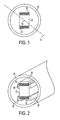
- the comer fibers 15 of a ribbon stack 10 are located furthest from the geometrical center 14 of the fiber ribbon stack 10. Consequently, the comer fibers 15 are subjected to maximum stresses under bending conditions and contact stresses from surrounding components such as a buffer tube 20 housing the ribbon stack 10 and an outer jacket (not shown) surrounding the buffer tube 20, in central tube single-ribbon configurations.
- the corner fibers 15 are subjected to maximum stresses resulting in fiber deformation and consequently, attenuation of the corner fibers 15. It is believed that attenuation is caused by the reduction in the radius of the fiber curvature.
- One of the criterion utilized to predict performance of an optical fiber cable is the stress state of the comer fibers.
- Another criterion is the tensile and compressive windows showing how much displacement under tension and thermal contraction is allowed for the fibers inside the buffer tube before the fiber hits the buffer tube wall.
- design for cables including ribbon stacks is commonly focused on providing a sufficiently large gap or separation distance between the comers of the fiber stack and other structural members such as the wall of the buffer tube in order to avoid or delay contact and bending of the comer fibers which lead to the attenuation problems. Therefore, in conventional cable designs which attempt to prevent possible attenuation problems, the diameter of the buffer tube containing the ribbon stacks may be increased resulting in an undesirable increase in the overall cable diameter.
- the present invention is adapted to achieve the foregoing objects.
- the present invention provides an optical fiber cable comprising an optical fiber ribbon stack including a plurality of optical fibers, and a plurality of cushion members disposed on outer side surfaces of the optical fiber ribbon stack.
- the cushion members function as spacers and strain energy absorbing members for protecting comer fibers of the optical fiber ribbon stack from bending and contact stresses.
- the cushion members have material characteristics, such as contact hardness and Young's modulus, which are similar to those of the ribbon stack, in particular, ribbon matrix. Further, the material characteristics of the cushion members may be graded or gradually change from a soft inner layer at the sides of the cushion members which contact the ribbon stack to a stiff outer layer at the sides of the cushion which may contact the buffer tube or other surrounding elements. When the cushion members contact the sides of the buffer tube under crushing and transverse impact loading conditions, the cushion members are deformed thereby effectively absorbing strains and stresses and protecting the comer fibers of the ribbon stack.
- an elastic membrane surrounding the optical fiber ribbon stack and attached cushion members, and a filler material disposed in the space between the ribbon stack and the elastic membrane and the space between the elastic membrane and the buffer tube.
- the filler material may include a soft polymer, as well as bubbled foam or foamed gel with or without reused materials such as chips or powder of a low-density polyethylene and other non-metals and metals.
- the elastic membrane and the filler material provide a surface for permitting the sliding of the components in the longitudinal direction of the optical cable so that less strain energy is transmitted from the buffer tubes to the fibers under thermally induced contraction, longitudinal bending or buckling of fibers.
- the optical fiber cable includes an optical fiber ribbon stack 10 surrounded by a buffer tube 20.
- a plurality of cushion members 30, in the form of elongated strips, threads, rods or small-diameter tubes, are attached to the sides of the ribbon stack 10 at locations near or overtop the comer edges of the ribbon stack 10.
- the cushion members serve as spacers and strain energy absorbing members which protect comer fibers 15 located at the edges of the ribbon stack 10 from bending and contact stresses.
- the cushion members 30 may have a composite structure formed of multiple laminated layers so that the material characteristics of the cushion members 30 may be graded or gradually change from a soft inner layer at the sides of the cushion members 30 which contact the ribbon stack 10 to a stiff outer layer at the sides of the cushion members 30 which may contact the buffer tube 20 or other surrounding elements.
- outer layer of the cushion members 30 facing the inner wall of the buffer tube 20 may have Young's modulus of about 200 to 300 kg/mm 2 . In other words, the material characteristics of the cushion members 30 gradually change across the width of the cushion members 30.
- the corner fibers 15 press first against the cushion members 30 which are softer than or the same stiffness as the ribbon stack 10. Since the comer fibers 15 do not initially contact the buffer tube wall, the cushion members 30 first act as continuation of the fiber-friendly matrix material of the ribbon stack 10. Next, when the cushion members 30 contact the buffer tube wall, the cushion members are subjected to further deflection and compression with gradually increasing stiffness. As a result, the cushion members 30 function as a spring or a shock absorber, wherein the resistance increases with the applied load.
- the cushion members 30 may be attached to the sides of the ribbon stack 10 at locations next to the edges of the ribbon stack 10, over the edges of the ribbon stack 10, and/or centered at the midpoint point of the sides of the ribbon stack 10. Centering the cushion members 30 in the middle of the sides of the ribbon stack 10 provides the additional advantages of not increasing the overall diameter of the optical cable and providing structural stability to the ribbon stack 10. In particular, in the case of the ribbon stack 10 having a cross-sectional rectangular shape, the centering of the cushion members 30 on the sides of the ribbon stack 10 provides additional structural stability by holding together the individual ribbons which form the ribbon stack 10.
- the cushion members 30 may be twisted together with the ribbon stack 10 to improve structural stability of the ribbon stack 10 (especially in the case of a cable having high number of ribbons per stack) and overall strength and robustness of the optical cable.
- the ribbon stack 10 may be twisted and the cushions members 30 may be twisted with the same twist laylength to follow the stack path and to keep the same position with respect to the cross section of the ribbon stack 10.
- the cushion members 30 may have different cross-sectional shape configurations such as, for example, a rectangular shape 3A, a trapezoidal shape 3B, a hollow tube shape 3C, and circular or oval shape 3D.
- the cross section of the cushion members 30 have a trapezoidal shape 36.
- the hollow tube shape 32 provides an additional cushioning benefit due to the radial or transversal flexibility.
- solid circular or oval rods 38 and rectangular tapes 34 are easier to manufacture than the other shapes thereby reducing associated manufacturing costs.
- the cushion members 30 When the cushion members 30 contact the sides of the buffer tube 20 under crushing and transverse impact loading conditions, the cushion members 30 are deformed thereby effectively absorbing strains and stresses and protecting the comer fibers 15 of the ribbon stack 10. It follows that the deformation of the cushion members 30 on the sides of the ribbon stack 10 under the action of external thermo-mechanical loads will depend on the shape of the cushion cross-section. Further, by positioning the cushion members 30 near the edges of the ribbon stack 10, an arch-like protective structure may be formed above the comers when neighboring cushion members 30 located on perpendicular sides of the ribbon stack 10 deform due to contact with the buffer tube 20, as shown in Figure 4.
- a second embodiment of the present invention will now be described with reference to Figure 5.
- the optical fiber ribbon stack 10 with attached cushion members 30 is surrounded by a thin elastic membrane 40.
- a filler material 50 such as a bubbled foam or foamed gel, is provided in the space between the ribbon stack 10 with attached cushion members 30 and the elastic membrane 40 and in the space between the elastic membrane 40 and the buffer tube 20.
- the elastic membrane 40 is formed of a flexible rubber-like elastomer material such as polyurethane, silicone, styrene-butadiene-rubber, natural rubber (polyisoprene), and acrylonitrile-butadiene-styrene (ABS).
- the elastic membrane 40 serves to hold the cushion members 30 and the ribbon stack 10 and to accommodate a portion of stresses caused by bending, thermal shrinking and contraction.
- the elastic membrane 40 imposes radial compression on the cushion members 30 and the ribbon stack 10 so that the cushion members 30 will be slightly compressed against the ribbon stack 10.
- the elastic membrane 40 provides additional stack integrity or stack stability, especially for tall ribbon stacks.
- the elastic membrane 40 is filled with the filler material 50 to increase sliding with respect to shrinkage and expansion of the outer jacket and to smooth stress distribution.
- the elastic membrane 40 aided by the filler material 50, provides a surface for permitting the sliding of the components in the longitudinal direction of the optical cable. As a result, less strain energy will be transmitted from deforming buffer tube 20 to the optical fibers of the ribbon stack 10 under thermally induced shrinkage or bending.
- the elastic membrane 40 may be manufactured as a second inner buffer tube.
- a very thin thermoplastic (or rubber-like) tube may be extruded over the ribbon stack 10 with attached cushion members 30 and the space between the thin-walled tube (i.e., the elastic membrane 40) and the ribbon stack 10 may be filled with the filler material 50.
- a buffer tube 20 may be extruded around the thin-walled tube and space between the buffer tube 20 and the thin-walled tube is filled with a filler material 50.
- the filler material 50 includes a soft polymer, as well as bubbled foam or foamed gel with or without reused materials such as chips or powder of a low-density polyethylene and other non-metals and metals.
- the filler material can be a gel with small suspended particles.
- the filler material 50 in the form of bubble foam or foamed gel and other bubbled materials with low yield stress and high compressibility (due to easy-to-compress air bubbles or other soft encapsulated materials), provides additional protection under excessively high load by deforming to absorb the load.
- the compressibility of bubbles containing gas or other soft materials contributes to the dissipation of stresses propagating from buffer tube 20 to the fibers of the ribbon stack 10. In this manner, the strain-dissipating properties of the filler material 50 is similar to that of packaging materials such as bubble wrap and styrofoam pieces.
- a loose tube cable 100 includes a plurality of buffer tubes 20 stranded around a central strength member 60.
- a binder 90 is stranded around the buffer tubes 20 and a water-swellable tape 80 is wrapped around each of the buffer tubes 20 in order to reduce contact stresses from expansion and shrinkage of an outer jacket 110.
- the filler material 50 such as bubble foam, is used to fill the space between the cable components in order to maintain the round shape of the cable 100.
- the present invention is clearly applicable to slotted core cables which may or may not include buffer tubes surrounding the ribbon stacks. That is, the ribbon stacks with attached cushion members may be disposed in the grooves or slots of the slotted rod-like core without utilizing a buffer tube. Further, a single tube-like cushion member which completely surrounds and is attached to all sides of the ribbon stack may be utilized rather than a plurality of cushion members individually attached to the sides of the ribbon stack. Accordingly, persons skilled in the art will recognize that many variations of the teachings of this invention can be practiced that still fall within the claims of this invention which follow.
Landscapes
- Physics & Mathematics (AREA)
- General Physics & Mathematics (AREA)
- Optics & Photonics (AREA)
- Insulated Conductors (AREA)
- Laying Of Electric Cables Or Lines Outside (AREA)
- Buffer Packaging (AREA)
- Communication Cables (AREA)
- Light Guides In General And Applications Therefor (AREA)
- Yarns And Mechanical Finishing Of Yarns Or Ropes (AREA)
- Cable Accessories (AREA)
Abstract
Description
Claims (32)
- An optical fiber cable, comprising:an optical fiber ribbon stack comprising a plurality of optical fibers held together in a planar array; andat least one cushion member disposed on an outer side surface of the optical fiber ribbon stack.
- The optical fiber cable as claimed in claim 1, further comprising a buffer tube surrounding the cushion member and the optical fiber ribbon stack.
- The optical fiber cable as claimed in claim 2, further comprising a plurality of cushion members disposed on outer side surfaces of the optical fiber ribbon stack.
- The optical fiber cable as claimed in claim 3, wherein the cushion members are disposed over comer edges of the ribbon stack.
- The optical fiber cable as claimed in claim 3, wherein the cushion members are centered on the outer side surfaces of the ribbon stack.
- The optical fiber cable as claimed in claim 1, wherein the cushion member has an elasticity stiffriess which varies across the thickness of the cushion members.
- The optical fiber cable as claimed in claim 1, wherein the cushion members are disposed along edges of the optical fiber ribbon stack.
- The optical fiber cable as claimed in claim 1, wherein the optical fibers of the optical fiber ribbon stack are held together by a matrix material, and an outer surface of the cushion member has a contact hardness and a Young's modulus which are approximately the same as a contact hard hardness and a Young's modulus of the matrix material.
- The optical fiber cable as claimed in claim 1, wherein the cushion member has a graded contact hardness or Young's modulus which changes from a side of the cushion member which contacts the optical fiber ribbon stack to a side of the cushion member which faces away from the optical fiber ribbon stack.
- The optical fiber cable as claimed in claim 2, wherein the cushion member has a graded Young's modulus or contact hardness which changes from the Young's modulus or contact hardness of the optical fiber ribbon stack towards the Young's modulus and contact hardness of the buffer tube.
- The optical fiber cable as claimed in claim 2, wherein a contact hardness of the cushion member on a side of the cushion member which contacts the optical fiber ribbon stack is a softer than a contact hardness of the cushion member on a side of the cushion member which faces the buffer tube.
- The optical fiber cable as claimed in claim 1, wherein the cushion member is centered on the side surfaces of the optical fiber ribbon stack.
- The optical fiber cable as claimed in claim 1, wherein the cushion member is twisted together with the optical fiber ribbon stack.
- The optical fiber cable as claimed in claim 1, wherein a cross-sectional shape of the cushion member is a hollow tube, a rectangle, a trapezoid, or a circle.
- An optical fiber cable, comprising:an optical fiber ribbon stack comprising a plurality of optical fibers held together in a planar array;at least one cushion member disposed on an outer side surface of the optical fiber ribbon stack;an elastic membrane surrounding the optical fiber stack and the cushion member; anda filler material provided in the space between the optical fiber ribbon stack and the elastic membrane.
- The optical fiber cable as claimed in claim 15, further comprising a buffer tube surrounding the elastic member, wherein the filler material is further provided between the buffer tube and the optical fiber ribbon stack.
- The optical fiber cable as claimed in claim 15, wherein the elastic membrane imposes radial compression on the cushion member, and the optical fiber ribbon stack so that the cushion member is slightly compressed against the optical fiber ribbon stack.
- The optical fiber cable as claimed in claim 17, wherein the elastic membrane is formed of a flexible elastomer material.
- The optical fiber cable as claimed in claim 15, wherein filler material comprises a gel or foam containing a plurality of gaseous bubbles.
- The optical fiber cable as claimed in claim 15, wherein the filler material comprises be a gel with suspended particles.
- The optical fiber cable as claimed in claim 15, wherein the cushion member has an elasticity stiffness which varies across the thickness of the cushion member.
- The optical fiber cable as claimed in claim 15, wherein the cushion member is disposed over edges of the optical fiber ribbon stack.
- The optical fiber cable as claimed in claim 15, wherein an outer surface of the cushion member has a contact hardness and a Young's modulus which are approximately the same as the contact hard hardness and Young's modulus of a matrix material which holds the optical fibers of the optical fiber ribbon stack together in the planar array.
- The optical fiber cable as claimed in claim 15, wherein the cushion member has a graded contact hardness or Young's modulus which changes from sides of the cushion members which contact the ribbon stack towards sides of the cushion members which face away from the ribbon stack.
- The optical fiber cable as claimed in claim 16, wherein the cushion member has a graded Young's modulus or contact hardness which changes from the Young's modulus or contact hardness of the ribbon stack towards the Young's modulus and contact hardness of the buffer tube.
- The optical fiber cable as claimed in claim 15, wherein the cushion member is centered on the side surfaces of the ribbon stack.
- The optical fiber cable as claimed in claim 15, wherein the cushion member is twisted together with the ribbon stack.
- The optical fiber cable as claimed in claim 15, wherein a cross-sectional shape of the cushion member is a hollow tube, a rectangle, a trapezoid, or a circle.
- The optical fiber cable as claimed in claim 16, further comprising a plurality of cushion members disposed on outer side surfaces of the optical fiber ribbon stack.
- The optical fiber cable as claimed in claim 28, wherein the cushion members are disposed over comer edges of the ribbon stack.
- The optical fiber cable as claimed in claim 28, wherein the cushion members are centered on the outer side surfaces of the ribbon stack.
- The optical fiber cable as claimed in claim 28, wherein a contact hardness of the cushion member on a side of the cushion member which contacts the optical fiber ribbon stack is a softer than a contact hardness of the cushion member on a side of the cushion member which faces the buffer tube.
Applications Claiming Priority (2)
| Application Number | Priority Date | Filing Date | Title |
|---|---|---|---|
| US09/972,902 US6749446B2 (en) | 2001-10-10 | 2001-10-10 | Optical fiber cable with cushion members protecting optical fiber ribbon stack |
| US972902 | 2001-10-10 |
Publications (2)
| Publication Number | Publication Date |
|---|---|
| EP1302796A1 true EP1302796A1 (en) | 2003-04-16 |
| EP1302796B1 EP1302796B1 (en) | 2005-03-09 |
Family
ID=25520271
Family Applications (1)
| Application Number | Title | Priority Date | Filing Date |
|---|---|---|---|
| EP02021814A Expired - Lifetime EP1302796B1 (en) | 2001-10-10 | 2002-09-27 | Optical fiber cable with protection system for optical fiber ribbon stack |
Country Status (7)
| Country | Link |
|---|---|
| US (1) | US6749446B2 (en) |
| EP (1) | EP1302796B1 (en) |
| JP (1) | JP2003121711A (en) |
| CN (1) | CN100520467C (en) |
| AT (1) | ATE290701T1 (en) |
| DE (1) | DE60203152T2 (en) |
| ES (1) | ES2238533T3 (en) |
Cited By (9)
| Publication number | Priority date | Publication date | Assignee | Title |
|---|---|---|---|---|
| WO2004061866A3 (en) * | 2002-12-19 | 2004-09-16 | Corning Cable Sys Llc | Optical tube assembly having a dry insert and methods of making the same |
| US7177507B2 (en) | 2002-12-19 | 2007-02-13 | Corning Cable Systems, Llc | Optical tube assembly having a dry insert and methods of making the same |
| US7254302B2 (en) | 2002-12-19 | 2007-08-07 | Corning Cable Systems, Llc. | Optical tube assembly having a dry insert and methods of making the same |
| US7277615B2 (en) | 2002-12-19 | 2007-10-02 | Corning Cable Systems, Llc. | Fiber optic cable having a dry insert and methods of making the same |
| US7336873B2 (en) | 2002-12-19 | 2008-02-26 | Corning Cable Systems, Llc. | Optical tube assembly having a dry insert and methods of making the same |
| US7349607B2 (en) | 2001-06-20 | 2008-03-25 | Corning Cable Systems Technology Incorporated | Optical transmission element |
| US7471861B2 (en) | 2001-06-20 | 2008-12-30 | Corning Cable Systems Llc | Optical transmission element |
| US7471862B2 (en) | 2002-12-19 | 2008-12-30 | Corning Cable Systems, Llc | Dry fiber optic cables and assemblies |
| US7693375B2 (en) | 2002-12-19 | 2010-04-06 | Corning Cable Systems Llc | Fiber optic cable having a dry insert |
Families Citing this family (115)
| Publication number | Priority date | Publication date | Assignee | Title |
|---|---|---|---|---|
| US20030032146A1 (en) * | 2001-07-10 | 2003-02-13 | Dwulet Francis Edward | Enzyme/tag binding and detection system |
| KR100396281B1 (en) * | 2001-08-28 | 2003-09-02 | 삼성전자주식회사 | Loose tube optical ribbon cable |
| US7415181B2 (en) * | 2005-07-29 | 2008-08-19 | Corning Cable Systems Llc | Fiber optic cables and assemblies for fiber to the subscriber applications |
| DE102005001670B3 (en) * | 2005-01-13 | 2006-08-24 | CCS Technology, Inc., Wilmington | Fire-resistant cable and method of making such a cable |
| US7158712B2 (en) * | 2005-05-06 | 2007-01-02 | Coretech Optical Co., Ltd. | Optical fiber coupler and manufacturing apparatus and method thereof |
| US7742667B2 (en) * | 2005-06-08 | 2010-06-22 | Commscope, Inc. Of North Carolina | Fiber optic cables and methods for forming the same |
| US8992098B2 (en) * | 2005-06-08 | 2015-03-31 | Commscope, Inc. Of North Carolina | Methods for forming connectorized fiber optic cabling |
| US10578812B2 (en) | 2005-06-08 | 2020-03-03 | Commscope, Inc. Of North Carolina | Methods for forming connectorized fiber optic cabling |
| US7537393B2 (en) * | 2005-06-08 | 2009-05-26 | Commscope, Inc. Of North Carolina | Connectorized fiber optic cabling and methods for forming the same |
| US7567739B2 (en) * | 2007-01-31 | 2009-07-28 | Draka Comteq B.V. | Fiber optic cable having a water-swellable element |
| US7515795B2 (en) | 2005-07-20 | 2009-04-07 | Draka Comteq B.V. | Water-swellable tape, adhesive-backed for coupling when used inside a buffer tube |
| US7599589B2 (en) * | 2005-07-20 | 2009-10-06 | Draka Comteq B.V. | Gel-free buffer tube with adhesively coupled optical element |
| DE602006020127D1 (en) * | 2006-07-19 | 2011-03-31 | Draka Comteq Bv | Fiber optic cable and method of modification |
| US7406232B2 (en) * | 2006-08-31 | 2008-07-29 | Corning Cable Systems Llc | Non-round fiber optic cable having improved major axis crush resistance |
| US7466888B2 (en) * | 2006-09-12 | 2008-12-16 | Draka Comteq Bv | Filler ribbons for ribbon stack |
| US7639915B2 (en) | 2007-06-28 | 2009-12-29 | Draka Comteq B.V. | Optical fiber cable having a deformable coupling element |
| US7724998B2 (en) * | 2007-06-28 | 2010-05-25 | Draka Comteq B.V. | Coupling composition for optical fiber cables |
| US7646952B2 (en) * | 2007-06-28 | 2010-01-12 | Draka Comteq B.V. | Optical fiber cable having raised coupling supports |
| US8031997B2 (en) * | 2007-11-09 | 2011-10-04 | Draka Comteq, B.V. | Reduced-diameter, easy-access loose tube cable |
| US8081853B2 (en) * | 2007-11-09 | 2011-12-20 | Draka Comteq, B.V. | Single-fiber drop cables for MDU deployments |
| US8145026B2 (en) * | 2007-11-09 | 2012-03-27 | Draka Comteq, B.V. | Reduced-size flat drop cable |
| DK2206001T3 (en) * | 2007-11-09 | 2014-07-07 | Draka Comteq Bv | Optical fiber resistant to microbending |
| US8041167B2 (en) * | 2007-11-09 | 2011-10-18 | Draka Comteq, B.V. | Optical-fiber loose tube cables |
| US8600206B2 (en) * | 2008-11-07 | 2013-12-03 | Draka Comteq, B.V. | Reduced-diameter optical fiber |
| US8041168B2 (en) * | 2007-11-09 | 2011-10-18 | Draka Comteq, B.V. | Reduced-diameter ribbon cables with high-performance optical fiber |
| US8467650B2 (en) * | 2007-11-09 | 2013-06-18 | Draka Comteq, B.V. | High-fiber-density optical-fiber cable |
| US8165439B2 (en) * | 2007-11-09 | 2012-04-24 | Draka Comteq, B.V. | ADSS cables with high-performance optical fiber |
| FR2929716B1 (en) * | 2008-04-04 | 2011-09-16 | Draka Comteq France Sa | OPTICAL FIBER WITH DISPERSION OFFSET. |
| FR2930997B1 (en) | 2008-05-06 | 2010-08-13 | Draka Comteq France Sa | OPTICAL FIBER MONOMODE |
| FR2931253B1 (en) * | 2008-05-16 | 2010-08-20 | Draka Comteq France Sa | FIBER OPTIC TELECOMMUNICATION CABLE |
| FR2932932B1 (en) * | 2008-06-23 | 2010-08-13 | Draka Comteq France Sa | MULTIPLEX WAVE LENGTH OPTIC SYSTEM WITH MULTIMODE OPTIC FIBERS |
| FR2933779B1 (en) * | 2008-07-08 | 2010-08-27 | Draka Comteq France | MULTIMODE OPTIC FIBERS |
| US7970247B2 (en) * | 2008-09-12 | 2011-06-28 | Draka Comteq B.V. | Buffer tubes for mid-span storage |
| FR2938389B1 (en) * | 2008-11-07 | 2011-04-15 | Draka Comteq France | MULTIMODE OPTICAL SYSTEM |
| DK2187486T3 (en) * | 2008-11-12 | 2014-07-07 | Draka Comteq Bv | Reinforcing optical fiber and method of manufacture |
| FR2939246B1 (en) * | 2008-12-02 | 2010-12-24 | Draka Comteq France | AMPLIFIER OPTICAL FIBER AND METHOD OF MANUFACTURE |
| FR2939522B1 (en) * | 2008-12-08 | 2011-02-11 | Draka Comteq France | OPTICAL FIBER AMPLIFIER RESISTANT TO IONIZING RADIATION |
| US8649644B2 (en) * | 2008-12-11 | 2014-02-11 | Corning Cable Systems Llc | Cable jacket with variable perimeter bond |
| FR2939911B1 (en) * | 2008-12-12 | 2011-04-08 | Draka Comteq France | SOLDERED OPTICAL FIBER, TELECOMMUNICATION CABLE COMPRISING MULTIPLE OPTICAL FIBERS AND METHOD FOR MANUFACTURING SUCH A FIBER |
| NL1036343C2 (en) * | 2008-12-19 | 2010-06-22 | Draka Comteq Bv | METHOD AND APPARATUS FOR MANUFACTURING AN OPTICAL FORM. |
| EP2204681B1 (en) | 2008-12-30 | 2016-03-09 | Draka Comteq B.V. | Optical fibre cable comprising a perforated water-blocking element |
| WO2010077132A1 (en) | 2008-12-31 | 2010-07-08 | Draka Comteq B.V. | Uvled apparatus for curing glass-fiber coatings |
| FR2940839B1 (en) * | 2009-01-08 | 2012-09-14 | Draka Comteq France | INDEX GRADIENT MULTIMODAL OPTICAL FIBER, METHODS FOR CHARACTERIZATION AND MANUFACTURE OF SUCH A FIBER |
| FR2941539B1 (en) * | 2009-01-23 | 2011-02-25 | Draka Comteq France | OPTICAL FIBER MONOMODE |
| FR2941540B1 (en) * | 2009-01-27 | 2011-05-06 | Draka Comteq France | MONOMODE OPTICAL FIBER HAVING ENHANCED EFFECTIVE SURFACE |
| FR2941541B1 (en) * | 2009-01-27 | 2011-02-25 | Draka Comteq France | OPTICAL FIBER MONOMODE |
| US8489219B1 (en) | 2009-01-30 | 2013-07-16 | Draka Comteq B.V. | Process for making loose buffer tubes having controlled excess fiber length and reduced post-extrusion shrinkage |
| US9360647B2 (en) * | 2009-02-06 | 2016-06-07 | Draka Comteq, B.V. | Central-tube cable with high-conductivity conductors encapsulated with high-dielectric-strength insulation |
| FR2942571B1 (en) * | 2009-02-20 | 2011-02-25 | Draka Comteq France | AMPLIFIER OPTICAL FIBER COMPRISING NANOSTRUCTURES |
| FR2942551B1 (en) * | 2009-02-23 | 2011-07-15 | Draka Comteq France | CABLE COMPRISING ELEMENTS TO BE EXTRACTED, METHOD OF EXTRACTING THESE ELEMENTS AND METHOD OF MANUFACTURING THE SAME |
| US8625944B1 (en) | 2009-05-13 | 2014-01-07 | Draka Comteq, B.V. | Low-shrink reduced-diameter buffer tubes |
| US8625945B1 (en) | 2009-05-13 | 2014-01-07 | Draka Comteq, B.V. | Low-shrink reduced-diameter dry buffer tubes |
| FR2946436B1 (en) * | 2009-06-05 | 2011-12-09 | Draka Comteq France | MULTIMODE OPTICAL FIBER WITH LARGE BANDWIDTH WITH AN OPTIMIZED HEAT-SLEEVE INTERFACE |
| US20110026889A1 (en) * | 2009-07-31 | 2011-02-03 | Draka Comteq B.V. | Tight-Buffered Optical Fiber Unit Having Improved Accessibility |
| FR2953605B1 (en) * | 2009-12-03 | 2011-12-16 | Draka Comteq France | MULTIMODE OPTICAL FIBER WITH BROAD BANDWIDTH AND LOW BENDBACK LOSSES |
| FR2949870B1 (en) * | 2009-09-09 | 2011-12-16 | Draka Compteq France | MULTIMODE OPTICAL FIBER HAVING IMPROVED BENDING LOSSES |
| FR2957153B1 (en) * | 2010-03-02 | 2012-08-10 | Draka Comteq France | MULTIMODE OPTICAL FIBER WITH BROAD BANDWIDTH AND LOW BENDBACK LOSSES |
| FR2953030B1 (en) * | 2009-11-25 | 2011-11-18 | Draka Comteq France | MULTIMODE OPTICAL FIBER WITH LARGE BANDWIDTH WITH AN OPTIMIZED HEAT-SLEEVE INTERFACE |
| US9014525B2 (en) | 2009-09-09 | 2015-04-21 | Draka Comteq, B.V. | Trench-assisted multimode optical fiber |
| FR2953606B1 (en) * | 2009-12-03 | 2012-04-27 | Draka Comteq France | MULTIMODE OPTICAL FIBER WITH BROAD BANDWIDTH AND LOW BENDBACK LOSSES |
| FR2953029B1 (en) * | 2009-11-25 | 2011-11-18 | Draka Comteq France | MULTIMODE OPTICAL FIBER WITH LARGE BANDWIDTH WITH AN OPTIMIZED HEAT-SLEEVE INTERFACE |
| US8306380B2 (en) * | 2009-09-14 | 2012-11-06 | Draka Comteq, B.V. | Methods and devices for cable insertion into latched-duct conduit |
| FR2950156B1 (en) * | 2009-09-17 | 2011-11-18 | Draka Comteq France | MULTIMODE OPTIC FIBER |
| FR2950443B1 (en) * | 2009-09-22 | 2011-11-18 | Draka Comteq France | OPTICAL FIBER FOR SUM FREQUENCY GENERATION AND METHOD FOR MANUFACTURING THE SAME |
| US8805143B2 (en) * | 2009-10-19 | 2014-08-12 | Draka Comteq, B.V. | Optical-fiber cable having high fiber count and high fiber density |
| GB0919902D0 (en) * | 2009-11-13 | 2009-12-30 | Qinetiq Ltd | Improvements in fibre optic cables for distributed sensing |
| FR2952634B1 (en) * | 2009-11-13 | 2011-12-16 | Draka Comteq France | RARE EARTH DOPED SILICA FIBER WITH LOW DIGITAL OPENING |
| US9042693B2 (en) * | 2010-01-20 | 2015-05-26 | Draka Comteq, B.V. | Water-soluble water-blocking element |
| EP3399357B1 (en) * | 2010-02-01 | 2024-12-11 | Draka Comteq B.V. | Non-zero dispersion shifted optical fiber having a short cutoff wavelength |
| DK2352047T3 (en) * | 2010-02-01 | 2019-11-11 | Draka Comteq Bv | Non-zero dispersion-switched optical fiber with a large effective area |
| EP2369379B1 (en) * | 2010-03-17 | 2015-05-06 | Draka Comteq B.V. | Fibre optique monomode ayant des pertes par courbures réduites |
| US8693830B2 (en) | 2010-04-28 | 2014-04-08 | Draka Comteq, B.V. | Data-center cable |
| PT2390700T (en) | 2010-05-03 | 2016-10-19 | Draka Comteq Bv | PACKAGED OPTICAL FIBER CABLES |
| DK2388239T3 (en) | 2010-05-20 | 2017-04-24 | Draka Comteq Bv | Curing apparatus using angled UV LEDs |
| US8625947B1 (en) | 2010-05-28 | 2014-01-07 | Draka Comteq, B.V. | Low-smoke and flame-retardant fiber optic cables |
| US8871311B2 (en) | 2010-06-03 | 2014-10-28 | Draka Comteq, B.V. | Curing method employing UV sources that emit differing ranges of UV radiation |
| FR2962230B1 (en) | 2010-07-02 | 2012-07-27 | Draka Comteq France | OPTICAL FIBER MONOMODE |
| US8682123B2 (en) | 2010-07-15 | 2014-03-25 | Draka Comteq, B.V. | Adhesively coupled optical fibers and enclosing tape |
| EP2418183B1 (en) | 2010-08-10 | 2018-07-25 | Draka Comteq B.V. | Method for curing coated glass fibres providing increased UVLED intensitiy |
| US8571369B2 (en) | 2010-09-03 | 2013-10-29 | Draka Comteq B.V. | Optical-fiber module having improved accessibility |
| FR2966256B1 (en) | 2010-10-18 | 2012-11-16 | Draka Comteq France | MULTIMODE OPTICAL FIBER INSENSITIVE TO LOSSES BY |
| US8824845B1 (en) | 2010-12-03 | 2014-09-02 | Draka Comteq, B.V. | Buffer tubes having reduced stress whitening |
| DK2482106T5 (en) | 2011-01-31 | 2014-09-22 | Draka Comteq Bv | Multi-mode fiber |
| FR2971061B1 (en) | 2011-01-31 | 2013-02-08 | Draka Comteq France | BROAD BANDWIDTH OPTICAL FIBER WITH LOW CURB LOSSES |
| WO2012112352A1 (en) * | 2011-02-14 | 2012-08-23 | Adc Telecommunications, Inc. | Fiber optic cable assembly with integral strain relief |
| PT2678728T (en) | 2011-02-21 | 2018-07-05 | Draka Comteq Bv | Fiber Optic Interconnect Cable |
| EP2495589A1 (en) | 2011-03-04 | 2012-09-05 | Draka Comteq B.V. | Rare earth doped amplifying optical fiber for compact devices and method of manufacturing thereof |
| EP2503368A1 (en) | 2011-03-24 | 2012-09-26 | Draka Comteq B.V. | Multimode optical fiber with improved bend resistance |
| EP2506044A1 (en) | 2011-03-29 | 2012-10-03 | Draka Comteq B.V. | Multimode optical fiber |
| EP2518546B1 (en) | 2011-04-27 | 2018-06-20 | Draka Comteq B.V. | High-bandwidth, radiation-resistant multimode optical fiber |
| ES2438173T3 (en) | 2011-05-27 | 2014-01-16 | Draka Comteq Bv | Single mode fiber optic |
| EP2533082B1 (en) | 2011-06-09 | 2013-12-25 | Draka Comteq BV | Single mode optical fiber |
| DK2541292T3 (en) | 2011-07-01 | 2014-12-01 | Draka Comteq Bv | A multimode optical fiber |
| EP2584340A1 (en) | 2011-10-20 | 2013-04-24 | Draka Comteq BV | Hydrogen sensing fiber and hydrogen sensor |
| NL2007831C2 (en) | 2011-11-21 | 2013-05-23 | Draka Comteq Bv | Apparatus and method for carrying out a pcvd deposition process. |
| US9892762B1 (en) | 2011-11-30 | 2018-02-13 | Western Digital Technologies, Inc. | Self retaining elastomeric seal |
| USD795874S1 (en) | 2011-11-30 | 2017-08-29 | Western Digital Technologies, Inc. | Ruggedized enclosure for a data storage device |
| US9994380B1 (en) | 2011-11-30 | 2018-06-12 | Western Digital Technologies, Inc. | Ruggedized enclosure for data storage device |
| US8929701B2 (en) | 2012-02-15 | 2015-01-06 | Draka Comteq, B.V. | Loose-tube optical-fiber cable |
| WO2013160714A1 (en) | 2012-04-27 | 2013-10-31 | Draka Comteq Bv | Hybrid single and multimode optical fiber for a home network |
| CA3178019A1 (en) | 2012-05-02 | 2013-11-07 | Afl Telecommunications Llc | Round and small diameter optical cables with a ribbon-like optical fiber structure |
| US9188754B1 (en) | 2013-03-15 | 2015-11-17 | Draka Comteq, B.V. | Method for manufacturing an optical-fiber buffer tube |
| EP3014324A1 (en) * | 2013-06-28 | 2016-05-04 | Corning Optical Communications LLC | Fiber optic assembly for optical cable |
| JP2015215448A (en) * | 2014-05-09 | 2015-12-03 | 株式会社フジクラ | Fiber optic cable |
| JP6255120B1 (en) * | 2017-02-20 | 2017-12-27 | 株式会社フジクラ | Fiber optic cable |
| US10901165B2 (en) * | 2018-06-01 | 2021-01-26 | Sterlite Technologies Limited | Dry padded optic fiber ribbons for dry optic fiber cable |
| US11262516B2 (en) * | 2018-07-05 | 2022-03-01 | Prysmian S.P.A. | High density optical cables |
| CN109936094B (en) * | 2019-04-16 | 2020-06-23 | 上海闸电东海电力工程有限公司 | Cable protection pipe equipment for power construction |
| US11327260B2 (en) | 2019-07-02 | 2022-05-10 | Corning Research & Development Corporation | Foam for optical fiber cable, composition, and method of manufacturing |
| US12032217B2 (en) * | 2019-08-07 | 2024-07-09 | Sterlite Technologies Limited | Cable with interstitial fillers and edge ribbons |
| US11156792B2 (en) * | 2019-10-01 | 2021-10-26 | Sterlite Technologies Limited | Loose tube cable with embedded strength member |
| CA3184658A1 (en) | 2020-06-30 | 2022-01-06 | Anne Germaine Bringuier | Foamed tube having free space around ribbon stacks of optical fiber cable |
| CN113900199B (en) * | 2021-09-24 | 2023-12-01 | 浙江亘古电缆股份有限公司 | Multilayer protection resistance to compression optical cable |
| CN115903158B (en) * | 2023-01-09 | 2023-08-11 | 江苏中天科技股份有限公司 | Butterfly-shaped band-shaped optical cable |
| CN116107049B (en) * | 2023-04-13 | 2023-06-27 | 江苏中天科技股份有限公司 | All-dry type optical fiber ribbon cable |
Citations (4)
| Publication number | Priority date | Publication date | Assignee | Title |
|---|---|---|---|---|
| EP0676654A2 (en) * | 1994-04-07 | 1995-10-11 | Pirelli Cable Corporation | Optical fiber core and cable with reinforced buffer tube loosely enclosing optical fibers |
| US5621842A (en) * | 1994-09-26 | 1997-04-15 | Alcatel Cable | Optical fiber cable and device for manufacturing a cable of this kind |
| EP1085356A2 (en) * | 1999-09-15 | 2001-03-21 | Lucent Technologies Inc. | Cables with optical fiber ribbon stacks |
| US6284367B1 (en) * | 1996-11-14 | 2001-09-04 | Neptco, Inc. | Process for the preparation of nonwoven water blocking tapes and their use in cable manufacture |
Family Cites Families (26)
| Publication number | Priority date | Publication date | Assignee | Title |
|---|---|---|---|---|
| US3984172A (en) | 1973-10-23 | 1976-10-05 | Bell Telephone Laboratories, Incorporated | Optical fiber transmission medium |
| US4078853A (en) * | 1976-02-25 | 1978-03-14 | Bell Telephone Laboratories, Incorporated | Optical communication cable |
| FR2375609A1 (en) * | 1976-12-21 | 1978-07-21 | Cables De Lyon Geoffroy Delore | METHOD OF MANUFACTURING A MATRIX STRUCTURE FOR AN OPTICAL TELECOMMUNICATION CABLE AND CABLE THUS OBTAINED |
| JPS58150905A (en) * | 1982-03-03 | 1983-09-07 | Nippon Telegr & Teleph Corp <Ntt> | Optical cable unit |
| JPS58211712A (en) * | 1982-06-04 | 1983-12-09 | Nippon Telegr & Teleph Corp <Ntt> | Taped optical fiber core unit |
| US5050959A (en) | 1984-09-10 | 1991-09-24 | Sal Randisi | Fiber optic compositions and method for making thereof |
| JPS62502499A (en) * | 1985-04-10 | 1987-09-24 | アメリカン テレフオン アンド テレグラフ カムパニ− | Optical fiber cable and its manufacturing method |
| US4715677A (en) | 1985-12-24 | 1987-12-29 | Sumitomo Electric Research Triangle, Inc. | Ruggedized optical fiber cable |
| US4770489A (en) | 1986-08-27 | 1988-09-13 | Sumitomo Electric Research Triangle, Inc. | Ruggedized optical communication cable |
| JPH01163710A (en) | 1987-02-25 | 1989-06-28 | Sumitomo Electric Ind Ltd | Optical cable |
| US4852965A (en) * | 1987-02-27 | 1989-08-01 | American Telephone And Telegraph Company At&T Bell Laboratories | Composite service and distribution communications media |
| GB8908446D0 (en) | 1989-04-14 | 1989-06-01 | Bicc Plc | Optical cable |
| US5229851A (en) | 1992-04-02 | 1993-07-20 | Pirelli Cable Corporation | Optical fiber cable with large number of ribbon units containing optical fibers and enclosed in tubes |
| US5243675A (en) | 1992-04-16 | 1993-09-07 | At&T Bell Laboratories | Optical fiber cable which resists damage caused by a hostile environment |
| JP3356808B2 (en) * | 1992-11-16 | 2002-12-16 | 住友電気工業株式会社 | Optical cable |
| ATE189530T1 (en) * | 1992-12-16 | 2000-02-15 | Cit Alcatel | OPTICAL CABLE |
| US5440665A (en) | 1993-04-16 | 1995-08-08 | Raychem Corporation | Fiber optic cable system including main and drop cables and associated fabrication method |
| DE19516970A1 (en) | 1995-05-09 | 1996-11-14 | Siemens Ag | Electric and optical cable filler with max. swelling power if water enters |
| US5517591A (en) | 1995-06-07 | 1996-05-14 | Siecor Corporation | Compact slotted core ribbon cable |
| WO1996042029A1 (en) | 1995-06-08 | 1996-12-27 | The Furukawa Electric Co., Ltd. | Optical fiber cable |
| JPH09243884A (en) * | 1996-03-12 | 1997-09-19 | Nippon Telegr & Teleph Corp <Ntt> | Optical flat cable |
| US5651082A (en) | 1996-06-17 | 1997-07-22 | Siecor Corporation | Optical ribbon cables and stranding method |
| US6052502A (en) | 1997-09-22 | 2000-04-18 | Siecor Corporation | Ribbon optical cable having improved strength |
| US6226431B1 (en) * | 1999-06-29 | 2001-05-01 | Lucent Technology Inc. | Optical fiber cable |
| JP3710040B2 (en) * | 1999-08-31 | 2005-10-26 | 古河電気工業株式会社 | Fiber optic cable |
| US6295401B1 (en) * | 1999-12-21 | 2001-09-25 | Siecor Operations, Llc | Optical fiber ribbon cables |
-
2001
- 2001-10-10 US US09/972,902 patent/US6749446B2/en not_active Expired - Fee Related
-
2002
- 2002-09-26 JP JP2002281016A patent/JP2003121711A/en active Pending
- 2002-09-27 AT AT02021814T patent/ATE290701T1/en not_active IP Right Cessation
- 2002-09-27 DE DE60203152T patent/DE60203152T2/en not_active Expired - Lifetime
- 2002-09-27 ES ES02021814T patent/ES2238533T3/en not_active Expired - Lifetime
- 2002-09-27 EP EP02021814A patent/EP1302796B1/en not_active Expired - Lifetime
- 2002-10-10 CN CNB021475059A patent/CN100520467C/en not_active Expired - Fee Related
Patent Citations (4)
| Publication number | Priority date | Publication date | Assignee | Title |
|---|---|---|---|---|
| EP0676654A2 (en) * | 1994-04-07 | 1995-10-11 | Pirelli Cable Corporation | Optical fiber core and cable with reinforced buffer tube loosely enclosing optical fibers |
| US5621842A (en) * | 1994-09-26 | 1997-04-15 | Alcatel Cable | Optical fiber cable and device for manufacturing a cable of this kind |
| US6284367B1 (en) * | 1996-11-14 | 2001-09-04 | Neptco, Inc. | Process for the preparation of nonwoven water blocking tapes and their use in cable manufacture |
| EP1085356A2 (en) * | 1999-09-15 | 2001-03-21 | Lucent Technologies Inc. | Cables with optical fiber ribbon stacks |
Cited By (17)
| Publication number | Priority date | Publication date | Assignee | Title |
|---|---|---|---|---|
| US7349607B2 (en) | 2001-06-20 | 2008-03-25 | Corning Cable Systems Technology Incorporated | Optical transmission element |
| US7471861B2 (en) | 2001-06-20 | 2008-12-30 | Corning Cable Systems Llc | Optical transmission element |
| US7254302B2 (en) | 2002-12-19 | 2007-08-07 | Corning Cable Systems, Llc. | Optical tube assembly having a dry insert and methods of making the same |
| US7471862B2 (en) | 2002-12-19 | 2008-12-30 | Corning Cable Systems, Llc | Dry fiber optic cables and assemblies |
| WO2004061866A3 (en) * | 2002-12-19 | 2004-09-16 | Corning Cable Sys Llc | Optical tube assembly having a dry insert and methods of making the same |
| US7277615B2 (en) | 2002-12-19 | 2007-10-02 | Corning Cable Systems, Llc. | Fiber optic cable having a dry insert and methods of making the same |
| US7336873B2 (en) | 2002-12-19 | 2008-02-26 | Corning Cable Systems, Llc. | Optical tube assembly having a dry insert and methods of making the same |
| US7177507B2 (en) | 2002-12-19 | 2007-02-13 | Corning Cable Systems, Llc | Optical tube assembly having a dry insert and methods of making the same |
| US6970629B2 (en) | 2002-12-19 | 2005-11-29 | Corning Cable Systems Llc | Optical tube assembly having a dry insert and methods of making the same |
| US7236670B2 (en) | 2002-12-19 | 2007-06-26 | Corning Cable Systems, Llc. | Optical tube assembly having a dry insert and methods of making the same |
| US7693375B2 (en) | 2002-12-19 | 2010-04-06 | Corning Cable Systems Llc | Fiber optic cable having a dry insert |
| US7747117B2 (en) | 2002-12-19 | 2010-06-29 | Corning Cable Systems Llc | Optical tube assembly having a dry insert and methods of making the same |
| US7751666B2 (en) | 2002-12-19 | 2010-07-06 | Corning Cable Systems Llc | Optical tube assembly having a dry insert and methods of making the same |
| US9477057B2 (en) | 2005-07-29 | 2016-10-25 | Corning Optical Communications LLC | Fiber optic cables and assemblies |
| US9482837B2 (en) | 2005-07-29 | 2016-11-01 | Corning Cable Systems Llc | Dry fiber optic cables and assemblies |
| US9494755B2 (en) | 2005-07-29 | 2016-11-15 | Corning Optical Communications LLC | Fiber optic cable assembly |
| US9971101B2 (en) | 2005-07-29 | 2018-05-15 | Corning Optical Communications LLC | Fiber optic cable assembly |
Also Published As
| Publication number | Publication date |
|---|---|
| JP2003121711A (en) | 2003-04-23 |
| DE60203152D1 (en) | 2005-04-14 |
| US20030068147A1 (en) | 2003-04-10 |
| CN100520467C (en) | 2009-07-29 |
| DE60203152T2 (en) | 2006-05-11 |
| CN1412590A (en) | 2003-04-23 |
| ES2238533T3 (en) | 2005-09-01 |
| ATE290701T1 (en) | 2005-03-15 |
| US6749446B2 (en) | 2004-06-15 |
| EP1302796B1 (en) | 2005-03-09 |
Similar Documents
| Publication | Publication Date | Title |
|---|---|---|
| US6749446B2 (en) | Optical fiber cable with cushion members protecting optical fiber ribbon stack | |
| US11656419B2 (en) | High density fiber optic ribbon cable | |
| US5751880A (en) | Optical unit for an optical fiber telecommunications cable, and an optical fiber cable including such a unit | |
| EP1489447B1 (en) | A fiber optic cable having no rigid strength members and a reduced coefficient of thermal expansion | |
| EP0676654B1 (en) | Optical fiber core and cable with reinforced buffer tube loosely enclosing optical fibers | |
| CN1325952C (en) | Fiber cable | |
| CN1030941C (en) | Lightweight Fiber Optic Cable | |
| US6934452B2 (en) | Optical fiber cables | |
| US6421487B1 (en) | Reinforced buffered fiber optic ribbon cable | |
| CA2005114C (en) | All-dielectric optical fiber cable having enhanced fiber access | |
| US6487345B1 (en) | Communication cable having reduced jacket shrinkage | |
| JP2005500564A (en) | Optical fiber cable with optical fiber grouped | |
| CN107076948B (en) | Fiber Optic Cable with Impact Resistant Buffer Tube | |
| KR20030018296A (en) | Loose tube optical ribbon cable | |
| US20030086665A1 (en) | High-fiber-density cable with buffer cells shaped as skewed radial sectors | |
| US6611646B1 (en) | Hybrid strength member for an optical cable | |
| CN219574446U (en) | Bending-resistant multimode optical fiber | |
| US6647188B2 (en) | Optical fiber cable | |
| US11592633B2 (en) | Dual layer buffer tube | |
| WO2026019865A1 (en) | Optical fiber ribbon having a hollow core fiber | |
| JPS60202412A (en) | Structure of optical fiber cable | |
| JP2006071773A (en) | Fiber optic cable | |
| KR100303331B1 (en) | Ribbon type optical cable having central formed core | |
| JP5117312B2 (en) | Slotted rod and slotted optical cable | |
| MXPA96002131A (en) | Grooved nucleus plug cable compa |
Legal Events
| Date | Code | Title | Description |
|---|---|---|---|
| PUAI | Public reference made under article 153(3) epc to a published international application that has entered the european phase |
Free format text: ORIGINAL CODE: 0009012 |
|
| AK | Designated contracting states |
Designated state(s): AT BE BG CH CY CZ DE DK EE ES FI FR GB GR IE IT LI LU MC NL PT SE SK TR |
|
| AX | Request for extension of the european patent |
Extension state: AL LT LV MK RO SI |
|
| 17P | Request for examination filed |
Effective date: 20030820 |
|
| 17Q | First examination report despatched |
Effective date: 20031006 |
|
| AKX | Designation fees paid |
Designated state(s): AT BE BG CH CY CZ DE DK EE ES FI FR GB GR IE IT LI LU MC NL PT SE SK TR |
|
| GRAP | Despatch of communication of intention to grant a patent |
Free format text: ORIGINAL CODE: EPIDOSNIGR1 |
|
| GRAS | Grant fee paid |
Free format text: ORIGINAL CODE: EPIDOSNIGR3 |
|
| GRAA | (expected) grant |
Free format text: ORIGINAL CODE: 0009210 |
|
| RAP1 | Party data changed (applicant data changed or rights of an application transferred) |
Owner name: DRAKA COMTEQ B.V. |
|
| AK | Designated contracting states |
Kind code of ref document: B1 Designated state(s): AT BE BG CH CY CZ DE DK EE ES FI FR GB GR IE IT LI LU MC NL PT SE SK TR |
|
| PG25 | Lapsed in a contracting state [announced via postgrant information from national office to epo] |
Ref country code: TR Free format text: LAPSE BECAUSE OF FAILURE TO SUBMIT A TRANSLATION OF THE DESCRIPTION OR TO PAY THE FEE WITHIN THE PRESCRIBED TIME-LIMIT Effective date: 20050309 Ref country code: CH Free format text: LAPSE BECAUSE OF FAILURE TO SUBMIT A TRANSLATION OF THE DESCRIPTION OR TO PAY THE FEE WITHIN THE PRESCRIBED TIME-LIMIT Effective date: 20050309 Ref country code: SK Free format text: LAPSE BECAUSE OF FAILURE TO SUBMIT A TRANSLATION OF THE DESCRIPTION OR TO PAY THE FEE WITHIN THE PRESCRIBED TIME-LIMIT Effective date: 20050309 Ref country code: CZ Free format text: LAPSE BECAUSE OF FAILURE TO SUBMIT A TRANSLATION OF THE DESCRIPTION OR TO PAY THE FEE WITHIN THE PRESCRIBED TIME-LIMIT Effective date: 20050309 Ref country code: BE Free format text: LAPSE BECAUSE OF FAILURE TO SUBMIT A TRANSLATION OF THE DESCRIPTION OR TO PAY THE FEE WITHIN THE PRESCRIBED TIME-LIMIT Effective date: 20050309 Ref country code: EE Free format text: LAPSE BECAUSE OF FAILURE TO SUBMIT A TRANSLATION OF THE DESCRIPTION OR TO PAY THE FEE WITHIN THE PRESCRIBED TIME-LIMIT Effective date: 20050309 Ref country code: FI Free format text: LAPSE BECAUSE OF FAILURE TO SUBMIT A TRANSLATION OF THE DESCRIPTION OR TO PAY THE FEE WITHIN THE PRESCRIBED TIME-LIMIT Effective date: 20050309 Ref country code: AT Free format text: LAPSE BECAUSE OF FAILURE TO SUBMIT A TRANSLATION OF THE DESCRIPTION OR TO PAY THE FEE WITHIN THE PRESCRIBED TIME-LIMIT Effective date: 20050309 Ref country code: LI Free format text: LAPSE BECAUSE OF FAILURE TO SUBMIT A TRANSLATION OF THE DESCRIPTION OR TO PAY THE FEE WITHIN THE PRESCRIBED TIME-LIMIT Effective date: 20050309 |
|
| REG | Reference to a national code |
Ref country code: GB Ref legal event code: FG4D |
|
| REG | Reference to a national code |
Ref country code: CH Ref legal event code: EP |
|
| REG | Reference to a national code |
Ref country code: IE Ref legal event code: FG4D |
|
| REF | Corresponds to: |
Ref document number: 60203152 Country of ref document: DE Date of ref document: 20050414 Kind code of ref document: P |
|
| PG25 | Lapsed in a contracting state [announced via postgrant information from national office to epo] |
Ref country code: BG Free format text: LAPSE BECAUSE OF FAILURE TO SUBMIT A TRANSLATION OF THE DESCRIPTION OR TO PAY THE FEE WITHIN THE PRESCRIBED TIME-LIMIT Effective date: 20050609 Ref country code: DK Free format text: LAPSE BECAUSE OF FAILURE TO SUBMIT A TRANSLATION OF THE DESCRIPTION OR TO PAY THE FEE WITHIN THE PRESCRIBED TIME-LIMIT Effective date: 20050609 Ref country code: GR Free format text: LAPSE BECAUSE OF FAILURE TO SUBMIT A TRANSLATION OF THE DESCRIPTION OR TO PAY THE FEE WITHIN THE PRESCRIBED TIME-LIMIT Effective date: 20050609 |
|
| REG | Reference to a national code |
Ref country code: ES Ref legal event code: FG2A Ref document number: 2238533 Country of ref document: ES Kind code of ref document: T3 |
|
| PG25 | Lapsed in a contracting state [announced via postgrant information from national office to epo] |
Ref country code: PT Free format text: LAPSE BECAUSE OF FAILURE TO SUBMIT A TRANSLATION OF THE DESCRIPTION OR TO PAY THE FEE WITHIN THE PRESCRIBED TIME-LIMIT Effective date: 20050907 |
|
| REG | Reference to a national code |
Ref country code: CH Ref legal event code: PL |
|
| PG25 | Lapsed in a contracting state [announced via postgrant information from national office to epo] |
Ref country code: CY Free format text: LAPSE BECAUSE OF FAILURE TO SUBMIT A TRANSLATION OF THE DESCRIPTION OR TO PAY THE FEE WITHIN THE PRESCRIBED TIME-LIMIT Effective date: 20050927 Ref country code: IE Free format text: LAPSE BECAUSE OF NON-PAYMENT OF DUE FEES Effective date: 20050927 |
|
| PG25 | Lapsed in a contracting state [announced via postgrant information from national office to epo] |
Ref country code: MC Free format text: LAPSE BECAUSE OF NON-PAYMENT OF DUE FEES Effective date: 20050930 Ref country code: LU Free format text: LAPSE BECAUSE OF NON-PAYMENT OF DUE FEES Effective date: 20050930 |
|
| ET | Fr: translation filed | ||
| PLBE | No opposition filed within time limit |
Free format text: ORIGINAL CODE: 0009261 |
|
| STAA | Information on the status of an ep patent application or granted ep patent |
Free format text: STATUS: NO OPPOSITION FILED WITHIN TIME LIMIT |
|
| 26N | No opposition filed |
Effective date: 20051212 |
|
| REG | Reference to a national code |
Ref country code: IE Ref legal event code: MM4A |
|
| PG25 | Lapsed in a contracting state [announced via postgrant information from national office to epo] |
Ref country code: SE Free format text: LAPSE BECAUSE OF FAILURE TO SUBMIT A TRANSLATION OF THE DESCRIPTION OR TO PAY THE FEE WITHIN THE PRESCRIBED TIME-LIMIT Effective date: 20050609 |
|
| PGFP | Annual fee paid to national office [announced via postgrant information from national office to epo] |
Ref country code: GB Payment date: 20140929 Year of fee payment: 13 Ref country code: ES Payment date: 20140926 Year of fee payment: 13 Ref country code: FR Payment date: 20140917 Year of fee payment: 13 |
|
| PGFP | Annual fee paid to national office [announced via postgrant information from national office to epo] |
Ref country code: IT Payment date: 20140923 Year of fee payment: 13 |
|
| PGFP | Annual fee paid to national office [announced via postgrant information from national office to epo] |
Ref country code: DE Payment date: 20140929 Year of fee payment: 13 |
|
| PGFP | Annual fee paid to national office [announced via postgrant information from national office to epo] |
Ref country code: NL Payment date: 20140926 Year of fee payment: 13 |
|
| REG | Reference to a national code |
Ref country code: DE Ref legal event code: R119 Ref document number: 60203152 Country of ref document: DE |
|
| PG25 | Lapsed in a contracting state [announced via postgrant information from national office to epo] |
Ref country code: IT Free format text: LAPSE BECAUSE OF NON-PAYMENT OF DUE FEES Effective date: 20150927 |
|
| GBPC | Gb: european patent ceased through non-payment of renewal fee |
Effective date: 20150927 |
|
| REG | Reference to a national code |
Ref country code: NL Ref legal event code: MM Effective date: 20151001 |
|
| REG | Reference to a national code |
Ref country code: FR Ref legal event code: ST Effective date: 20160531 |
|
| PG25 | Lapsed in a contracting state [announced via postgrant information from national office to epo] |
Ref country code: DE Free format text: LAPSE BECAUSE OF NON-PAYMENT OF DUE FEES Effective date: 20160401 Ref country code: GB Free format text: LAPSE BECAUSE OF NON-PAYMENT OF DUE FEES Effective date: 20150927 |
|
| PG25 | Lapsed in a contracting state [announced via postgrant information from national office to epo] |
Ref country code: FR Free format text: LAPSE BECAUSE OF NON-PAYMENT OF DUE FEES Effective date: 20150930 Ref country code: NL Free format text: LAPSE BECAUSE OF NON-PAYMENT OF DUE FEES Effective date: 20151001 |
|
| REG | Reference to a national code |
Ref country code: ES Ref legal event code: FD2A Effective date: 20161026 |
|
| PG25 | Lapsed in a contracting state [announced via postgrant information from national office to epo] |
Ref country code: ES Free format text: LAPSE BECAUSE OF NON-PAYMENT OF DUE FEES Effective date: 20150928 |