EP1302661A2 - Pump utilizing dissimilar materials to compensate for temperature change - Google Patents
Pump utilizing dissimilar materials to compensate for temperature change Download PDFInfo
- Publication number
- EP1302661A2 EP1302661A2 EP02017038A EP02017038A EP1302661A2 EP 1302661 A2 EP1302661 A2 EP 1302661A2 EP 02017038 A EP02017038 A EP 02017038A EP 02017038 A EP02017038 A EP 02017038A EP 1302661 A2 EP1302661 A2 EP 1302661A2
- Authority
- EP
- European Patent Office
- Prior art keywords
- piston
- pump
- sleeve
- barrel
- comprised
- Prior art date
- Legal status (The legal status is an assumption and is not a legal conclusion. Google has not performed a legal analysis and makes no representation as to the accuracy of the status listed.)
- Withdrawn
Links
Images

Classifications
-
- F—MECHANICAL ENGINEERING; LIGHTING; HEATING; WEAPONS; BLASTING
- F04—POSITIVE - DISPLACEMENT MACHINES FOR LIQUIDS; PUMPS FOR LIQUIDS OR ELASTIC FLUIDS
- F04B—POSITIVE-DISPLACEMENT MACHINES FOR LIQUIDS; PUMPS
- F04B1/00—Multi-cylinder machines or pumps characterised by number or arrangement of cylinders
- F04B1/12—Multi-cylinder machines or pumps characterised by number or arrangement of cylinders having cylinder axes coaxial with, or parallel or inclined to, main shaft axis
- F04B1/20—Multi-cylinder machines or pumps characterised by number or arrangement of cylinders having cylinder axes coaxial with, or parallel or inclined to, main shaft axis having rotary cylinder block
- F04B1/2014—Details or component parts
- F04B1/2035—Cylinder barrels
-
- F—MECHANICAL ENGINEERING; LIGHTING; HEATING; WEAPONS; BLASTING
- F04—POSITIVE - DISPLACEMENT MACHINES FOR LIQUIDS; PUMPS FOR LIQUIDS OR ELASTIC FLUIDS
- F04B—POSITIVE-DISPLACEMENT MACHINES FOR LIQUIDS; PUMPS
- F04B1/00—Multi-cylinder machines or pumps characterised by number or arrangement of cylinders
- F04B1/12—Multi-cylinder machines or pumps characterised by number or arrangement of cylinders having cylinder axes coaxial with, or parallel or inclined to, main shaft axis
- F04B1/20—Multi-cylinder machines or pumps characterised by number or arrangement of cylinders having cylinder axes coaxial with, or parallel or inclined to, main shaft axis having rotary cylinder block
- F04B1/2014—Details or component parts
Definitions
- This invention relates generally to variable delivery pumps within hydraulically-actuated systems, and more particularly to a method and structure for compensating for temperature changes in such pumps.
- variable delivery fixed displacement pumps supply pressurized actuation fluid to hydraulically activated systems within the engine.
- high pressure common rail supplies pressurized lubricating oil to a plurality of hydraulically-actuated fuel injectors mounted in a diesel engine.
- the common rail is pressurized by a swash plate type pump that is driven directly by the engine. The rotation of the swash plate causes a plurality of parallel pistons to reciprocate up and down.
- the desired rail pressure is controlled at least partially as a function of the engine's operating condition. At high speeds and loads, the rail pressure is generally desired to be significantly higher than the desired rail pressure when the engine is operating at an idle condition.
- variable delivery fixed displacement pumps such as shown in U.S. Patent No. 6,035,828 issued to Anderson et. al on 14 March 2000, control the pressure within the common rail by controlling the positioning of individual sleeves that are mounted to move on the outer surface of the individual pistons within the pump.
- the individual sleeves When the engine requires a maximum amount of rail pressure, the individual sleeves are positioned such that they block fluid communication between a low pressure area and spill ports defined by the individual pistons.
- the fluid within the pumping chambers of the pistons is pressurized and displaced to the common rail.
- the individual sleeves are positioned such that the spill ports are in fluid communication with the low pressure area.
- the individual sleeves can be positioned at different points along the outer surface of the respective pistons in order to achieve a desired output between maximum and minimum outputs, and hence a desired rail pressure.
- variable delivery fixed displacement pumps controlling rail pressure through the positioning of sleeves have performed well, there is room for improvement.
- the viscosity of the oil increases, requiring increased force to move the sleeve. This reduces the actuator response of the individual sleeves and may result in long cranking cycles or the inability to start the vehicle or machinery.
- Engineers have address this problem by widening the clearance between the individual sleeves and the pistons in order to reduce the oil sheared between the piston and the individual sleeve while the parts more relative to one another. By widening the clearance, less force is required to move the sleeve and actuator response increases.
- the viscosity of the oil decreases, requiring less force to move the individual sleeves.
- the present invention is directed to one or more of the problems set forth above.
- a pump in one aspect of the present invention, includes a pump housing defining an inlet and an outlet and in which a barrel is at least partially positioned. At least one piston reciprocates in the pump housing and is at least partially positioned in the barrel. A moveable sleeve surrounds an annular outer surface of each piston. At least one of the sleeve and the barrel is made of a material with a lower coefficient of thermal expansion than the material out of which the piston is made.
- there is a method of compensating for temperature change within a pump When the temperature within the pump is low, the clearance between an annular outer surface of a piston and at least one of an inner surface of a sleeve and a barrel is increased. When the temperature within the pump is high, the clearance between the annular outer surface of the piston and at least one of the inner surface of the sleeve and the barrel is decreased.
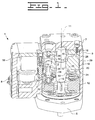
- Pump 1 includes a housing 3 that includes a front flange 5 and an end cap 7. Housing 3 defines and inlet 8 and at least one high pressure outlet 29. The inlet 8 is fluidly connected to a low pressure area 35.
- drive shaft 9 is preferably connected with a wobble type drive plate 12 in a keyway drive configuration in which a key fits into a drive shaft slot 15 and a drive plate slot in drive plate 12. While a keyway drive configuration that allows drive plate 12 to rotate in a non-rigid manner is preferred, it should be appreciated that other configurations are possible.
- a barrel assembly 18 consisting of a barrel 19 and a pressure sealing collar 16 is bolted to the end cap 7 and defines the central shaft bore 13 having a centerline 11.
- the barrel 19 is at least partially positioned in the pump housing 3 and preferably defines a plurality of parallel piston bores 25, which surround the central shaft bore 13 and open into a high pressure area 28, preferably a ring shaped collector cavity.
- the high pressure area 28 is preferably closed from central shaft bore 13 by a pressure sealing collar 16.
- the barrel 19 and the collar 16 are preferably composed of identical materials so that the barrel 19 and the collar 16 have the same thermal expansion when they are heated during manufacturing of the barrel assembly 18. However, it should be appreciated that the barrel 19 and the collar 16 could be made from different materials, so long as the materials utilized have suitable coefficients of thermal expansion.
- the barrel 19 and the bearing collar 16 are comprised of identical substantially homogeneous metallic alloys, such as rod stock or process steel. It should be appreciated that the barrel assembly 18 could be machined from a material other than a substantially homogeneous metallic alloy.
- the barrel 19 is comprised of ceramic, which has a lower coefficient of thermal expansion than steel and can be subjected to high pressures and harsh debris with minimal wear on the barrel 19. Barrel 19 could also be machined from a casting.
- At least one piston 20 is positioned adjacent to the barrel 19 and is slideably received within the respective piston bore 14, such that it can reciprocate between an advanced and retracted position.
- the present invention will be described for one piston 20, it should be appreciated that there are preferably a plurality of pistons 20 positioned within the barrel assembly 18 that are arranged around the centerline 11 and are oriented parallel to the centerline 11. It should be appreciated that any number of pistons 20 may be used within the pump 1, and the present invention operates in the same manner for each piston 20.
- the piston 20 is connected to a respective piston shoe 22 by means of a flexible joint, a ball joint 23 for example, so that the piston shoe 22 can conform to the slanted drive surface of the drive plate 12 as it rotates.
- the rotation of the drive plate 12 causes the piston 20 to reciprocate between the advanced and retracted positions.
- the piston 20 defines a pumping chamber 34 in which the low pressure hydraulic fluid can be pressurized by the reciprocating piston 20.
- a one way outlet check valve 26 is positioned on a top end of the piston 20 to allow pressurized hydraulic fluid to flow into the high pressure area 28 for output from pump 1 and to a common rail via one or more of the high pressure outlets 29.
- the piston 20 is slideably positioned within a sleeve 24 that is attached to a connector 53.
- At least one spill port 30 is defined by each piston 20 to be in close proximity to the respective sleeve 24.
- Spill port 30 is a portion of an internal passage 42 that opens through the side surface of the piston 20.
- the pump 1 is considered a variable delivery pump because the amount of high pressure hydraulic fluid supplied to the common rail of the hydraulic system via the outlet passages 29 varies on the positioning of the respective sleeves 24 surrounding an annular outer surface 21 of each piston 20.
- An electro-hydraulic control unit 32 controls the vertical position of the sleeve 24 about its respective piston 20. The electro-hydraulic control until 32 controls the discharge of pump 1 by selectively allowing the sleeve 24 to cover or uncover spill ports 30 during a variable portion of piston 20 is compression stroke.
- the electro-hydraulic control unit 32 is used to control the positioning of the sleeve 24, it should be appreciated that other types of actuators could be used to control the positioning of the sleeve 24.
- the sleeve 24 has an inner surface 25 and surrounds the annular outer surface 21 of each piston 20.
- the annular outer surface 21 of the piston 20 and the inner surface 25 of the sleeve 24 define a clearance 37.
- the size of the clearance 37 varies with temperature change within the pump 1.
- the clearance 37 is small when the temperature within the pump 1 is high, and the clearance 37 is large when the temperature within the pump 1 is low.
- the clearance 37 is in fluid communication with the low pressure area 35 and the pumping chamber 34.
- the pumping chamber 34 of each piston 20 defines the internal passage 42 extending between a pressure face end 43 of the piston 20 and its annular outer surface 21.
- the sleeve 24 is movable between a first and second position by the electro-hydraulic unit 32.
- the height of the individual sleeve 24 is preferably about equal to the fixed reciprocation distance 45 of the piston 20.
- the electro-hydraulic control unit 32 may move the sleeve 24 to any position between the first position, in which there is maximum output of pressurized hydraulic fluid, and the second position, in which there is virtually no output of pressurized hydraulic fluid.
- the sleeve 24 is biased to its first position. It should be appreciated that the present invention could be applied to a pump in which the sleeves 24 are biased to their second position and virtually none of the actuation fluid is being compressed and delivered to the common rail via the high pressure outlets 29.
- the pumping chamber 34 is substantially blocked from the low pressure area 35 because the only fluid communications are via the clearances 37 between the inner surfaces 25 of the sleeve 24 and barrel 19 and the outer surface 21 of the piston 20.
- the piston 20 and at least one of the sleeve 24 and the barrel 19 are comprised of dissimilar materials.
- the piston 20 is preferably comprised of steel, although it should be appreciated that the piston 20 could be comprised of another material, including a substantially homogeneous metallic alloy.
- the sleeve 24 is comprised of a material with a lower coefficient of thermal expansion than the metal, preferably steel, comprising the piston 20.
- the sleeve 24 is preferably composed of ceramic, which has a lower coefficient of thermal expansion than steel and has a high resistibility to wear cause by the particles in the hydraulic fluid and high pressure.
- the coefficient of thermal expansion of ceramic is approximately 80% of the coefficient of thermal expansion of steel.
- the sleeve 24 and the piston 20 can be comprised of similar materials, while the barrel 19 and the piston 20 are comprised of dissimilar materials.
- the barrel 19 can be composed of a material with a lower coefficient of thermal expansion than the material comprising the piston 20.
- the piston 20 is preferably composed of processed steel, and the barrel 19 is preferably composed of ceramic. Again, the ceramic has a coefficient of thermal expansion which is approximately 80% of the coefficient of thermal expansion of the steel.
- the present invention uses ceramic because it has a lower coefficient of thermal expansion than steel of the piston 20 and a high resistance to wear, any suitable material with a lower coefficient than that material comprising the piston may be used.
- hydraulic fluid flows via the inlet 8 of pump 1 to the low pressure area 35.
- the low pressure area 35 is in fluid communication with the clearance 37 defined by the inner surface 25 of the sleeve 24 and the annular outer surface 21 of the piston 20.
- the sleeve 24 will be in its first, or biased, position in which the spill ports 30 are covered. Virtually all the hydraulic fluid is being pressurized and delivered to the common rail of the hydraulic system.
- the electronic control module will communicate to the electro-hydraulic unit 32 that the pressure within the common rail must be increased in order to start the engine.
- the electro-hydraulic unit 32 will maintain the sleeve 24 via the connector 53 in its first position, at which the sleeve 24 covers the spill ports 30 and substantially blocks fluid communication between the spill ports 30 and the low pressure area 35. Only when the sleeve 24 is in the first position and the piston 20 is in its advanced position will pressure build within the piston 20 allowing the hydraulic fluid to be pressurized in the pumping chamber 34. The pressurized hydraulic fluid will be delivered to the high pressure area 28 past the outlet control valve 26. The high pressure hydraulic fluid will then be delivered to the common rail via the outlet passages 29.
- the electro-hydraulic unit 32 supplies a predetermined control force in order to move the sleeve 24 between its first and second positions.
- the present invention compensates for the temperature change within the pump 1 and the resulting viscosity changes in the hydraulic fluid by varying the size of the clearance 37.
- the piston 20 is preferably comprised of metal, such as steel, and the sleeve 24 is preferable composed of ceramic. Because the ceramic of the sleeve 24 has a coefficient of thermal expansion that is about 80% of the coefficient of thermal expansion of the steel of the piston 20, the steel of the piston 20 will expand more than the ceramic of the sleeve 24 when the pump 1 temperature increases and contract more than the ceramic of the sleeve 24 when the pump 1 temperature decreases. The size of the clearance 37 will change with the temperature within the pump 1.
- the piston 20 and its respective sleeve 24 can be fabricated such that clearance 37 between the inner surface 25 of the sleeve 24 and the annular outer surface 21 of the piston 20 is the appropriate size for hydraulic fluid to move the sleeves efficiently at low temperatures, yet limit leakage through the clearance 37 at high temperatures.
- the steel of the piston 20 will contract more than the ceramic of the sleeve 24, causing the size of the clearance 37 between the annular outer surface 21 of the piston 20 and the inner surface 25 of the sleeve 24 to increase.
- the diameter of the clearance 37 will be approximately 10-20 microns.
- the elector-hydraulic unit 32 will be able to move the sleeve 24 through the high viscous hydraulic fluid without delay.
- the sleeve 24 will block fluid communication between the pumping chamber 34 and the low pressure area 35, causing pressure to build within the pumping chamber 34 and allowing the reciprocating piston 20 to pressurize the hydraulic fluid.
- the hydraulic fluid will then be delivered past the outlet control valve 26 to the high pressure area 28 and out the pump 1 via one of the high pressure outlets 29.
- both the ceramic of the sleeve 24 and the steel of the piston 20 will expand, and the hydraulic fluid will become less viscous. Because the ceramic of the sleeve 24 has a coefficient of thermal expansion about 80% of the coefficient of thermal expansion of the steel of the piston 20, the ceramic of the sleeve 24 will expand less than the steel of the piston 20. Thus, as the temperature increases, the diameter of the annular outer surface 21 of the piston 20 will increase more than the diameter of the inner surface 25 of the sleeve 24, causing the size of the clearance 37 to decrease. Recalling that the size of the clearance 37 could be for example, as large as 20 microns at cold temperatures, the size of the clearance 37 preferably will be approximately, for one example, 8 microns at warm temperatures.
- the size of the clearance 37 may vary over 100% between cold and warm temperatures.
- the electro-hydraulic unit 32 When the pump 1 is activated and temperature within the pump 1 is high, the electro-hydraulic unit 32 will move the sleeve 24 from its second, biased position toward its first position in which the spill ports 30 are covered. Because the clearance 37 decreases as the temperature within the pump 1 increases, the decreased clearance 37 will compensate for the less viscous hydraulic fluid.
- the elector-hydraulic unit 32 will be able to move the positioning of the sleeve 24 with the least amount of leakage and the most efficiency. Because the pumping chamber 34 will be blocked from fluid communication with the low pressure area 35, pressure will build within the pumping chamber 34 and the reciprocating piston 20 will efficiently pressurize the hydraulic fluid. The pressurized hydraulic fluid will be delivered to the common rail via the high pressure outlets 29.
- the desired pressure within the common rail will be varied depending on speed and load. At high speeds and loads, the pressure within the common rail is generally desired to be significantly higher than the desired pressure when the engine is idling. Therefore, the electronic control module will continue to communicate to the electro-hydraulic unit 32 to change the positioning of the sleeves 24 in order to achieve the varying desired rail pressure. Further, as the engine continues working, the hydraulic fluid will continue to warm and become less vicious, and the clearance 37 between the piston 20 and the sleeve 24 will decrease due to the thermal expansion difference between the ceramic of the sleeve 24 and the steel of the piston 20. The continued movement of the sleeves 24 between the first and second positions will be enhanced by the decreased clearance 37.
- the temperature change within the pump 1 can be compensated for by comprising the piston 20 and the barrel 19 of dissimilar materials.
- the piston 20 is positioned within the piston bore 14 of the barrel 19 and is adjacent to the barrel 19.
- the piston 20 will expand more than the barrel 19 at warm temperatures causing a decrease in the clearance between the piston 20 and barrel 19, and the piston 20 will contract more than the barrel 19 at cold temperatures causing an increase in the clearance 37 making pump operation easier at low temperatures, yet reducing inefficiency from leakage at high temperatures.
- the piston 20 is preferably comprised of steel.
- the barrel 19 is preferably comprised of ceramic, although it is appreciated that the barrel 19 could be comprised of any material that has a lower coefficient of thermal expansion than steel. Further, it should be appreciated, that the barrel 19, alone, could be comprised of ceramic, or the barrel assembly 18, including the barrel 19 and the pressure sealing collar 16, could be comprised of ceramic.
- the clearance 37 will decrease allowing more volumetric efficiency. As the temperature within the pump 1 decreases and the viscosity of the hydraulic fluid increases, the clearance 37 will increase allowing a faster actuator response time and easier pumping action.
- the present invention is advantageous because it reduces the need to compromise exceptional performance at any pump 1 temperature in order to have acceptable performance at high and low pump temperatures.
- the size of the clearance 37 varies with the temperature change within the pump 1 and the viscosity change within the hydraulic fluid.
- the clearance 37 decreases to reduce high viscosity hydraulic fluid flow thorough the clearance 37 without reducing the speed at which the electro-hydraulic unit 32 moves the sleeve 24 between the first and second position.
- the clearance 37 increases to allow the electro-hydraulic unit 32 to move the sleeve 24 between its first and second position with the greatest efficiency while maintaining only a small amount of leakage.
- the present invention is advantageous because it compensates for the temperature change within the pump 1 and the viscosity change within the hydraulic fluid without changing the design of the pump 1.
- at least one of the sleeve 24 and the barrel 19 is comprised of a material with a lower coefficient of thermal expansion than the material comprising the piston 20.
- at least one of the sleeve 24 and the barrel 19 is comprised of ceramic.
Landscapes
- Engineering & Computer Science (AREA)
- Mechanical Engineering (AREA)
- General Engineering & Computer Science (AREA)
- Details Of Reciprocating Pumps (AREA)
- Reciprocating Pumps (AREA)
Abstract
Description
Claims (20)
- A pump (1) comprising:a pump housing (3) defining an inlet (8) and an outlet (29);a barrel (19) at least partially positioned in the housing (3);at least one piston (20) that reciprocates in the pump housing (3) and is positioned at least partially in the barrel (19);a sleeve (24) surrounding an annular outer surface (21) of each piston (20) and being movable; andat least one of the barrel (19) and the sleeve (24) being comprised of a material with a lower coefficient of thermal expansion than a material comprising the piston (20).
- The pump (1) of claim 1 wherein a clearance (37) between the annular outer surface (21) of the piston (20) and the inner surface (25) of the sleeve (24) is small when the temperature within the pump (1) is high; and
the clearance (37) between the annular outer surface (21) of the piston (20) and the inner surface (25) of the sleeve (24) is large when the temperature within the pump (1) is low. - The pump (1) of claim 2 wherein the sleeve (24) is comprised of a material with a smaller coefficient of thermal expansion than the material comprising the piston (20).
- The pump (1) of claim 3 wherein the sleeve (24) is comprised of ceramic.
- The pump (1) of claim 4 wherein the piston (20) is comprised of steel.
- The pump (1) of claim 2 wherein the barrel (19) is comprised of a material with a smaller coefficient of thermal expansion than the material comprising the piston (20).
- The pump (1) of claim 6 wherein the barrel (19) is comprised of ceramic.
- The pump (1) of claim 7 wherein the piston (20) is comprised of steel.
- The pump (1) of claim 2 wherein the clearance (37) being a fluid connection between a low pressure area (35) and a pumping chamber (34).
- The pump (1) of claim 9 wherein the pumping chamber (34) includes the piston (20) defining an internal passage (42) extending between a pressure face end (43) and a side surface (21); and
the sleeve (24) being movable between a first position in which the internal passage (42) is substantially blocked from fluid communication with the low pressure area (35), and a second position in which the internal passage (42) is in fluid communication with the low pressure area (35). - The pump (1) of claim 10 wherein the sleeves (24) are movable between the first position and the second position by an actuator (32).
- The pump (1) of claim 11 wherein the sleeve (24) is biased to the first position.
- The pump (1) of claim 12 wherein the sleeve (24) is comprised of ceramic; and
the piston (20) is comprised of steel. - The pump (1) of claim 12 wherein the barrel (19) is comprised of ceramic; and
the piston (20) is comprised of steel. - A method of compensating for temperature change within a pump (1) comprising the steps of:increasing a clearance (37) between an annular outer surface (21) of a piston (20) and at least one of an inner surface (25) of a sleeve (24) and a barrel (19) when a temperature within the pump (1) is low; anddecreasing the clearance (37) between the annular outer surface (21) of the piston (20) and at least one of an inner surface (25) of the sleeve (24) and the barrel (19) when the temperature within the pump (1) is high.
- The method of claim 15 including a step of utilizing at least one of the sleeve (24) and the barrel (19) comprised of a material with a lower coefficient of thermal expansion than a material comprising the piston (20).
- The method of claim 16 including a step of utilizing a sleeve (24) comprised of a material that has a smaller coefficient of thermal expansion than a material comprising the piston (20).
- The method of claim 17 wherein the steps of utilizing includes a step of comprising the sleeve (24) of ceramic; and
comprising the piston (20) of steel. - The method of claim 16 including a step of utilizing a barrel (19) comprised of a material that has a smaller coefficient of thermal expansion than the material comprising the piston (20).
- The method of claim 19 wherein the step of utilizing includes a step of comprising the barrel (19) of ceramic; and
comprising the piston (20) of steel.
Applications Claiming Priority (2)
| Application Number | Priority Date | Filing Date | Title |
|---|---|---|---|
| US974289 | 2001-10-10 | ||
| US09/974,289 US6648605B2 (en) | 2001-10-10 | 2001-10-10 | Pump utilizing dissimilar materials to compensate for temperature change |
Publications (2)
| Publication Number | Publication Date |
|---|---|
| EP1302661A2 true EP1302661A2 (en) | 2003-04-16 |
| EP1302661A3 EP1302661A3 (en) | 2009-09-02 |
Family
ID=25521855
Family Applications (1)
| Application Number | Title | Priority Date | Filing Date |
|---|---|---|---|
| EP02017038A Withdrawn EP1302661A3 (en) | 2001-10-10 | 2002-07-29 | Pump utilizing dissimilar materials to compensate for temperature change |
Country Status (2)
| Country | Link |
|---|---|
| US (1) | US6648605B2 (en) |
| EP (1) | EP1302661A3 (en) |
Cited By (1)
| Publication number | Priority date | Publication date | Assignee | Title |
|---|---|---|---|---|
| WO2006094990A1 (en) * | 2005-03-11 | 2006-09-14 | Innas Bv | Variable pump or hydraulic motor |
Families Citing this family (6)
| Publication number | Priority date | Publication date | Assignee | Title |
|---|---|---|---|---|
| US6802697B2 (en) * | 2002-12-30 | 2004-10-12 | Caterpillar Inc | Variable-delivery, fixed-displacement pump |
| JP2006022785A (en) * | 2004-07-09 | 2006-01-26 | Toyota Industries Corp | Variable displacement compressor |
| WO2007094833A1 (en) * | 2006-02-14 | 2007-08-23 | Battelle Memorial Institute | Accurate metering system |
| US10309380B2 (en) | 2011-11-16 | 2019-06-04 | Ocean Pacific Technologies | Rotary axial piston pump |
| US10094364B2 (en) | 2015-03-24 | 2018-10-09 | Ocean Pacific Technologies | Banded ceramic valve and/or port plate |
| US10184462B2 (en) * | 2015-11-06 | 2019-01-22 | Caterpillar Inc. | Drive assembly and pump assembly arrangement for cryogenic pump |
Family Cites Families (13)
| Publication number | Priority date | Publication date | Assignee | Title |
|---|---|---|---|---|
| US2139387A (en) * | 1935-12-03 | 1938-12-06 | Carter Carburetor Corp | Accelerating pump |
| US2393544A (en) * | 1943-08-05 | 1946-01-22 | Bendix Aviat Corp | Fuel injection pump |
| US3084633A (en) * | 1957-09-09 | 1963-04-09 | North American Aviation Inc | Hydraulic pump or motor |
| US3236189A (en) * | 1962-11-09 | 1966-02-22 | Bank Monticello State | Variable delivery piston pump |
| JPS58172478A (en) * | 1982-04-02 | 1983-10-11 | Mitsubishi Heavy Ind Ltd | Hydraulic machine |
| US4741254A (en) * | 1986-06-12 | 1988-05-03 | Taylor Julian S | Pump plunger |
| GB9416783D0 (en) * | 1994-08-19 | 1994-10-12 | Microhydraulics Inc | Variable delivery pump with spill control |
| US5581881A (en) * | 1994-10-17 | 1996-12-10 | Caterpillar Inc. | Method of making a cylinder barrel having ceramic bore liners |
| US6171070B1 (en) * | 1997-05-09 | 2001-01-09 | Hakusu Tech Co., Ltd. | High-pressure reciprocating pumps |
| US6035828A (en) | 1998-03-11 | 2000-03-14 | Caterpillar Inc. | Hydraulically-actuated system having a variable delivery fixed displacement pump |
| JPH11353616A (en) * | 1998-06-11 | 1999-12-24 | Tdk Corp | Thin-film magnetic head and its production |
| JP2001050137A (en) * | 1999-08-06 | 2001-02-23 | Mitsubishi Electric Corp | Fuel supply pump |
| JP3717731B2 (en) * | 1999-12-13 | 2005-11-16 | カルソニックコンプレッサー株式会社 | Variable capacity gas compressor |
-
2001
- 2001-10-10 US US09/974,289 patent/US6648605B2/en not_active Expired - Fee Related
-
2002
- 2002-07-29 EP EP02017038A patent/EP1302661A3/en not_active Withdrawn
Cited By (3)
| Publication number | Priority date | Publication date | Assignee | Title |
|---|---|---|---|---|
| WO2006094990A1 (en) * | 2005-03-11 | 2006-09-14 | Innas Bv | Variable pump or hydraulic motor |
| EP1705372A1 (en) * | 2005-03-11 | 2006-09-27 | Innas B.V. | Variable pump or hydraulic motor |
| US7967574B2 (en) | 2005-03-11 | 2011-06-28 | Innas B.V. | Variable pump or hydraulic motor |
Also Published As
| Publication number | Publication date |
|---|---|
| EP1302661A3 (en) | 2009-09-02 |
| US20030068243A1 (en) | 2003-04-10 |
| US6648605B2 (en) | 2003-11-18 |
Similar Documents
| Publication | Publication Date | Title |
|---|---|---|
| US6799953B2 (en) | Port plate for an axial piston pump | |
| US6662784B1 (en) | Pump assembly, valve and method | |
| EP2129869B1 (en) | Low leakage plunger assembly for a high pressure fluid system | |
| US5899136A (en) | Low leakage plunger and barrel assembly for high pressure fluid system | |
| EP2169242B1 (en) | Crank mechanism for a reciprocating compressor | |
| US6648605B2 (en) | Pump utilizing dissimilar materials to compensate for temperature change | |
| EP0972936A2 (en) | Positive displacement pumps | |
| US6397796B1 (en) | Oiling systems and methods for changing lengths of variable compression ratio connecting rods | |
| JP2002538355A (en) | Free-piston internal combustion engine with rotating piston | |
| US6622706B2 (en) | Pump, pump components and method | |
| US6893228B2 (en) | Axial piston pump with fluid bearing arrangement | |
| JP2001003839A (en) | High pressure fuel pump | |
| US5295797A (en) | Radial piston pump | |
| US6682315B2 (en) | Axial piston pump barrel with a cast high pressure collection cavity | |
| US6644277B2 (en) | High pressure pump and engine system using the same | |
| US6267561B1 (en) | Variable delivery, fixed displacement pump | |
| US6463903B1 (en) | Piston assembly for free piston internal combustion engine | |
| US6557455B2 (en) | Two piece barrel design for a hydraulic oil pump | |
| US6802697B2 (en) | Variable-delivery, fixed-displacement pump | |
| US6675776B2 (en) | Electro-hydraulic actuator for a hydraulic pump | |
| US6926501B2 (en) | Two-piece swashplate pump housing | |
| EP1264985B1 (en) | Axial piston pump with outer diameter inlet filling |
Legal Events
| Date | Code | Title | Description |
|---|---|---|---|
| PUAI | Public reference made under article 153(3) epc to a published international application that has entered the european phase |
Free format text: ORIGINAL CODE: 0009012 |
|
| AK | Designated contracting states |
Designated state(s): AT BE BG CH CY CZ DE DK EE ES FI FR GB GR IE IT LI LU MC NL PT SE SK TR |
|
| AX | Request for extension of the european patent |
Extension state: AL LT LV MK RO SI |
|
| PUAL | Search report despatched |
Free format text: ORIGINAL CODE: 0009013 |
|
| AK | Designated contracting states |
Kind code of ref document: A3 Designated state(s): AT BE BG CH CY CZ DE DK EE ES FI FR GB GR IE IT LI LU MC NL PT SE SK TR |
|
| AX | Request for extension of the european patent |
Extension state: AL LT LV MK RO SI |
|
| 17P | Request for examination filed |
Effective date: 20091217 |
|
| 17Q | First examination report despatched |
Effective date: 20100119 |
|
| AKX | Designation fees paid |
Designated state(s): DE GB |
|
| STAA | Information on the status of an ep patent application or granted ep patent |
Free format text: STATUS: THE APPLICATION IS DEEMED TO BE WITHDRAWN |
|
| 18D | Application deemed to be withdrawn |
Effective date: 20100601 |