EP1302645A2 - Apparatus and method for controlling the intake air amount of an internal combustion engine - Google Patents
Apparatus and method for controlling the intake air amount of an internal combustion engine Download PDFInfo
- Publication number
- EP1302645A2 EP1302645A2 EP02022801A EP02022801A EP1302645A2 EP 1302645 A2 EP1302645 A2 EP 1302645A2 EP 02022801 A EP02022801 A EP 02022801A EP 02022801 A EP02022801 A EP 02022801A EP 1302645 A2 EP1302645 A2 EP 1302645A2
- Authority
- EP
- European Patent Office
- Prior art keywords
- valve
- target
- air amount
- intake air
- intake
- Prior art date
- Legal status (The legal status is an assumption and is not a legal conclusion. Google has not performed a legal analysis and makes no representation as to the accuracy of the status listed.)
- Withdrawn
Links
- 238000002485 combustion reaction Methods 0.000 title claims abstract description 63
- 238000000034 method Methods 0.000 title claims description 29
- 238000012937 correction Methods 0.000 claims description 80
- 238000011144 upstream manufacturing Methods 0.000 claims description 37
- 230000005540 biological transmission Effects 0.000 claims description 5
- 238000010586 diagram Methods 0.000 description 23
- 238000004364 calculation method Methods 0.000 description 21
- 239000003921 oil Substances 0.000 description 21
- 238000006243 chemical reaction Methods 0.000 description 10
- 239000012530 fluid Substances 0.000 description 7
- 238000003780 insertion Methods 0.000 description 4
- 230000037431 insertion Effects 0.000 description 4
- 101000753286 Homo sapiens Transcription intermediary factor 1-beta Proteins 0.000 description 3
- 102100022012 Transcription intermediary factor 1-beta Human genes 0.000 description 3
- 230000003247 decreasing effect Effects 0.000 description 3
- 238000001514 detection method Methods 0.000 description 3
- 239000000446 fuel Substances 0.000 description 3
- 238000002347 injection Methods 0.000 description 3
- 239000007924 injection Substances 0.000 description 3
- 238000005192 partition Methods 0.000 description 3
- 230000002093 peripheral effect Effects 0.000 description 3
- 238000010926 purge Methods 0.000 description 3
- 230000010485 coping Effects 0.000 description 2
- 238000007599 discharging Methods 0.000 description 2
- 238000012545 processing Methods 0.000 description 2
- 238000013459 approach Methods 0.000 description 1
- 230000015556 catabolic process Effects 0.000 description 1
- 239000003054 catalyst Substances 0.000 description 1
- 238000010276 construction Methods 0.000 description 1
- 239000000498 cooling water Substances 0.000 description 1
- 238000006731 degradation reaction Methods 0.000 description 1
- 230000003111 delayed effect Effects 0.000 description 1
- 230000009977 dual effect Effects 0.000 description 1
- 238000002474 experimental method Methods 0.000 description 1
- 230000002452 interceptive effect Effects 0.000 description 1
- 238000005086 pumping Methods 0.000 description 1
- 238000000746 purification Methods 0.000 description 1
- 230000004044 response Effects 0.000 description 1
- 238000004088 simulation Methods 0.000 description 1
- 230000003068 static effect Effects 0.000 description 1
- 239000010729 system oil Substances 0.000 description 1
- 238000012546 transfer Methods 0.000 description 1
- XLYOFNOQVPJJNP-UHFFFAOYSA-N water Substances O XLYOFNOQVPJJNP-UHFFFAOYSA-N 0.000 description 1
Images


Classifications
-
- F—MECHANICAL ENGINEERING; LIGHTING; HEATING; WEAPONS; BLASTING
- F02—COMBUSTION ENGINES; HOT-GAS OR COMBUSTION-PRODUCT ENGINE PLANTS
- F02D—CONTROLLING COMBUSTION ENGINES
- F02D13/00—Controlling the engine output power by varying inlet or exhaust valve operating characteristics, e.g. timing
- F02D13/02—Controlling the engine output power by varying inlet or exhaust valve operating characteristics, e.g. timing during engine operation
- F02D13/0223—Variable control of the intake valves only
- F02D13/0226—Variable control of the intake valves only changing valve lift or valve lift and timing
-
- Y—GENERAL TAGGING OF NEW TECHNOLOGICAL DEVELOPMENTS; GENERAL TAGGING OF CROSS-SECTIONAL TECHNOLOGIES SPANNING OVER SEVERAL SECTIONS OF THE IPC; TECHNICAL SUBJECTS COVERED BY FORMER USPC CROSS-REFERENCE ART COLLECTIONS [XRACs] AND DIGESTS
- Y02—TECHNOLOGIES OR APPLICATIONS FOR MITIGATION OR ADAPTATION AGAINST CLIMATE CHANGE
- Y02T—CLIMATE CHANGE MITIGATION TECHNOLOGIES RELATED TO TRANSPORTATION
- Y02T10/00—Road transport of goods or passengers
- Y02T10/10—Internal combustion engine [ICE] based vehicles
- Y02T10/12—Improving ICE efficiencies
Definitions
- the present invention relates to a technique for controlling an intake air amount by a variable valve mechanism in an engine, which varies at least an operation characteristic of an intake valve.
- variable valve mechanism constituted to successively vary a valve lift amount and a valve operating angle (refer to Japanese Unexamined Patent Publication 2001-012262).
- variable valve mechanism In an engine provided with such a variable valve mechanism, a valve lift amount and a valve operating angle are controlled by the variable valve mechanism, to control an intake air amount independently of a throttle valve.
- a torque control by the throttle valve cannot be performed, there occurs a problem of how the torque linearity is ensured.
- variable valve mechanism In the case where the intake air amount control is performed by the above variable valve mechanism, it is impossible to generate, in an intake air passage, a negative pressure for the canister purging or the blowby gas processing. Moreover, from such a mechanism, since there is a limitation in controllable valve operating characteristic (valve lift amount and valve operating angle), it becomes necessary to perform a control by the throttle valve in addition to the control by the variable valve mechanism, depending on conditions.
- variable valve timing mechanism (apparatus) that varies "operation timing" of intake valve, and is to control the intake air amount mainly by the throttle valve. Therefore, it cannot be applied to an engine in which the intake air amount is controlled mainly by the variable valve mechanism. The above problem still remains unsolved.
- the present invention has been achieved in view of the above problems and has an object to ensure torque linearity with high accuracy when performing an intake air amount control by a variable valve mechanism.
- a further object of the present invention is to appropriately perform a cooperative control of the variable valve mechanism and a throttle valve so as to enable to cope with the generation of requested negative pressure and the like, while executing the intake air amount control (torque control) mainly by the variable valve mechanism.
- a target intake air amount equivalent to a target torque is set in accordance with operating conditions of the engine, a target valve operating characteristic is set based on the set target intake air amount, and the variable valve mechanism is controlled so that an actual valve operating characteristic reaches the target valve operating characteristic.
- the intake air amount control mainly by the variable valve mechanism can be executed with high accuracy, while ensuring the torque linearity.
- variable valve mechanism is controlled so that the actual valve operating characteristic becomes the target valve operating characteristic, and also a target throttle opening of the throttle valve is set based on the target intake air amount and the valve operating characteristic to control the actuator so that an actual throttle opening reaches the target throttle opening.
- the intake air amount control mainly by the variable valve mechanism and also with the variable valve mechanism cooperated with the throttle valve can be executed.
- the intake air amount control with higher accuracy and also to cope with the negative pressure request and the like.
- Fig. 1 is a view showing a system structure of an internal combustion engine in an embodiment of the present invention.
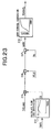
- Fig. 2 is a cross section view showing a variable valve mechanism in the embodiment (A-A cross section view of Fig. 3)
- Fig. 3 is a side elevation view of the variable valve mechanism.
- Fig. 4 is a top plan view of the variable valve mechanism.
- Fig. 5 is a perspective view showing an eccentric cam for use in the variable valve mechanism.
- Fig. 6A and Fig. 6B are cross section views showing an operation of the variable valve mechanism at a low lift condition (B-B cross section view of Fig. 3).
- Fig. 7A and Fig. 7B are cross section views showing an operation of the variable valve mechanism at a high lift condition (B-B cross section view of Fig. 3).
- Fig. 8 is a valve lift characteristic diagram corresponding to a base end face and a cam surface of a swing cam in the variable valve mechanism.
- Fig. 9 is a characteristic diagram showing valve timing and valve lift of the variable valve mechanism.
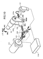
- Fig. 10 is a perspective view showing a rotational driving mechanism of a control shaft in the variable valve mechanism.
- Fig. 11 is a longitudinal section view of a variable valve timing mechanism in the embodiment.
- Fig. 12 is an entire block diagram showing an intake air amount control (torque control) in the embodiment.
- Fig. 13 to Fig. 20 are block diagrams showing the details of intake air amount control in the embodiment, in which:
- Fig. 1 is a structural diagram of an internal combustion engine for vehicle.
- an electronically controlled throttle 104 is disposed for driving a throttle valve 103b to open and close by a throttle motor 103a. Air is sucked into a combustion chamber 106 via electronically controlled throttle 104 and an intake valve 105.
- a combusted exhaust gas is discharged from combustion chamber 106 via an exhaust valve 107, purified by an exhaust purification catalyst 108, and then emitted into the atmosphere via a muffler 109.
- Exhaust valve 107 is driven by a cam 111 axially supported by an exhaust side camshaft 110, while keeping a valve lift amount and a valve operating angle thereof constant.
- the valve lift amount and valve operating angle of intake valve 105 are successively varied by a variable valve mechanism (VEL) 112, and valve timing thereof is successively varied by a variable valve timing mechanism (VTC) 113.
- VTC variable valve timing mechanism
- a control unit (C/U) 114 incorporating therein a microcomputer, controls the drive of electronically controlled throttle 104, variable valve mechanism (VEL) 112 and variable valve timing mechanism (VTC) 113 in accordance with an accelerator opening APO to be detected by an accelerator opening sensor APS 116, so that an intake air amount corresponding to the accelerator opening can be obtained based on an opening of throttle valve 103b and an opening characteristic of intake valve 105.
- throttle valve 103b is controlled so as to generate a constant negative pressure (target Boost) for the canister purging and the blowby gas processing, while controlling the intake air amount by controlling the valve lift amount (and valve operating angle) of variable valve mechanism (VEL) 112.
- target Boost constant negative pressure
- VEL variable valve mechanism
- throttle-less control in which throttle valve 103b is kept full-opened and the intake air amount is controlled only by variable valve mechanism (VEL) 112, is performed.
- throttle valve 103b In the case where the intake air amount cannot be controlled only by variable valve mechanism (VEL) 112, throttle valve 103b is also controlled.
- Control unit (C/U) 114 receives various detection signals from an air flow meter 115 detecting an intake air amount (mass flow) Qa, a crank angle sensor 117 taking out a rotation signal from a crankshaft, a throttle sensor 118 detecting an opening TVO of throttle valve 103b, a water temperature sensor 119 detecting a cooling water temperature Tw of engine 101 and the like, in addition to a detection signal from accelerator opening sensor APS 116.
- an engine rotation speed Ne is calculated based on the rotation signal output from crank angle sensor 117. Further, an electromagnetic fuel injection valve 131 is disposed on an intake port 130 on the upstream side of intake valve 105 of each cylinder. Fuel injection valve 131 injects fuel adjusted at a predetermined pressure toward intake valve 105 when driven to open by an injection pulse signal from control unit (C/U) 114.
- variable valve mechanism (VEL) 112 a structure of variable valve mechanism 112 will be described.
- Fig. 2 to Fig. 4 show in detail the structure of variable valve mechanism (VEL) 112 (however, this merely shows one example, and the present invention is not limited to such a structure).
- VEL variable valve mechanism
- Variable valve mechanism (VEL) 112 shown in Fig. 2 to Fig. 4 includes a pair of intake valves 105, 105, a hollow camshaft (drive shaft) 13 rotatably supported by a cam bearing 14 of a cylinder head 11, two eccentric cams (drive cams) 15, 15 being rotation cams axially supported by a camshaft 13, a control shaft 16 rotatably supported by the same cam bearing 14 at an upper position of camshaft 13, a pair of rocker arms 18, 18 swingingly supported by control shaft 16 through a control cam 17, and a pair of independent swing cams 20, 20 disposed to upper end portions of intake valves 105, 105 through valve lifters 19, 19, respectively.
- Eccentric cams 15, 15 are connected with rocker arms 18, 18 by link arms 25, 25, respectively.
- Rocker arms 18,18 are connected with swing cams 20, 20 by link members 26, 26.
- Rocker arms 18, 18, link arms 25, 25, and link members 26, 26 constitute a transmission mechanism.
- Each eccentric cam 15, as shown in Fig. 5, is formed in a substantially ring shape and includes a cam body 15a of small diameter, a flange portion 15b integrally formed on an outer surface of cam body 15a.
- a camshaft insertion hole 15c is formed through the interior of eccentric cam in an axial direction, and also a center axis X of cam body 15a is biased from a center axis Y of camshaft 13 by a predetermined amount.
- Eccentric cams 15, 15 are pressed and fixed to both outer sides of camshaft 13 via camshaft insertion holes 15c at positions not interfering with valve lifters 19, 19.
- Outer peripheral surfaces 15d, 15d of cam bodies 15a, 15a are formed in the same profile.
- Each rocker arm 18, as shown in Fig. 4, is bent and formed in a substantially crank shape, and a central base portion 18a thereof is rotatably supported by control cam 17.
- a pin hole 18d is formed through one end portion 18b which is formed to protrude from an outer end portion of base portion 18a.
- a pin 21 to be connected with a tip portion of link arm 25 is pressed into pin hole 18d.
- a pin hole 18e is formed through the other end portion 18c which is formed to protrude from an inner end portion of base portion 18a.
- a pin 28 to be connected with one end portion 26a (to be described later) of each link member 26 is pressed into pin hole 18e.
- Control cam 17 is formed in a cylindrical shape and fixed to a periphery of control shaft 16. As shown in Fig. 2, a center axis P1 position of control cam 17 is biased from a center axis P2 position of control shaft 16 by ⁇ .
- Swing cam 20 is formed in a substantially lateral U-shape as shown in Fig. 2, Fig. 6 and Fig. 7, and a supporting hole 22a is formed through a substantially ring-shaped base end portion 22.
- Camshaft 13 is inserted into base end portion 22 to be rotatably supported.
- a pin hole 23a is formed through an end portion 23 positioned at the other end portion 18c of rocker arm 18.
- Base circular surface 24a and cam surface 24b are in contact with a predetermined position of an upper surface of each valve lifter 19 corresponding to a swing position of swing cam 20.
- a predetermined angle range 61 of base circular surface 24a is a base circle interval and a range of from base circle interval 61 of cam surface 24b to a predetermined angle range 62 is a so-called ramp interval, and a range of from ramp interval 62 of cam surface 24b to a predetermined angle range 63 is a lift interval.
- Link arm 25 includes a ring-shaped base portion 25a and a protrusion end 25b protrudingly formed on a predetermined position of an outer surface of base portion 25a.
- a fitting hole 25c rotatably to be fitted with the outer surface of cam body 15a of eccentric cam 15 is formed on a central position of base portion 25a.
- a pin hole 25b into which pin 21 is rotatably inserted is formed through protrusion end 25b.
- Link member 26 is formed in a linear shape of predetermined length and pin insertion holes 26c, 26d are formed through both circular end portions 26a, 26b. End portions of pins 28, 29 pressed into pin hole 18d of the other end portion 18c of rocker arm 18 and pin hole 23a of end portion 23 of swing cam 20, respectively, are rotatably inserted into pin insertion holes 26c, 26d. Snap rings 30, 31, 32 restricting axial transfer of link arm 25 and link member 26 are disposed on respective end portions of pins 21, 28, 29.
- Control shaft 16 is driven to rotate within a predetermined angle range by a DC servo motor (actuator) 121 disposed at one end portion thereof.
- DC servo motor 121 By varying the operating angle of control shaft 16 by DC servo motor 121, the valve lift amount and valve operating angle of each of intake valves 105, 105 are successively varied (refer to Fig. 9).
- DC servo motor 121 is arranged so that the rotation shaft thereof is parallel with control shaft 16, and a bevel gear 122 is axially supported by the tip portion of the rotation shaft.
- a pair of stays 123a, 123b are fixed to the tip portion of control shaft 16.
- a nut 124 is swingingly supported around an axis parallel to control shaft 16 connecting the tip portions of the pair of stays 123a, 123b.
- a bevel gear 126 meshed with bevel gear 122 is axially supported at the tip portion of a threaded rod 125 engaged with nut 124. Threaded rod 126 is rotated by the rotation of DC servo motor 121, and the position of nut 124 engaged with threaded rod 125 is displaced in the axial direction of threaded rod 125, so that control shaft 16 is rotated.
- valve lift amount is decreased as the position of nut 124 approaches bevel gear 126, while the valve lift amount is increased as the position of nut 124 gets away from bevel gear 126.
- a potentiometer type operating angle sensor127 detecting the operating angle of control shaft 16 is disposed on the tip portion of control shaft 16, as shown in Fig. 10.
- Control unit 114 feedback controls DC servo motor (actuator) 121 so that an actual operating angle detected by operating angle sensor 127 coincides with a target operating angle.
- variable valve timing mechanism (VTC) 113 shows in detail the structure of variable valve timing mechanism (VTC) 113. (However, this structure is merely one example, and the present invention is not limited to such a structure). Variable valve timing mechanism (VTC) 113 shown in Fig.
- a vane type variable valve timing mechanism which comprises: a cam sprocket 51 (timing sprocket) which is rotatably driven by a crankshaft 120 via a timing chain; a rotation member 53 secured to an end portion of intake side camshaft 13 and rotatably housed inside cam sprocket 51; a hydraulic circuit 54 that relatively rotates rotation member 53 with respect to cam sprocket 51; and a lock mechanism 60 that selectively locks a relative rotation position between cam sprocket 51 and rotation member 53 at predetermined positions.
- a cam sprocket 51 timing sprocket
- rotation member 53 secured to an end portion of intake side camshaft 13 and rotatably housed inside cam sprocket 51
- a hydraulic circuit 54 that relatively rotates rotation member 53 with respect to cam sprocket 51
- a lock mechanism 60 that selectively locks a relative rotation position between cam sprocket 51 and rotation member 53 at predetermined positions.
- Cam sprocket 51 comprises: a rotation portion (not shown in the figure) having on an outer periphery thereof, teeth for engaging with timing chain (or timing belt); a housing 56 located forward of the rotation portion, for rotatably housing rotation member 53; and a front cover and a rear cover (not shown in the figure) for closing the front and rear openings of housing 56.
- Housing 56 presents a cylindrical shape formed with both front and rear ends open and with four partition portions 63 protrudingly provided at positions on the inner peripheral face at 90° in the circumferential direction, four partition portions 63 presenting a trapezoidal shape in transverse section and being respectively provided along the axial direction of housing 56.
- Rotation member 53 is secured to the front end portion of intake side camshaft 13 and comprises an annular base portion 77 having four vanes 78a, 78b, 78c, and 78d provided on an outer peripheral face of base portion 77 at 90° in the circumferential direction.
- First through fourth vanes 78a to 78d present respective cross-sections of approximate trapezoidal shapes.
- the vanes are disposed in recess portions between each partition portion 63 so as to form spaces in the recess portions to the front and rear in the rotation direction.
- Advance angle side hydraulic chambers 82 and retarded angle side hydraulic chambers 83 are thus formed.
- Lock mechanism 60 has a construction such that a lock pin 84 is inserted into an engagement hole (not shown in the figure) at a rotation position (in the reference operating condition) on the maximum retarded angle side of rotation member 53.
- Hydraulic circuit 54 has a dual system oil pressure passage, namely a first oil pressure passage 91 for supplying and discharging oil pressure with respect to advance angle side hydraulic chambers 82, and a second oil pressure passage 92 for supplying and discharging oil pressure with respect to retarded angle side hydraulic chambers 83.
- a supply passage 93 and drain passages 94a and 94b To these two oil pressure passages 91 and 92 are connected a supply passage 93 and drain passages 94a and 94b, respectively, via an electromagnetic switching valve 95 for switching the passages.
- An engine driven oil pump 97 for pumping oil in an oil pan 96 is provided in supply passage 93, and the downstream ends of drain passages 94a and 94b are communicated with oil pan 96.
- First oil pressure passage 91 is formed substantially radially in a base 77 of rotation member 53, and connected to four branching paths 91d communicating with each advance angle side hydraulic chamber 82.
- Second oil pressure passage 92 is connected to four oil galleries 92d opening to each retarded angle side hydraulic chamber 83.
- an internal spool valve is arranged so as to control the switching between respective oil pressure passages 91 and 92, and supply passage 93 and drain passages 94a and 94b.
- Control unit (C/U) 114 controls the power supply quantity for an electromagnetic actuator 99 that drives electromagnetic switching valve 95, based on a duty control signal superimposed with a dither signal.
- control unit (C/U) 114 that is a control on electronically controlled throttle 104, variable valve mechanism (VEL) 112 and variable valve timing mechanism (VTC) 113 (a first embodiment).
- control unit (C/U) 114 includes a target volume flow ratio calculating section "a”, a VTC target operating angle calculating section "b”, a VEL target operating angle calculating section “c” and a target throttle opening calculating section "d".
- the target volume flow ratio calculating section "a" calculates a target volume flow ratio TQH0ST equivalent to a target torque as follows.
- a requested air amount (a requested engine air amount) Q0 corresponding to accelerator opening APO and engine rotation speed Ne (or, that so as to obtain a target torque set based on accelerator opening APO and engine rotation speed Ne) is calculated, and also a requested ISC air amount QISC requested in an idle rotation speed control (ISC) is calculated.
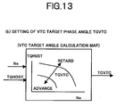
- the VTC target operating angle calculating section "b", as shown in Fig. 13, calculates a target phase angle (TGVTC) of variable valve timing mechanism (VTC) 113, referring to a map as shown in the figure, based on target volume flow ratio TQH0ST and engine rotation speed Ne.
- TSVTC target phase angle
- VTC variable valve timing mechanism
- control unit (C/U) 114 controls variable valve timing mechanism (VTC) 113 so that an actual VTC phase angle reaches the target phase angle (TGVTC).
- the VEL target operating angle calculating section "c” calculates a target operating angle TGVEL (target lift amount) of variable valve mechanism (VEL) 112 so as to ensure target volume flow ratio TQH0ST, as follows.
- target volume flow ratio TQH0ST is (inversely) transformed, to calculate a target valve opening area TVELAA. Then, based on target valve opening area TVELAA, target operating angle TGVEL (target lift amount) of control shaft 16 in variable valve mechanism (VEL) 112 is calculated.
- the target operating angle is set so as to increase the valve lift amount, as target volume flow ratio TQH0ST is larger and also engine rotation speed Ne is higher.
- a throttle control of throttle valve 103b is also performed. Note, in this embodiment, larger the operating angle of control shaft 16 becomes, larger the lift amount of intake valve 105 becomes.
- target volume flow ratio TQH0ST is compared with a minimum volume flow ratio QH0LMT, and a higher one is selected to set a volume flow ratio TQH0VEL to be realized in variable valve mechanism (VEL) 112 (to be referred to as VEL realizing volume flow ratio hereafter).
- minimum volume flow ratio QH0LMT is the one realizable (controllable) by variable valve mechanism (VEL) 112 (that is, the volume flow ratio of when the VEL operating angle is minimum), which is calculated, in "a1" part, by retrieving a table TQH0LMT as shown in the figure, based on engine rotation speed Ne.
- a target valve operating characteristic of variable valve mechanism (VEL) 112 can be set so that an intake air amount control by mainly by variable valve mechanism (VEL) 112 is executed.
- an air flow amount passing through intake valve 105 (that is, a cylinder intake air amount) Qc (t) (kg/sec) can be represented by equations (1), (2) based on an equation of a one-dimensional steady flow of compressed fluid.
- Qc (t) Cd ⁇ Av ⁇ P0 R ⁇ T0 ⁇ 2 ⁇ -1 ⁇ +1 2( ⁇ -1)
- TQH0VEL realizing volume flow ratio
- valve upstream temperature Tm, valve upstream pressure Pm and cylinder pressure Pc have been already known, Cd ⁇ Av/(Ne ⁇ VOL#) is calculated to be converted into A ⁇ Cd/N/V characteristic, so that state amount VACDNV equivalent to valve opening area (Av) can be obtained. Therefore, in this embodiment, a table TVACDN as shown in the figure has been previously prepared, and by retrieving this table, based on VEL realizing volume flow ratio TQH0VEL, the conversion into A ⁇ Cd/N/V characteristic is performed. Note, the table TVACDNV is prepared in the following manner.
- VEL realizing volume flow ratio TQH0VEL can be determined, at the choke time, from the equation (3) as a value corresponding to Cd ⁇ Av/(Ne ⁇ VOL#) and a differential pressure ratio (Pc/P0) between fore and after the intake valve, and can be determined, at the no choke time, from the equation (4) as a value proportional to Cd ⁇ Av/(Ne ⁇ VOL#), the map is prepared by obtaining a correlation between TQH0VEL and Cd ⁇ Av/(Ne ⁇ VOL#) by the simulation, experiment or the like.
- This TVELAA0 corresponds to the opening area basically requested for the intake valve (to be referred to as basic requested valve opening area hereafter).
- a VTC based correction is performed on basic requested valve opening area TVELAA0.
- basic requested valve opening area TVELAA0 is divided by valve timing based correction value KHOSIVC corresponding to closing timing of intake valve, to calculate TVELAA1.
- valve timing based correction value KHOSIVC corresponding to closing timing of intake valve
- TVELAA1 calculated at E part is corrected corresponding to the upstream pressure of intake valve 105 (to be simply referred to as valve upstream pressure hereafter). Specifically, TVELAA1 is multiplied by valve upstream pressure based correction value KMANIP, to calculate TVELAA2. The volume flow ratio is changed due to a negative pressure generated in accordance with throttle opening. The valve opening area corresponding to such a change is obtained.
- TVELAA2 calculated at F part is corrected corresponding to engine rotation speed Ne.
- TVELAA2 is divided by a VEL opening area rotating correction value KHOSNE, to calculate TVELAA.
- VEL variable valve mechanism
- an inertial force is increased due to the increase of engine rotation speed Ne, resulting in that the valve lift amount (valve opening area) is increased by the inertial force even in the same VEL operating angle. Therefore, the increased portion is corrected.
- VEL opening area rotating correction value KHOSNE used for such a correction is calculated by retrieving, at g1 part, a table TKHOSNE as shown in the figure based on engine rotation speed Ne.
- target valve opening area TVELAA is converted into a VEL operating angle TGVEL0.
- TGVEL0 a relation between the valve operating angle (lift amount) and the valve opening area has been previously obtained.
- Target valve opening area TVELAA is calculated as the flow amount characteristic including valve flow loss coefficient Cd, as a matter of form.
- valve flow loss coefficient Cd is determined based on the valve operating angle (lift amount) in this embodiment
- the conversion table TTGVEL0 is set inclusive of valve flow loss coefficient Cd, to directly calculate target valve operating angle TGVEL0 based on the flow amount characteristic equivalent to the valve opening area (that is, target valve opening area TVELAA).
- valve flow loss coefficient Cd may be calculated by retrieving a table TCd based on valve operating angle (VCS-ANGL) (at h1 part), a valve opening area TVELAA' may be calculated by dividing target valve opening area (that is, the flow amount characteristic equivalent to valve opening area) TVELAA by valve flow loss coefficient Cd (at h2 part), and then target operating angle TGVEL0 may be calculated based on valve opening area TVELAA' (h3 part).
- valve flow loss dynamic correction coefficient DHOSCD is calculated by retrieving a table TDHOSCD based on engine rotation speed Ne (at h4 part), to multiply this on TVELAA' (at h5 part). Thereby, valve flow loss coefficient Cd is corrected according to engine rotation speed Ne. Valve flow loss dynamic correction coefficient DHOSCD may be directly multiplied on valve flow loss coefficient Cd.
- VEL operating angle TGVEL0 converted at H part is compared with an upper limit VEL operating angle (upper limit valve operating characteristic) VELHLMT of variable valve mechanism (VEL) 112, to set a target VEL operating angle TGVEL. Specifically, as shown in the figure, if TGVEL0 ⁇ VELHLMT, VELHLMT is set as target VEL operating angle TGVEL. If TGVEL0 ⁇ VELHLMT, TGVEL0 is set as target VEL operating angle TGVEL.
- variable valve mechanism (VEL) 112 since the accuracy of intake air amount control by variable valve mechanism (VEL) 112 is degraded under a state where there is no substantial differential pressure ratio between fore and after the valve (that is, intake valve 105 is almost fully opened), the upper limit value of valve operating characteristic is set to prevent the accuracy degradation and also a valve operating characteristic capable of ensuring the volume efficiency is set as much as possible. Accordingly, upper limit VEL operating angle VELHLMT is set as a maximum operating angle capable of maintaining the accuracy of intake air amount control.
- Maximum VEL operating angle VELHLMT is calculated by retrieving, at i1 part, a table TVELHLMT as shown in the figure based on engine rotation speed Ne.
- control unit (C/U) 114 feedback controls actuator 121, so that an actual VEL operating angle (VCS-ANGL) of control shaft 16 in variable valve mechanism (VEL) 112 reaches target VEL operating angle (TGVEL).
- VCS-ANGL actual VEL operating angle
- valve timing based correction value KHOSIVC to be used at E part in Fig. 14 will be described referring to a control block diagram in Fig. 16.
- an actual IVC angle REALIVC is obtained by subtracting a rotation phase VTCNOW of intake side camshaft 13 from V0IVC.
- a valve timing based correction value KHOSIVC is set to be output to E part in Fig. 14.
- valve timing based correction value KHOSIVC includes: (1) a static correction (correction of decreased portion of effective cylinder volume); (2) a dynamic correction (considering that, during engine rotating, air amount of the effective cylinder equivalent volume at IVC cannot be sucked, the effective cylinder equivalent volume is made variable by the valve lift amount within a range of 0 to 100%); and (3) a correction of valve overlap (the correction corresponding to opening timing IVO of intake valve 105).
- the table TKHOSIVC is set inclusive of the factors of (1) to (3).
- valve upstream pressure based correction value KMANIP to be used at F part in Fig. 14, referring to a control block diagram in Fig. 17.
- Pm0 valve upstream pressure at the time when throttle valve is fully opened (intake manifold pressure substantially equals atmospheric pressure)
- Pm1 valve upstream pressure at the time of target Boost (intake manifold pressure)
- Pc0 valve downstream pressure at the time when throttle valve is fully opened (substantially equals cylinder pressure)
- Pc1 valve downstream pressure at the time of target Boost (substantially equals cylinder pressure)
- Av0 intake valve opening area at the time when throttle valve is fully opened
- Av1 intake valve opening area at the time of target Boost.
- valve upstream pressure based correction value KMANIP relative to valve opening area Av0 at the time when the valve upstream pressure equals the atmospheric pressure (Pm0) is represented by the following equations (7) and (8).
- KMANIP Cd1 ⁇ Av1
- Cd0 ⁇ Av0 Pm0
- Pm1 the atmospheric pressure
- valve upstream pressure based correction value KMANIP is primarily determined by the atmospheric pressure/target Boost (manifold pressure) at the choke time. Further, since it is considered that (Pc0/Pm0) substantially equals (Pc1/Pm1), the atmospheric pressure/target Boost becomes dominative even at no choke time. In either of the cases, valve upstream pressure based correction value KMANIP can be made the atmospheric pressure/target Boost.
- the atmospheric pressure/target Boost target manifold pressure
- KMANIP valve upstream pressure based correction value
- target volume flow TQH0ST is equal to or less than minimum volume flow ratio QH0LMT, that is in the case where minimum volume flow ratio QH0LMT is selected at A part in Fig. 14, regardless of the valve upstream pressure, 1.0 is output as valve upstream pressure based correction value KMANIP so that the valve operating angle equivalent to minimum volume flow ratio QH0LMT can be finally obtained (correction is not performed).
- the intake air amount control is performed by the control of variable valve mechanism (VEL) 112.
- the throttle control is executed.
- the target throttle opening calculating section "c" calculates a target throttle opening TDVTC in the following manner.
- an opening area TVOAA0 of throttle valve 103b required for generating a predetermined negative pressure (to be referred to as standard requested throttle opening area hereafter) is calculated, and corrected in accordance with an actual change in valve operating characteristic of (controlled) intake valve 105, to be made a target throttle opening area TVOAA.
- target throttle opening TDTVO is calculated based on target throttle opening area TVOAA.
- a state amount TADNV0 equivalent to an opening area At of throttle valve 103b requested at the standard valve operating characteristic is calculated.
- TADNV0 is calculated by retrieving a conversion table TTADNV0 as shown in the figure, based on target volume flow ratio TQH0ST.
- calculated TADNV0 is multiplied by engine rotation speed Ne at K part, and further multiplied by discharge amount VOL# at L part, to calculate standard requested throttle opening area TVOAA0.
- a correction according to a change in operating characteristic of intake valve 105 is performed on calculated standard requested throttle opening area TVOAA0.
- standard requested throttle opening area TVOAA0 is multiplied by an intake valve opening based correction value KAVEL, to be made target throttle opening area TVOAA.
- the setting of intake valve opening based correction value KAVEL will be described later (refer to Fig. 19).
- target throttle opening TDTVO is set by retrieving a conversion table TTDTVO as shown in the figure, based on calculated target throttle opening area TVOAA.
- control unit (C/U) 114 controls electronically controlled throttle 104 so that an actual opening of throttle valve 104 becomes target throttle opening TDTVO.
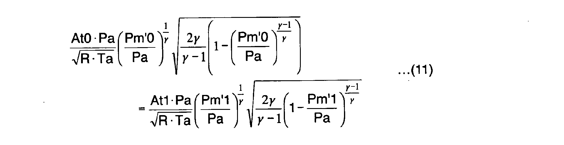
- an air flow amount Qth (t) (kg/sec) passing through throttle valve 103b can be represented by the following equations (9) and (10) from the equation of the one dimensional steady flow of compressed fluid.
- Pc Pm ⁇ 2 ⁇ + 1 ⁇ ⁇ -1 Qth (t) At ⁇ Pa R ⁇ Ta ⁇ 2 ⁇ - 1 ⁇ +1 2( ⁇ -1)
- Pa atmospheric pressure (Pa)
- Pm manifold pressure (Pa)
- Ta outside air temperature
- At throttle opening area (m 2 ).
- Pa atmospheric pressure
- Ta outside air temperature
- Pm'0 intake manifold pressure at standard valve operating characteristic
- Pm'1 intake manifold pressure at the time when variable valve mechanism (VEL) operates
- At0 throttle opening area at standard valve operating characteristic
- At1 throttle opening area at the time when variable valve mechanism (VEL) operates.
- intake valve opening based correction value KAVEL relative to throttle opening area At0 at standard valve operating characteristic is represented by the following equation (12).
- a pressure ratio (Pm'0/Pa) at standard valve operating characteristic is obtained by referring to a map previously allotted in performance as shown in the figure, based on target volume flow ratio TQH0ST and engine rotation speed Ne.
- a coefficient KAP0 is calculated by retrieving a table TBLKAP0 as shown in the figure, based on the pressure ratio (Pm'0/Pa) at standard valve operating characteristic.
- this coefficient KAP0 can be represented by the following equation (13) and corresponds to a value of the numerator in the equation (12).
- a pressure ratio (Pm'1/Pa) at the time when variable valve mechanism (VEL) 112 operates is calculated in the following manner.
- an air amount (actual intake air amount) Qacyl sucked into cylinder can be represented by the following equation (14) assumed that a new air rate is ⁇ .
- Qacyl VOL R ⁇ Ta ⁇ Pm'1
- TP is an air amount (actual intake air amount) Qacyl sucked in the cylinder
- VOL is an effective cylinder volume at each valve operating characteristic of intake valve 105.
- pressure ratio (Pm'1/Pa) can be calculated without the necessity of detecting intake manifold pressure Pm'.
- a conversion constant TPGAIN# is multiplied on a ratio WQH0VEL of volume flow passed through intake valve 105 at each operating characteristic at the time when throttle valve 103b is fully opened, and the unit conversion is performed to calculate TP100V.
- the calculation of ratio WQH0VEL of passed volume flow will be described later (refer to Fig. 20).
- new air rate ⁇ is calculated by referring to a map previously allotted in performance as shown in the figure, based on a ratio RQH0VEL of volume flow passed through intake valve 105 (actual engine volume flow ratio) at each operating characteristic at the time when throttle valve 103b is throttled (at the time when the valve upstream pressure is generated) and engine rotation speed Ne.
- RQH0VEL of volume flow passed through intake valve 105
- the calculation of actual engine volume flow ratio RQH0VEL will be described later (refer to Fig. 20).
- new air rate ⁇ is not limited to the one calculated as above, and may be estimated based on operating conditions, for example.
- pressure ratio (Pm'1/Pa) between manifold pressure and atmospheric pressure can be obtained without the necessity of detecting intake manifold pressure Pm.
- pressure ratio (Pm'1/Pa) may be calculated using a detection value of the pressure sensor.
- a coefficient KAP1 is calculated by retrieving a table TKPA1 as shown in the figure, based on pressure ratio (Pm'1/Pa) at the time when variable valve mechanism (VEL) 112 operates.
- This coefficient KAP1 can be represented by the following equation (16) and corresponds to a value of the denominator in the equation (12).
- an opening area AAVEL0 of intake valve 105 is calculated by retrieving a table TAAVEL0 as shown in the figure, based on operating angle VCS-ANGL of variable valve mechanism (VEL) 112.
- VEL opening area is rotatingly corrected according to engine rotation speed Ne, to calculate AAVEL.
- Calculated AAVEL is divided by engine rotation speed Ne at m12 part, and further divided by discharge amount (cylinder volume) VOL# at m13 part, to be made an A/N/V characteristic.
- a table TWH0VEL0 as shown in the figure is retrieved, to convert the A/N/V characteristic into a volume flow ratio WH0VEL0.
- the VTC based correction is performed to calculate ratio WQH0VEL of volume flow passed through intake valve 105 at the time when throttle valve 103b is fully opened, and the resultant is output to m3 part in Fig. 19.
- AAVEL calculated at m11 part is multiplied by the ratio between actual intake manifold pressure Pm and atmospheric pressure Pa (Pm/Pa), to calculate AAVEL'.
- this AAVEL' is divided by engine rotation speed Ne at m17 part, and further divided by discharge amount (cylinder volume) VOL# at m18 part, to be made the A/N/V characteristic.
- a table TRH0VEL0 as shown in the figure is retrieved to convert the A/N/V characteristic into a volume flow ratio RH0VEL0.
- the VTC based correction is performed to calculate the actual volume flow ratio RQH0VEL, and the resultant is output to m4 part in Fig. 19.
- variable valve mechanism (VEL) 112 and electronically controlled throttle 104 are cooperative with each other. Therefore, an intake air amount control (torque control) mainly by variable valve mechanism (VEL) 112 can be executed with high accuracy.
- intake valve 105 is controlled to a target valve operating characteristic. While, in a total opening area (an integrated value of opening areas) obtained based on the target valve operating characteristic, since the opening area during valve overlap period is an ineffective portion where air is not newly sucked, the total opening area is corrected with a correction value according to the valve overlap to be made a total opening area (effective opening area) where air is newly sucked, so that the total opening area (effective opening area) indicative of intake air amount actually controlled by intake valve is compared with the target intake air amount to set a target opening of throttle valve 103b.
- a total opening area an integrated value of opening areas
- a target volume flow ratio calculating section 301 calculates a target volume flow ratio TQH0ST (target intake air amount) of engine 101, in the same manner as the target volume flow ratio calculating section "a" in the first embodiment.
- a target operating angle TGVEL target lift amount of control shaft 16 in variable valve mechanism (VEL) 112 is calculated by referring to a map as shown in the figure, based on target volume flow ratio TQH0ST and engine rotation speed Ne.
- the target operating angle is set such that the lift amount becomes larger.
- a target phase angle TGVTC (target advance amount) in variable valve timing mechanism (VTC) 113 is calculated based on target volume flow ratio TQH0ST and engine rotation speed Ne.
- the larger target volume flow ratio TQH0ST is and the higher engine rotation speed Ne is, the target valve timing is retarded.
- target operating angle TGVEL is input to a valve total opening area calculating section 304, to be converted into the total opening area of intake valve 105 of when variable valve mechanism (VEL) 112 is controlled based on target operating angle TGVEL.
- the total opening area is an integral value of valve opening area during a closing period of intake valve 105.
- variable valve mechanism (VEL) 112 is controlled based on target operating angle TGVEL, and also opening timing IVO of intake valve 105 assuming that the valve timing is controlled to the most retarded side by variable valve timing mechanism (VTC) 113, is calculated.
- Opening timing IVO calculated in VTC most retarded time IVO calculating section 305 is added with a target phase angle TGVTC by an adder 306. Thereby, opening timing TGIVO of when the operating characteristic of intake valve 105 is controlled based on target operating angle TGVEL and target phase angle TGVTC, is obtained.
- the opening timing TGIVO is input to an O/L time basic area calculating section 307.
- a basic value of opening area integral value of intake valve 105 during the valve overlap period between intake valve 105 and exhaust valve 107 is obtained based on opening timing TGIVO, since the closing timing of exhaust valve 107 is fixed.
- the basic value is obtained in conformity with the case where the valve lift amount is smallest.
- a correction coefficient in order to cope with a difference of opening area due to a difference of lift amount is set based on target operating angle TGVEL.
- correction coefficient ( ⁇ 1.0) is set to be a larger value as the operating angle (lift amount) becomes larger.
- the correction coefficient calculated in O/L time area VEL correctively calculating section 308 is input to a switching output section 309.
- switching output section 309 either the correction coefficient calculated in O/L time area VEL correctively calculating section 308 or 1.0 being a reference value of the correction coefficient is selectively output, depending on whether or not opening timing TGIVO (advance value from top dead center TDC to opening timing IVO) exceeds a predetermined angle (for example, 20 degrees).
- valve overlap period As described above, even if the valve overlap period is the same, the opening area of intake valve 105 during the valve overlap period is changed depending on the lift amount. However, if the valve overlap period is short, there does not occur a large difference in the opening area depending on a difference between the lift amount (refer to Fig. 25).
- the correction coefficient output from switching output section 309 is multiplied on the basic value of opening area integral value of intake valve 105 in the valve overlap period calculated by O/L time basic area calculating section 307.
- the opening area integral value in the valve overlap period being the resultant of multiplicative calculation in adder 310 is subtracted from the total opening area calculated in valve total opening area calculating section 304, and the integral value of opening area in the opening period of intake valve 105 except for the valve overlap period is obtained.
- the calculation result in a subtracter 311 is output to a multiplier 312, wherein the calculation result in subtracter 311 is multiplied by the correction coefficient calculated in a VEL opening area rotating correction calculating section 313, to be output as effective opening area TVELAA0.
- VEL opening area rotating correction calculating section 313 sets a larger correction coefficient (( ⁇ 1.0), as engine rotation speed Ne is higher.
- variable valve mechanism (VEL) 112 As described in the first embodiment, there is a tendency that the valve lift amount becomes larger than a target due to inertial force, as engine rotation speed Ne becomes higher. Due to this, there occurs an error difference between the opening area calculated based on target operating angle TGVEL and target phase angle TGVTC, and the actual opening area. Therefore, in VEL opening area rotating correction calculating section 313, a correction coefficient is set in order to increasingly correct the opening area of intake valve 105 coping with the tendency that the valve lift amount becomes larger than the target, as engine rotation speed Ne is higher.
- a flow loss coefficient Cd is calculated based on target operating angle TGVEL (target valve lift amount).
- Effective opening area TVFELAA0 subjected to the correction by flow loss coefficient Cd is divided by effective discharge amount (cylinder total volume) VOL# in a divider 316, and further divided by engine rotation speed Ne in a divider 317, to be converted into a state amount AANV. Further, state amount AANV is converted into volume flow ratio TQH0VE of intake valve 105 in a conversion section 318.
- volume flow ratio TQH0VEL of intake valve 105 is a value on the condition of the full open state of throttle valve 103b.
- target volume flow ratio TQH0ST is divided by volume flow ratio TQH0VEL, to calculate volume flow ratio QH0 required for throttle valve 103b in order to obtain target volume flow ratio TQH0ST.
- Volume flow ratio QH0 required for throttle valve 103b is converted into state amount AANV in a conversion section 320, and is multiplied by effective discharge amount (cylinder total volume) VOL# in a multiplier 321 and further multiplied by engine rotation speed Ne in a multiplier 322, to be converted into opening area AA required for throttle valve 103b.
- opening area AA is converted into an angle (opening) of throttle valve 103b in a conversion section 323, and the angle is output as target angle TGTVO so that electronically controlled throttle 104 is controlled based on target angle TGTVO.
- volume flow ratio TQH0VEL actually obtained with the lift amount and valve timing of intake valve 105 is converted from the effective opening area (total opening area after correction) of intake valve 105 considering the ineffective opening area during the valve overlap period.
- Target volume flow ratio TQH0ST is divided by volume flow ratio TQH0VEL, to obtain requested volume flow ratio QH0 of throttle valve 103b, and this requested volume flow ratio QH0 is converted into the target opening of throttle valve 103b.
- the valve operating characteristic (lift amount and valve timing) of intake valve 105 is controlled based on the target intake air amount (target volume flow ratio TQH0ST), and also the intake air amount (volume flow ratio) actually obtained with the valve operating characteristic of intake valve 105 is predicted based on the valve overlap, so that the excess portion (error amount due to valve overlap) to the target intake air amount (target volume flow ratio TQH0ST) can be corrected by the throttle control of throttle valve 103b.
- the control to the target intake air amount (target volume flow ratio TQH0ST) can be performed with high accuracy.
Landscapes
- Engineering & Computer Science (AREA)
- Chemical & Material Sciences (AREA)
- Combustion & Propulsion (AREA)
- Mechanical Engineering (AREA)
- General Engineering & Computer Science (AREA)
- Output Control And Ontrol Of Special Type Engine (AREA)
- Electrical Control Of Air Or Fuel Supplied To Internal-Combustion Engine (AREA)
Abstract
Description

At choke:

At choke:

At choke time:


Claims (54)
- An apparatus for controlling an intake air amount of an internal combustion engine provided with a variable valve mechanism that varies at least a valve operating characteristic of an intake valve, comprising:an operating condition detecting sensor detecting operating conditions of said engine;a valve operating characteristic detecting sensor detecting said valve operating characteristic; anda control unit that sets a target intake air amount equivalent to a target torque according to the operating conditions of the engine, sets a target valve operating characteristic based on the set target intake air amount, and controls said variable valve mechanism so that an actual valve operating characteristic reaches said target valve operating characteristic.
- An apparatus for controlling an intake air amount of an internal combustion engine according to claim 1,
wherein said internal combustion engine is provided with a throttle valve driven to open and close by an actuator, in addition to said variable valve mechanism;
said apparatus further comprises a throttle opening sensor detecting an opening of said throttle valve; and
said control unit controls said variable valve mechanism so that the actual valve operating characteristic reaches said target valve operating characteristic, and
sets a target throttle opening of said throttle valve based on said target intake air amount and said valve operating characteristic, to control said actuator so that an actual throttle opening reaches said target throttle opening. - An apparatus for controlling an intake air amount of an internal combustion engine according to claim 1,
wherein said control unit sets said target intake air amount based on an accelerator opening and an engine rotation speed. - An apparatus for controlling an intake air amount of an internal combustion engine according to claim 1,
wherein, when said target intake air amount is equal to or less than a minimum intake air amount controllable by said variable valve mechanism, said control unit sets said target valve operating characteristic based on the minimum intake air amount. - An apparatus for controlling an intake air amount of an internal combustion engine according to claim 4,
wherein said minimum intake air amount is calculated based on an engine rotation speed. - An apparatus for controlling an intake air amount of an internal combustion engine according to claim 1,
wherein said control unit converts a target volume flow ratio equivalent to said target torque into a target valve opening area, and sets said target valve operating characteristic based on the target valve opening area. - An apparatus for controlling an intake air amount of an internal combustion engine according to claim 6,
wherein said control unit corrects said target valve opening area according to the valve operating characteristic, and sets said target valve operating characteristic based on the corrected target valve opening area. - An apparatus for controlling an intake air amount of an internal combustion engine according to claim 7,
wherein said control unit corrects said target valve opening area based on a flow loss amount according to a valve lift amount of said intake valve. - An apparatus for controlling an intake air amount of an internal combustion engine according to claim 8,
wherein said control unit corrects said target valve opening area based on the flow loss amount according to the valve lift amount of said intake valve and also according to an engine rotation speed. - An apparatus for controlling an intake air amount of an internal combustion engine according to claim 7,
wherein said control unit corrects said target valve opening area according to actual closing timing of said intake valve. - An apparatus for controlling an intake air amount of an internal combustion engine according to claim 6,
wherein said control unit corrects said target valve opening area according to an intake pressure on the intake valve upstream side, and sets said target valve operating characteristic based on the corrected target valve opening area. - An apparatus for controlling an intake air amount of an internal combustion engine according to claim 11,
wherein, when said target volume flow ratio is equal to or less than a minimum volume flow ratio controllable by said variable valve mechanism, said control unit does not perform the correction according to the intake pressure on the intake valve upstream side. - An apparatus for controlling an intake air amount of an internal combustion engine according to claim 6,
wherein said control unit corrects said target valve opening area according to an engine rotation speed, and sets said target valve operating characteristic based on the corrected target valve opening area. - An apparatus for controlling an intake air amount of an internal combustion engine according to claim 1,
wherein, when said target valve operating characteristic is equal to or above a predetermined upper limit valve operating characteristic, said control unit controls said variable valve mechanism so that the actual valve operating characteristic reaches said upper limit valve operating characteristic. - An apparatus for controlling an intake air amount of an internal combustion engine according to claim 14,
wherein said upper limit valve operating characteristic is calculated based on an engine rotation speed. - An apparatus for controlling an intake air amount of an internal combustion engine according to claim 2,
wherein said control unit converts said target volume flow ratio equivalent to said target torque into a requested throttle opening area requested for said throttle valve when said intake valve has a standard valve operating characteristic, corrects the requested throttle opening area according to the actual valve operating characteristic, and sets said target throttle opening based on the corrected requested throttle opening area. - An apparatus for controlling an intake air amount of an internal combustion engine according to claim 16,
wherein said control unit corrects said requested throttle opening area based on a correction value calculated based on a ratio between the atmospheric pressure and an intake pressure on the intake valve upstream side of when said intake valve is the standard valve operating characteristic, and a ratio between the atmospheric pressure and an actual intake pressure on the intake valve upstream side. - An apparatus for controlling an intake air amount of an internal combustion engine according to claim 17,
wherein said ratio between the atmospheric pressure and the actual intake pressure on the intake valve upstream side is calculated based on an actual intake air amount sucked into the engine, a throttle full-open time intake air amount sucked into the engine at the time when said throttle valve is fully opened, and a new air rate set according to operating conditions of the engine. - An apparatus for controlling an intake air amount of an internal combustion engine according to claim 2,
wherein said control unit predicts an actual intake air amount controlled by the intake valve based on the operating characteristic of the intake valve and the valve overlap at the operating characteristic, and sets said target throttle opening based on the predicted value and said target intake air amount. - An apparatus for controlling an intake air amount of an internal combustion engine according to claim 2,
wherein said control unit calculates a valve operating area of the intake valve at said target valve operating characteristic, corrects the valve opening area based on a correction value according to the valve overlap, and sets said target throttle opening based on the corrected valve opening area and said target intake air amount. - An apparatus for controlling an intake air amount of an internal combustion engine according to claim 20,
wherein said correction value according to the valve overlap is set by correcting a basic correction value to be set based on the valve overlap according to a valve lift amount. - An apparatus for controlling an intake air amount of an internal combustion engine according to claim 21,
wherein said control unit does not perform the correction according to said valve lift amount when said valve overlap amount is equal to or less than a predetermined amount. - An apparatus for controlling an intake air amount of an internal combustion engine according to claim 20,
wherein said control unit corrects said valve opening area based on a correction value according to said valve overlap, and also according to an engine rotation speed. - An apparatus for controlling an intake air amount of an internal combustion engine according to claim 20,
wherein said control unit converts the corrected valve opening area into a volume flow ratio, calculates a requested volume flow ratio in said throttle valve by dividing a target volume flow ratio equivalent to said target torque by the volume flow ratio, and converts the requested volume flow ratio to set said target throttle opening. - An apparatus for controlling an intake air amount of an internal combustion engine according to claim 24,
wherein said corrected valve opening area is further corrected based on a flow loss value according to said valve lift amount, to be converted into the volume flow ratio. - An apparatus for controlling an intake air amount of an internal combustion engine according to claim 1,
wherein said variable valve mechanism comprises a mechanism varying a valve lift amount of said intake valve and a mechanism varying valve timing, and
said control unit sets a target valve lift amount and target valve timing of said intake valve as said target valve operating characteristic. - An apparatus for controlling an intake air amount of an internal combustion engine according to claim 26,
wherein said mechanism varying said valve lift amount includes:wherein said mechanism varying said valve timing successively changes a rotation phase of said drive shaft relative to the crankshaft.a drive shaft rotating in synchronism with a crankshaft;a drive cam fixed to said drive shaft;a swing cam swinging to operate said intake valve to open and close;a transmission mechanism with one end connected to said drive cam side and the other end connected to said swing cam side;a control shaft having a control cam changing the position of said transmission mechanism; andan actuator rotating said control shaft, andsuccessively changes the valve lift amount of said intake valve by rotatingly controlling said control shaft by said actuator, and - A method of controlling an intake air amount of an internal combustion engine which includes a variable valve mechanism that varies at least a valve operating characteristic of an intake valve,
wherein a target intake air amount equivalent to a target torque is set according to the operating conditions of the engine, a target valve operating characteristic is set based on the set target intake air amount; and said variable valve mechanism is controlled so that an actual valve operating characteristic reaches said target valve operating characteristic. - A method of controlling an intake air amount of an internal combustion engine according to claim 28,
wherein said internal combustion engine includes a throttle valve driven to open and close by an actuator, in addition to said variable valve mechanism;
said variable valve mechanism is controlled so that an actual valve operating characteristic reaches said target valve operating characteristic, and also
a target throttle opening of said throttle valve is set based on said target intake air amount and said valve operating characteristic, to control said actuator so that an actual throttle opening reaches said target throttle opening. - A method of controlling an intake air amount of an internal combustion engine according to claim 28,
wherein said target intake air amount is set based on an accelerator opening and an engine rotation speed. - A method of controlling an intake air amount of an internal combustion engine according to claim 28,
wherein, when said target intake air amount is equal to or less than a minimum intake air amount controllable by said variable valve mechanism, said target valve operating characteristic is set based on the minimum intake air amount. - A method of controlling an intake air amount of an internal combustion engine according to claim 31,
wherein said minimum intake air amount is calculated based on an engine rotation speed. - A method of controlling an intake air amount of an internal combustion engine according to claim 28,
wherein a target volume flow ratio equivalent to said target torque is converted into a target valve opening area, and said target valve operating characteristic is set based on the target valve opening area. - A method of controlling an intake air amount of an internal combustion engine according to claim 33,
wherein said target valve opening area is corrected according to the valve operating characteristic, and said target valve operating characteristic is set based on the corrected target valve opening area. - A method of controlling an intake air amount of an internal combustion engine according to claim 34,
wherein said target valve opening area is corrected based on a flow loss amount according to a valve lift amount of said intake valve. - A method of controlling an intake air amount of an internal combustion engine according to claim 35,
wherein said target valve opening area is corrected based on the flow loss amount according to the valve lift amount of said intake valve and also according to an engine rotation speed. - A method of controlling an intake air amount of an internal combustion engine according to claim 34,
wherein said target valve opening area is corrected according to actual closing timing of said intake valve. - A method of controlling an intake air amount of an internal combustion engine according to claim 33,
wherein said target valve opening area is corrected according to an intake pressure on the intake valve upstream side, and said target valve operating characteristic is set based on the corrected target valve opening area. - A method of controlling an intake air amount of an internal combustion engine according to claim 38,
wherein, when said target volume flow ratio is equal to or less than a minimum volume flow ratio controllable by said variable valve mechanism, the correction according to the intake pressure on the intake valve upstream side is not performed. - A method of controlling an intake air amount of an internal combustion engine according to claim 33,
wherein said target valve opening area is corrected according to an engine rotation speed, and said target valve operating characteristic is set based on the corrected target valve opening area. - A method of controlling an intake air amount of an internal combustion engine according to claim 28,
wherein, when said target valve operating characteristic is equal to or above a predetermined upper limit valve operating characteristic, said variable valve mechanism is controlled so that the actual valve operating characteristic reaches said upper limit valve operating characteristic. - A method of controlling an intake air amount of an internal combustion engine according to claim 41,
wherein said upper limit valve operating characteristic is calculated based on an engine rotation speed. - A method of controlling an intake air amount of an internal combustion engine according to claim 29,
wherein a target volume flow ratio equivalent to said target torque is converted into a requested throttle opening area requested for said throttle valve when said intake valve has a standard valve operating characteristic, the requested throttle opening area is corrected according to the actual valve operating characteristic, and said target throttle opening is set based on the corrected requested throttle opening area. - A method of controlling an intake air amount of an internal combustion engine according to claim 43,
wherein said requested throttle opening area is corrected based on a correction value calculated based on a ratio between the atmospheric pressure and an intake pressure on the intake valve upstream side of when said intake valve is the standard valve operating characteristic and a ratio between the atmospheric pressure and an actual intake pressure on the intake valve upstream side. - A method of controlling an intake air amount of an internal combustion engine according to claim 44,
wherein said ratio between the atmospheric pressure and the actual intake pressure on the intake valve upstream side is calculated based on an actual intake air amount sucked into the engine, a throttle full-open time intake air amount sucked into the engine when said throttle valve is fully opened, and a new air rate set according to operating conditions of the engine. - A method of controlling an intake air amount of an internal combustion engine according to claim 29,
wherein an actual intake air amount controlled by the intake valve is predicted based on the operating characteristic of the intake valve and the valve overlap at the operating characteristic, and said target throttle opening is set based on the predicted value and said target intake air amount. - A method of controlling an intake air amount of an internal combustion engine according to claim 29,
wherein a valve operating area of the intake valve at said target valve operating characteristic is calculated, the valve opening area is corrected based on a correction value according to the valve overlap, and said target throttle opening is set based on the corrected valve opening area and said target intake air amount. - A method of controlling an intake air amount of an internal combustion engine according to claim 47,
wherein said correction value according to the valve overlap is set by correcting a basic correction value to be set based on the valve overlap according to a valve lift amount. - A method of controlling an intake air amount of an internal combustion engine according to claim 48,
wherein the correction according to said valve lift amount is not performed when said valve overlap amount is equal to or less than a predetermined amount. - A method of controlling an intake air amount of an internal combustion engine according to claim 47,
wherein said valve opening area is corrected based on a correction value according to said valve overlap, and also according to an engine rotation speed. - A method of controlling an intake air amount of an internal combustion engine according to claim 47,
wherein the corrected valve opening area is converted into a volume flow ratio, a requested volume flow ratio in said throttle valve is calculated by dividing a target volume flow ratio equivalent to said target torque by the volume flow ratio, and the requested volume flow ratio is converted to set said target throttle opening. - A method of controlling an intake air amount of an internal combustion engine according to claim 51,
wherein said corrected valve opening area is further corrected based on a flow loss value according to said valve lift amount to be converted into the volume flow ratio. - A method of controlling an intake air amount of an internal combustion engine according to claim 28,
wherein said variable valve mechanism comprises a mechanism varying a valve lift amount of said intake valve and a mechanism varying valve timing, and
a target valve lift amount and target valve timing of said intake valve are set as said target valve operating characteristic. - A method of controlling an intake air amount of an internal combustion engine according to claim 53,
wherein said mechanism varying said valve lift amount includes:wherein said mechanism varying said valve timing successively changes a rotation phase of said drive shaft relative to the crankshaft.a drive shaft rotating in synchronism with a crankshaft;a drive cam fixed to said drive shaft;a swing cam swinging to operate said intake valve to open and close;a transmission mechanism with one end connected to said drive cam side and the other end connected to said swing cam side;a control shaft having a control cam changing the position of said transmission mechanism; andan actuator rotating said control shaft, andsuccessively changes the valve lift amount of said intake valve by rotatingly controlling said control shaft by said actuator, and
Applications Claiming Priority (8)
| Application Number | Priority Date | Filing Date | Title |
|---|---|---|---|
| JP2001315386 | 2001-10-12 | ||
| JP2001315386A JP2003120343A (en) | 2001-10-12 | 2001-10-12 | Control device for variable valve mechanism |
| JP2001320953A JP4027636B2 (en) | 2001-10-18 | 2001-10-18 | Intake air amount control device for internal combustion engine |
| JP2001320953 | 2001-10-18 | ||
| JP2001342176A JP4074080B2 (en) | 2001-11-07 | 2001-11-07 | Control device for variable valve mechanism |
| JP2001342176 | 2001-11-07 | ||
| JP2001388160 | 2001-12-20 | ||
| JP2001388160A JP4060073B2 (en) | 2001-12-20 | 2001-12-20 | Control device for internal combustion engine |
Publications (2)
| Publication Number | Publication Date |
|---|---|
| EP1302645A2 true EP1302645A2 (en) | 2003-04-16 |
| EP1302645A3 EP1302645A3 (en) | 2004-09-29 |
Family
ID=27482615
Family Applications (1)
| Application Number | Title | Priority Date | Filing Date |
|---|---|---|---|
| EP02022801A Withdrawn EP1302645A3 (en) | 2001-10-12 | 2002-10-11 | Apparatus and method for controlling the intake air amount of an internal combustion engine |
Country Status (2)
| Country | Link |
|---|---|
| US (1) | US6851409B2 (en) |
| EP (1) | EP1302645A3 (en) |
Cited By (2)
| Publication number | Priority date | Publication date | Assignee | Title |
|---|---|---|---|---|
| CN102844554A (en) * | 2010-04-20 | 2012-12-26 | 日产自动车株式会社 | Fault Diagnosis Device of Air Flow Meter |
| US8562080B2 (en) | 2008-03-13 | 2013-10-22 | Hitachi, Ltd. | Brake system for engine-operated vehicle and controlling method thereof |
Families Citing this family (14)
| Publication number | Priority date | Publication date | Assignee | Title |
|---|---|---|---|---|
| JP4078932B2 (en) * | 2002-09-26 | 2008-04-23 | トヨタ自動車株式会社 | Control method of internal combustion engine having variable valve system |
| US7013211B2 (en) * | 2002-12-02 | 2006-03-14 | Hitachi, Ltd. | Variable valve control apparatus for internal combustion engine and method thereof |
| JP4219836B2 (en) * | 2004-03-16 | 2009-02-04 | 株式会社日立製作所 | Intake control device for internal combustion engine |
| CN100441842C (en) * | 2004-05-25 | 2008-12-10 | 株式会社日立制作所 | Control device and control method for internal combustion engine |
| JP2006112385A (en) * | 2004-10-18 | 2006-04-27 | Denso Corp | Variable valve timing control device for internal combustion engine |
| JP2006188952A (en) * | 2004-12-28 | 2006-07-20 | Yamaha Motor Co Ltd | engine |
| US7458348B2 (en) * | 2005-03-28 | 2008-12-02 | Hitachi, Ltd. | Method and apparatus for controlling variable valve actuation device in internal combustion engine |
| JP4989523B2 (en) * | 2008-03-06 | 2012-08-01 | 日立オートモティブシステムズ株式会社 | Variable valve system for internal combustion engine and control device for internal combustion engine |
| US7881856B2 (en) * | 2008-04-03 | 2011-02-01 | Hitachi, Ltd. | Apparatus for and method of controlling fuel injection of engine |
| WO2011074302A1 (en) * | 2009-12-18 | 2011-06-23 | 本田技研工業株式会社 | Control device for internal-combustion engine |
| CN102859182B (en) * | 2010-04-09 | 2014-04-09 | 丰田自动车株式会社 | Control devices for internal combustion engines |
| KR101209742B1 (en) * | 2010-11-04 | 2012-12-07 | 기아자동차주식회사 | Valvelift devition compensating method for cvvl mounted engines |
| CN103354865B (en) | 2011-02-01 | 2015-06-17 | 丰田自动车株式会社 | Control device for internal combustion engine |
| US9441549B2 (en) * | 2012-06-14 | 2016-09-13 | Nissan Motor Co., Ltd. | Control device for internal combustion engine |
Family Cites Families (15)
| Publication number | Priority date | Publication date | Assignee | Title |
|---|---|---|---|---|
| JPH06272580A (en) | 1993-03-18 | 1994-09-27 | Fujitsu Ten Ltd | Control of valve timing for internal combustion engine |
| US5690071A (en) * | 1996-10-28 | 1997-11-25 | Ford Global Technologies, Inc. | Method and apparatus for improving the performance of a variable camshaft timing engine |
| JPH11117777A (en) * | 1997-10-17 | 1999-04-27 | Hitachi Ltd | Internal combustion engine control method |
| WO1999047800A1 (en) * | 1998-03-19 | 1999-09-23 | Hitachi, Ltd. | Internal combustion engine, control apparatus for an internal combustion engine, and its control method |
| JP3932712B2 (en) * | 1999-01-12 | 2007-06-20 | 日産自動車株式会社 | Engine intake control device |
| DE19928560C2 (en) * | 1999-06-22 | 2002-02-07 | Bayerische Motoren Werke Ag | Torque control system for internal combustion engines in motor vehicles with an actuating device for variable valve control |
| JP3975246B2 (en) | 1999-06-23 | 2007-09-12 | 株式会社日立製作所 | Variable valve operating device for internal combustion engine |
| JP2001065371A (en) * | 1999-08-24 | 2001-03-13 | Toyota Motor Corp | Variable valve train for internal combustion engine |
| FR2801344B1 (en) * | 1999-11-10 | 2006-03-17 | Daimler Chrysler Ag | METHOD AND DEVICE FOR ADJUSTING AN INTERNAL COMBUSTION ENGINE WITH VARIABLE VALVE CONTROL |
| DE19953933C1 (en) * | 1999-11-10 | 2001-02-15 | Daimler Chrysler Ag | System for regulating IC engine with gas changing valves with variable control for variable adjustment of combustion air amount to be supplied with throttle operable independent of valves with regulating-control unit |
| WO2001040642A1 (en) * | 1999-12-03 | 2001-06-07 | Nissan Motor Co., Ltd. | Intake-air quantity control apparatus for internal combustion engines |
| EP1106807B1 (en) * | 1999-12-03 | 2004-08-11 | Nissan Motor Co., Ltd. | Coordinated valve timing and throttle control for controlling intake air |
| JP3700051B2 (en) * | 2001-04-23 | 2005-09-28 | トヨタ自動車株式会社 | Intake control device for internal combustion engine |
| US6488008B1 (en) * | 2001-05-31 | 2002-12-03 | Ford Global Technologies, Inc. | Method and system for determining the variable cam timing rate-of-change in an engine |
| US6863048B2 (en) * | 2002-06-12 | 2005-03-08 | Delphi Technologies, Inc. | Vacuum system for engine with variable valve lift |
-
2002
- 2002-10-11 EP EP02022801A patent/EP1302645A3/en not_active Withdrawn
- 2002-10-11 US US10/268,688 patent/US6851409B2/en not_active Expired - Lifetime
Cited By (5)
| Publication number | Priority date | Publication date | Assignee | Title |
|---|---|---|---|---|
| US8562080B2 (en) | 2008-03-13 | 2013-10-22 | Hitachi, Ltd. | Brake system for engine-operated vehicle and controlling method thereof |
| CN102844554A (en) * | 2010-04-20 | 2012-12-26 | 日产自动车株式会社 | Fault Diagnosis Device of Air Flow Meter |
| CN102844554B (en) * | 2010-04-20 | 2015-08-26 | 日产自动车株式会社 | Fault Diagnosis Device of Air Flow Meter |
| US9200582B2 (en) | 2010-04-20 | 2015-12-01 | Nissan Motor Co., Ltd. | Fault diagnosis apparatus for airflow meter |
| EP2562404A4 (en) * | 2010-04-20 | 2018-03-28 | Nissan Motor Co., Ltd | Fault diagnosis apparatus for airflow meter |
Also Published As
| Publication number | Publication date |
|---|---|
| EP1302645A3 (en) | 2004-09-29 |
| US20030075151A1 (en) | 2003-04-24 |
| US6851409B2 (en) | 2005-02-08 |
Similar Documents
| Publication | Publication Date | Title |
|---|---|---|
| US6999864B2 (en) | Apparatus and method for estimating residual gas amount of internal combustion engine, and apparatus and method for controlling intake air amount of internal combustion engine using estimated residual gas amount | |
| EP1302645A2 (en) | Apparatus and method for controlling the intake air amount of an internal combustion engine | |
| US7881856B2 (en) | Apparatus for and method of controlling fuel injection of engine | |
| US6863050B2 (en) | Apparatus and method for controlling intake air amount of internal combustion engine | |
| US6920851B2 (en) | Variable valve control apparatus for internal combustion engine and method thereof | |
| EP1306529B1 (en) | Variable valve control apparatus for internal combustion engine and method thereof | |
| US6843230B2 (en) | Control apparatus and control method of internal combustion engine | |
| US6874472B2 (en) | Ignition timing control apparatus for internal combustion engine and method thereof | |
| US7386390B2 (en) | Variable valve control apparatus for internal combustion engine and method thereof | |
| JP4108386B2 (en) | Engine fuel injector | |
| EP1306528B1 (en) | Variable valve control apparatus for engine and method thereof | |
| US7055474B2 (en) | Variable valve control apparatus for internal combustion engine and method thereof | |
| JP4027636B2 (en) | Intake air amount control device for internal combustion engine | |
| JP4188629B2 (en) | Engine intake control device | |
| JP4060168B2 (en) | Intake air amount control device for internal combustion engine | |
| JP2004183597A (en) | Variable valve train for internal combustion engine | |
| JP2004197658A (en) | Control device for internal combustion engine | |
| JP2004036409A (en) | Engine fuel injector |
Legal Events
| Date | Code | Title | Description |
|---|---|---|---|
| PUAI | Public reference made under article 153(3) epc to a published international application that has entered the european phase |
Free format text: ORIGINAL CODE: 0009012 |
|
| AK | Designated contracting states |
Designated state(s): AT BE BG CH CY CZ DE DK EE ES FI FR GB GR IE IT LI LU MC NL PT SE SK TR |
|
| AX | Request for extension of the european patent |
Extension state: AL LT LV MK RO SI |
|
| PUAL | Search report despatched |
Free format text: ORIGINAL CODE: 0009013 |
|
| AK | Designated contracting states |
Kind code of ref document: A3 Designated state(s): AT BE BG CH CY CZ DE DK EE ES FI FR GB GR IE IT LI LU MC NL PT SE SK TR |
|
| AX | Request for extension of the european patent |
Extension state: AL LT LV MK RO SI |
|
| RIC1 | Information provided on ipc code assigned before grant |
Ipc: 7F 02D 13/02 B Ipc: 7F 02D 41/00 A |
|
| 17P | Request for examination filed |
Effective date: 20041230 |
|
| RAP1 | Party data changed (applicant data changed or rights of an application transferred) |
Owner name: HITACHI, LTD. |
|
| 17Q | First examination report despatched |
Effective date: 20050310 |
|
| AKX | Designation fees paid |
Designated state(s): DE FR |
|
| STAA | Information on the status of an ep patent application or granted ep patent |
Free format text: STATUS: THE APPLICATION IS DEEMED TO BE WITHDRAWN |
|
| 18D | Application deemed to be withdrawn |
Effective date: 20130501 |