EP1302416A1 - Sorting system - Google Patents
Sorting system Download PDFInfo
- Publication number
- EP1302416A1 EP1302416A1 EP02079048A EP02079048A EP1302416A1 EP 1302416 A1 EP1302416 A1 EP 1302416A1 EP 02079048 A EP02079048 A EP 02079048A EP 02079048 A EP02079048 A EP 02079048A EP 1302416 A1 EP1302416 A1 EP 1302416A1
- Authority
- EP
- European Patent Office
- Prior art keywords
- sorting
- endless
- turning
- bodies
- wheels
- Prior art date
- Legal status (The legal status is an assumption and is not a legal conclusion. Google has not performed a legal analysis and makes no representation as to the accuracy of the status listed.)
- Granted
Links
- 238000012423 maintenance Methods 0.000 description 13
- 230000007246 mechanism Effects 0.000 description 6
- 230000003028 elevating effect Effects 0.000 description 4
- 238000001514 detection method Methods 0.000 description 3
- 238000007689 inspection Methods 0.000 description 3
- 230000005540 biological transmission Effects 0.000 description 2
- 241001272720 Medialuna californiensis Species 0.000 description 1
- 239000000470 constituent Substances 0.000 description 1
- 239000000463 material Substances 0.000 description 1
- 230000000149 penetrating effect Effects 0.000 description 1
- 239000011295 pitch Substances 0.000 description 1
- 239000011347 resin Substances 0.000 description 1
- 229920005989 resin Polymers 0.000 description 1
Images









Classifications
-
- B—PERFORMING OPERATIONS; TRANSPORTING
- B65—CONVEYING; PACKING; STORING; HANDLING THIN OR FILAMENTARY MATERIAL
- B65G—TRANSPORT OR STORAGE DEVICES, e.g. CONVEYORS FOR LOADING OR TIPPING, SHOP CONVEYOR SYSTEMS OR PNEUMATIC TUBE CONVEYORS
- B65G47/00—Article or material-handling devices associated with conveyors; Methods employing such devices
- B65G47/34—Devices for discharging articles or materials from conveyor
- B65G47/46—Devices for discharging articles or materials from conveyor and distributing, e.g. automatically, to desired points
-
- B—PERFORMING OPERATIONS; TRANSPORTING
- B65—CONVEYING; PACKING; STORING; HANDLING THIN OR FILAMENTARY MATERIAL
- B65G—TRANSPORT OR STORAGE DEVICES, e.g. CONVEYORS FOR LOADING OR TIPPING, SHOP CONVEYOR SYSTEMS OR PNEUMATIC TUBE CONVEYORS
- B65G17/00—Conveyors having an endless traction element, e.g. a chain, transmitting movement to a continuous or substantially-continuous load-carrying surface or to a series of individual load-carriers; Endless-chain conveyors in which the chains form the load-carrying surface
- B65G17/16—Conveyors having an endless traction element, e.g. a chain, transmitting movement to a continuous or substantially-continuous load-carrying surface or to a series of individual load-carriers; Endless-chain conveyors in which the chains form the load-carrying surface comprising individual load-carriers which are pivotally mounted, e.g. for free-swinging movement
-
- B—PERFORMING OPERATIONS; TRANSPORTING
- B65—CONVEYING; PACKING; STORING; HANDLING THIN OR FILAMENTARY MATERIAL
- B65G—TRANSPORT OR STORAGE DEVICES, e.g. CONVEYORS FOR LOADING OR TIPPING, SHOP CONVEYOR SYSTEMS OR PNEUMATIC TUBE CONVEYORS
- B65G17/00—Conveyors having an endless traction element, e.g. a chain, transmitting movement to a continuous or substantially-continuous load-carrying surface or to a series of individual load-carriers; Endless-chain conveyors in which the chains form the load-carrying surface
- B65G17/30—Details; Auxiliary devices
- B65G17/32—Individual load-carriers
- B65G17/34—Individual load-carriers having flat surfaces, e.g. platforms, grids, forks
- B65G17/345—Individual load-carriers having flat surfaces, e.g. platforms, grids, forks the surfaces being equipped with a conveyor
-
- B—PERFORMING OPERATIONS; TRANSPORTING
- B65—CONVEYING; PACKING; STORING; HANDLING THIN OR FILAMENTARY MATERIAL
- B65G—TRANSPORT OR STORAGE DEVICES, e.g. CONVEYORS FOR LOADING OR TIPPING, SHOP CONVEYOR SYSTEMS OR PNEUMATIC TUBE CONVEYORS
- B65G2201/00—Indexing codes relating to handling devices, e.g. conveyors, characterised by the type of product or load being conveyed or handled
- B65G2201/02—Articles
-
- B—PERFORMING OPERATIONS; TRANSPORTING
- B65—CONVEYING; PACKING; STORING; HANDLING THIN OR FILAMENTARY MATERIAL
- B65G—TRANSPORT OR STORAGE DEVICES, e.g. CONVEYORS FOR LOADING OR TIPPING, SHOP CONVEYOR SYSTEMS OR PNEUMATIC TUBE CONVEYORS
- B65G2201/00—Indexing codes relating to handling devices, e.g. conveyors, characterised by the type of product or load being conveyed or handled
- B65G2201/02—Articles
- B65G2201/0288—Signatures, i.e. sections of printed magazines, papers or books
Definitions
- the belts of the sorting belt conveyors are easily damaged by the impact of receipt of a loaded load or because of the frequency of sorting operations. Accordingly, the belts must be frequently replaced with new ones.
- the sorting belt conveyors since it was difficult to introduce a takeup mechanism into the running cart, the sorting belt conveyors have hitherto been partially disassembled so as to replace the belts with new ones.
- this belt replacement required very much time, and the sorting line had to be stopped. Accordingly, in a round-the-clock system or the like which cannot shut down the sorting line, the time available for belt replacement was limited. Therefore, the belts could not be easily replaced with new ones.
- the sorting conveyor can easily and reliably receive sorted articles using the endless turning bodies, lying in the horizontal direction.
- the guided bodies are guided along the guide means when sorting conveyor supporting the sorted articles on the endless turning bodies moves to the group of receipt sections.
- the sorting conveyor can be inclined through a large angle around the horizontal axis so that the supply side of each endless turning body lies below the other side. This inclination causes the sorted articles to slide on the endless turning bodies and then abut against the crossbars, located on the supply side thereof. Consequently, the sorted article supported on the endless turning bodies in incorrect directions can have their supported positions automatically corrected.
- the conveyor frame 40 is composed of an inner frame portion 41, an intermediate frame portion 42, and an outer frame portion 43.
- the inner frame portion 41 and the outer frame portion 43 are supported on the support shaft 34 via a bearing 38, with the intermediate frame portion 42 penetrated by the support shaft 34.
- a connection shaft 44 is provided behind the support shaft 34 so as to extend over the frame portions 41 to 43.
- Connection members 45 are provided at a plurality of locations between the connection shaft 44 and the support shaft 34.
- the components 41 to 45 constitute an example of the conveyor frame 40.
- the group of sorting conveyors 31 are moved on the conveying path 30 like an endless train.
- the sorting conveyors are moved via the movement member 32, connected to the roller chain 11 and supported and guided on the frame body 3, by causing the motor 21 to drive and rotate the driving shaft 22 and transmitting this rotating force to the sprocket wheel 14 via the driving sprocket 23, the transmission chain 25, the passive sprocket 24, and the vertical shaft 13 to turn the roller chain 11.
- a bracket 60Y extends rearward from the rear of the outer frame portion 43 of the conveyor frame 40.
- the bracket 60Y has a guided roller (an example of a guided body) 61Y installed at an idle end thereof and fitted on the restricting guide surface 7Y.
- the guided rollers (guided bodies) 61, 61Y are distributed left and right and provided at the side of the sorting conveyors 31, and there are also provided a pair of restricting guide surfaces (constituent material of guide means) 7, 7Y by which these guided rollers 61, 61Y are guided.
- the guided rollers 61 and 61Y arranged at the right and left sides of the sorting conveyor, are supported and guided along the guide means composed of the guide 8 and the restricting guide surfaces 7 and 7Y.
- the group of sorting conveyors 31 can always be smoothly and stably inclined and swayed laterally synchronously without being subjected to twist or the like.
- the front frame portions 41a and 43a of the inner and outer frame bodies 41 and 43 in the front frame portions 41a, 42a and 43a are supported on the support shaft 34 via the bearing 38, and the front frame portion 42a of the intermediate frame body 42 has the support shaft 34 inserted therethrough. Further, the rear ends of the front frame portions 41a, 42a, and 43a have the front ends of intermediate portions 41b, 42b, and 43b, respectively, connected thereto via connectors (bolts, nuts, and the like) 46. When the connectors 46 are used to connect these portions together, a belt receiver 45Z facing upward is simultaneously connected. Further, a connection shaft 44 is provided so as to extend over the intermediate frame portions 41b, 42b, and 43b.
Landscapes
- Engineering & Computer Science (AREA)
- Mechanical Engineering (AREA)
- Branching, Merging, And Special Transfer Between Conveyors (AREA)
- Discharge Of Articles From Conveyors (AREA)
Abstract
Description
- The present invention relates to a sorting system employed, for example, to sort many types of books according to distributors.
- A conventional sorting system of this type has hitherto been provided according to, for example, Japanese Patent Unexamined Publication No. 8-301438. In this conventional configuration, each running cart that can arbitrarily run on a given running path has a pair of sorting belt conveyors (sorting conveying apparatuses) arranged in the front or rear thereof, respectively, to sort and feed loads in a lateral direction relative to a running direction. The given running path has a loading section formed at a predetermined location to load loads from a stacking section onto the sorting belt conveyors of the running cart. Furthermore, the given running path has a sorting section formed at each of a right and left sides thereof.
- With this conventional configuration, while a group of running carts are running on the given running path, the loading section loads a load between the sorting belt conveyors arranged in the front and rear, respectively, of an empty running cart. Then, when the loaded running cart reaches the target sorting section, the sorting belt conveyors, to which power is fed in a non-contact manner, are driven forward or backward. Thus, the load is fed to the target sorting section.
- However, according to the above described conventional configuration, each running cart is provided with driving means (control means) for the sorting belt conveyors. This driving means needs to be powered and competes with other apparatuses for signals. Consequently, the entire structure becomes complicated and expensive and requires frequent and strict maintenance.
- Further, only one load can be load between the front and rear sorting belt conveyors, resulting in inefficient sorting. If for example, a load is loaded on each of the front and rear sorting belt conveyors, one running cart can handle two loads. However, in this case, driving means is required which individually drives the front and rear sorting bent conveyors . As a result, the entire structure becomes more complicated and expensive.
- Furthermore, the position of a load as transferred from the loading section to between the sorting belt conveyors varies, i.e. the position of the load as supported on the sorting belt conveyors varies. Accordingly, when the sorting belt conveyors are driven to feed the load to the sorting section, the direction of the load is not fixed. Furthermore, loads leave the belts in a varying direction. As a result, it has been difficult to suitably feed loads to the sorting section. In particular, if the loads are books, which are stacked together in the sorting sections, then the books cannot be stacked together in order.
- Further, the belts of the sorting belt conveyors are easily damaged by the impact of receipt of a loaded load or because of the frequency of sorting operations. Accordingly, the belts must be frequently replaced with new ones. In this case, since it was difficult to introduce a takeup mechanism into the running cart, the sorting belt conveyors have hitherto been partially disassembled so as to replace the belts with new ones. However, this belt replacement required very much time, and the sorting line had to be stopped. Accordingly, in a round-the-clock system or the like which cannot shut down the sorting line, the time available for belt replacement was limited. Therefore, the belts could not be easily replaced with new ones.
- It is thus a first object of the present invention to provide a sorting system that can be simply and inexpensively constructed as a whole, while allowing a single sorting conveyor to handle a plurality of sorted articles.
- It is a second object of the present invention to provide a sorting system that allows belts to be promptly and easily replaced with new ones.
- To attain the first object, a first aspect of the present invention provides a sorting system comprising an endless driving body provided with a plurality of sorting conveyors to form an endless conveying path, and a group of receipt sections arranged opposite the conveying path to receive sorted articles from the sorting conveyors, the sorting system being characterized in that each of the sorting conveyors has a plurality of front and rear wheels each extending in a transverse direction, and a plurality of endless turning bodies wound around the wheels arranged opposite each other in a longitudinal direction, the turning bodies being capable of individually turning along the conveying path, and each of the receipt section is provided with turning force applying units for turning the target endless turning bodies of the target sorting conveyor.
- According to the configuration of the first aspect of the present invention, the group of sorting conveyors are moved above the group of receipt sections, and before or after the sorting conveyor reaches the target receipt section, the one or more turning force applying means corresponding to this receipt section are operated. Thus, the one or more endless turning bodies can be turned along the conveying path to allow the one or more sorted articles supported on the endless turning bodies to be fed and loaded into the target receipt section. Then, once all the sorted articles have been fed by turning the endless turning bodies, the operation of the turning means can be stopped.
- Accordingly, while one sorting conveyor can handle a plurality of sorted articles, each conveyor needs not be provided with any driving means (control means). This eliminates the need to power the driving means and the need for the driving means to compete with other apparatuses for signals. Therefore, the system as a whole can be simply and inexpensively constructed, and the need for frequent and strict maintenance is eliminated.
- Further, a sorting system according to a second aspect of the present invention is characterized in that the sorting conveyor is provided with passive wheels linked with one of the group of front wheels and the group of rear wheels, and the turning force applying units can move toward or away from the target passive wheels. And by thus moving toward, the turning force applying units engage with the target passive wheels so as to rotate these wheels by using movement force exerted along the conveying path of the sorting conveyor.
- According to the second aspect of the present invention, the one or more turning force applying means are moved closer to the arriving sorting conveyor to engage the passive wheels of the arriving sorting conveyor with the turning force applying means. Accordingly, one of the groups of wheels which are linked with the passive wheels can be forcibly rotated. The forced rotation of the one group of wheels enables the endless turning bodies to be turned along the conveying path while rotating the other group of wheels idly. Therefore, the sorted articles supported on the endless turning bodies can be sent out.
- A sorting system according to a third aspect of the present invention is characterized in that the sorting conveyor has a front wheel shaft extending in the transverse direction and having one of the lateral pair of front wheels connected thereto, with the other front wheel rotatably fitted over the sorting conveyor via a cylindrical shaft, and the turning force applying units are arranged to act individually on the front wheel shaft and the cylindrical shaft at one of the lateral sides of sorting conveyor.
- According to the third aspect of the present invention, the one or more turning force applying means are moved closer to the arriving sorting conveyor to engage the front wheel shaft and cylindrical shaft of the arriving sorting conveyor with the turning force applying means and can then be forcibly rotated. Thus, the lateral pair of front wheels can be forcibly rotated via the front wheel shaft and the cylindrical shaft. The forced rotation of the front wheels enables the endless turning bodies to be turned along the conveying path while rotating the rear wheels idly. Therefore, the sorted articles supported on the endless turning bodies can be fed.
- Furthermore, a sorting system according to a fourth aspect of the present invention is characterized in that the sorting conveyor has a lateral pair of front wheel shafts each having one of the wheels connected thereto and being provided with a passive wheel, and the turning force applying means are arranged at the right and left sides of the sorting conveyor, respectively, to act arbitrarily on the opposite passive wheels.
- According to the fourth aspect of the present invention, before the sorting conveyor reaches the target receipt section, the sorted articles supported on the endless belts can be fed and loaded into the target receipt section by operating one or both of the turning force applying means corresponding to the receipt section. In this case, since the turning force applying means are arranged at the right and left sides of the sorting conveyor, respectively, it is easy to check the operation of each turning force applying means or carry out maintenance inspections.
- Moreover, a sorting system according to a fifth aspect of the present invention is characterized in that the sorting conveyor has crossbars formed on the endless turning bodies and can be inclined toward the endless driving body around a horizontal axis lying at right angles to the conveying path, and the sorting conveyor is provided with guided bodies so as to receive sorted articles while the endless turning bodies lie in a horizontal direction and to reach the group of receipt sections while the endless turning bodies are inclined in such a manner that a supply side thereof on which the crossbars are located lies below the other side thereof, the sorting conveyor also being provided with guide means for restricting inclination which extend along the conveying path and along which the guided bodies are guided.
- According to the fifth aspect of the present invention, the sorting conveyor can easily and reliably receive sorted articles while the endless turning bodies are extending in the horizontal direction. The guided bodies are guided along the guide means when the sorting conveyor supporting the sorted articles on the endless turning bodies moves to the group of receipt sections. Thus, the sorting conveyor can be inclined through a large angle around the horizontal axis so that the supply side of each endless turning body lies below the other side. This inclination causes the sorted articles to slide on the endless turning bodies and then abut against the crossbars, located on the supply side thereof. Consequently, the sorted article supported on the endless turning bodies in incorrect directions can have their supported positions automatically corrected.
- Once the supported positions of the sorted articles have been corrected, the endless turning bodies are inclined (turned) around the horizontal axis so as to reduce the inclination to raise the supply side thereof. Then, the sorting conveyor is moved above the group of receipt sections. Subsequently, when the sorting conveyor reaches the target receipt section, the endless turning bodies are turned along the conveying path so that the higher portion thereof is lowered. Thus, the sorted article supported on the endless turning bodies can be fed and loaded into the target receipt section. In this case, the sorted articles on the endless turning bodies have their directions or the like corrected and can thus be fed in a fixed direction. Furthermore, the sorted articles can maintain the fixed direction all through the operation of leaving the endless turning bodies and can thus be suitably sorted into the receipt section.
- Further, a sorting system according to a sixth aspect of the present invention is characterized in that the group of sorting conveyors are attached to a frame in a cantilever manner.
- According to the sixth aspect of the present invention, the drive and support arrangements are disposed only at one side of the sorting conveyors, thereby simplifying the system and enabling easy maintenance.
- A sorting system according to a seventh aspect of the present invention is characterized in that the group of sorting conveyors are attached to the frame in a center impeller manner.
- According to the seventh aspect of the present invention, the group of sorting conveyors are connected to the endless driving body at one side thereof, i.e. have the driving arrangements disposed only at one side thereof, thereby simplifying the system and enabling easy maintenance. Nevertheless, the group of sorting conveyors can be more stably moved while being supported on the frame in a center impeller manner.
- Furthermore, a sorting system according to an eighth aspect of the present invention is characterized in that the group of sorting conveyors are attached to the frame in a center impeller manner, each sorting conveyor is provided with guided bodies at the right and left sides thereof, respectively, and a pair of guide means along which the respective guided bodies are guided.
- According to the eighth aspect of the present invention, the group of sorting conveyors are connected to the endless driving body at one side thereof, i.e. have the driving arrangements disposed only at one side thereof, thereby simplifying the system and enabling easy maintenance. Nevertheless, the group of sorting conveyors can be more stably moved while being supported on the frame in a center impeller manner. Furthermore, the right and left guided bodies are supported and guided along the guide means. Therefore, the group of sorting conveyors can always be smoothly and stably inclined and swayed laterally synchronously without being subjected to twist or the like.
- To attain the second object described previously, a ninth aspect of the present invention provides a sorting system comprising an endless driving body provided with a plurality of sorting conveyors to form an endless conveying path, and a group of receipt sections arranged opposite the conveying path to receive sorted articles from the sorting conveyors, the sorting system being characterized in that each sorting conveyor is composed of a front wheel, a rear wheel, and an endless turning bodies wound between both wheels and which can be arbitrarily turned along the conveying path, the sorting conveyor is supported and guided on a frame in a cantilever manner, and at least one of the wheels can be arbitrarily moved between a position where the endless turning bodies are stretched and a position where the endless turning bodies are loosened.
- According to the ninth aspect of the present invention, the endless turning bodies of the group of sorting conveyors is turned along the conveying path to allow the sorted articles supported on the endless turning bodies to be fed and sorted in an intended manner. Further, the group of sorting conveyors are supported in a cantilever manner, so that the driving and support arrangements are disposed only at one side of the sorting conveyors, thereby simplifying the system and enabling easy maintenance. Furthermore, the endless turning bodies are moved to the position where they are stretched, so that by rotating the wheels, the endless turning bodies can be reliably turned by a predetermined amount without being subjected to a slip or the like.
- Further, one of the wheels is moved to the position where the endless turning bodies are loosened, thereby enabling the endless turning bodies to be drawn out opposite to the frame. Subsequently, the endless turning bodies can be promptly replaced with new ones by externally fitting the new endless turning bodies on both wheels and moving one of the wheels to the position where the endless turning bodies are stretched. This reduces the time during which the sorting system must be shut down. Therefore, the endless turning bodies can be easily replaced with new ones even if the sorting system cannot be easily shut down because for example, it must be operated around the clock.
- Further, a sorting system according to a tenth aspect of the present invention is characterized in that at least one of the wheels are rotatably supported by an swaying section provided in a conveyor frame, and the swaying section can be fixed to the conveyor frame when the wheel is at the position where the endless turning bodies are stretched.
- According to the tenth aspect of the present invention, the swaying section is swayed to enable one of the wheels to be moved the position where the endless turning bodies are stretched, and this position can then be fixed. On the other hand, the swaying section is inversely swayed to enable one of the wheels to be moved to the position where the endless turning bodies are loosened. Accordingly, the structure and operation of the system can be simplified.
- A sorting system according to an eleventh aspect of the present invention is characterized in that with respect to the conveyor frame, the front wheel is held in position, whereas the rear wheel is movable, and a group of receipt sections that receive sorted articles from the sorting conveyors are provided opposite the conveying path, and in that each receipt section is provided with turning force applying means for turning the endless turning bodies of the target sorting conveyor, the turning force applying means can be moved toward or away from a passive wheel provided closer to the front wheel, and the turning force applying means are moved and engage with the passive wheel to rotate these wheels using movement force exerted along the conveying path for the sorting conveyor.
- According to the eleventh aspect of the present invention, the group of sorting conveyors are moved above the group of receipt sections, and before or after the target receipt section is reached, the turning force applying means corresponding to this receipt section are operated. Then, the passive wheels of the arriving sorting conveyor are engaged with the turning force applying means to force the front wheels linked with the passive wheels to be rotated. Thus, the endless turning bodies can be turned along the conveying path, thereby enabling the sorted articles supported on the endless turning bodies to be fed and loaded into the target receipt section. Then, once all sorted articles have been fed by turning the endless turning bodies, the operation of the turning force applying means can be stopped.
- Furthermore, a sorting system according to a twelfth aspect of the present invention is characterized in that each sorting conveyor has a plurality of front wheels and rear wheels each extending in a transverse direction, and a plurality of endless turning bodies wound between wheels arranged opposite each other in a longitudinal direction and which can be individually turned along the conveying path, and each receipt section is provided with turning force applying means for turning the target endless turning bodies of the target sorting conveyor.
- According to the twelfth aspect of the preset invention, the one or more turning force applying means can be moved toward the arriving sorting conveyor and engaged with it to force the one or more endless turning bodies of this sorting conveyor. The forced rotation enables the endless turning bodies to be turned along the conveying path, thereby allowing the sorted article supported on the endless turning bodies to be fed. Accordingly, while one sorting conveyor can handle a plurality of sorted articles, each conveyor need not be provided with any driving means (control means). This eliminates the need to power the driving means and the need for the driving means to compete with other apparatuses for signals. Therefore, the system as a whole can be simply and inexpensively constructed, and the need for frequent and strict maintenance is eliminated.
- Furthermore, a sorting system according to a thirteenth aspect of the present invention is characterized in that the sorting conveyor has crossbars formed on the endless turning bodies and can be inclined toward the endless driving body around a horizontal axis lying at right angles to the conveying path, and the sorting conveyor is provided with guided bodies so as to receive sorted articles while the endless turning bodies lie in a horizontal direction and to reach the group of receipt sections while the endless turning bodies are inclined in such a manner that a supply side thereof on which the crossbars are located lies below the other side thereof, the sorting conveyor being also provided with guide means for restricting inclination which extend along the conveying path and along which the guided bodies are guided.
- According to the thirteenth aspect of the present invention, the sorting conveyor can easily and reliably receive sorted articles using the endless turning bodies, lying in the horizontal direction. The guided bodies are guided along the guide means when sorting conveyor supporting the sorted articles on the endless turning bodies moves to the group of receipt sections. Thus, the sorting conveyor can be inclined through a large angle around the horizontal axis so that the supply side of each endless turning body lies below the other side. This inclination causes the sorted articles to slide on the endless turning bodies and then abut against the crossbars, located on the supply side thereof. Consequently, the sorted article supported on the endless turning bodies in incorrect directions can have their supported positions automatically corrected.
- Once the supported positions of the sorted articles thus have been corrected, the endless turning bodies are inclined (turned) around the horizontal axis so as to reduce the inclination to raise the supply side thereof. Then, the sorting conveyor is moved above the group of receipt sections . Subsequently, when the sorting conveyor reaches the target receipt section, the endless turning bodies are turned along the conveying path so that the higher portion thereof is lowered. Thus, the sorted articles supported on the endless turning bodies can be fed and loaded into the target receipt section. In this case, the sorted articles on the endless turning bodies have their directions or the like corrected and can thus be fed in a fixed direction. Furthermore, the sorted articles can maintain the fixed direction all through the operation of leaving the endless turning bodies and can thus be suitably sorted into the receipt section.
-
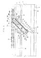
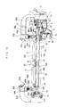
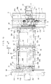
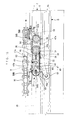
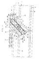
- FIG. 1 is a plan view showing a first embodiment of the present invention wherein a sorting conveyor in a sorting system is inclined through a small angle;
- FIG. 2 is a side view of the sorting system;
- FIG. 3 is a plan view of the sorting system;
- FIG. 4 is a side view showing that the sorting conveyor in the sorting system extends in a horizontal direction;
- FIG. 5 is a vertically sectional side view showing that the sorting conveyor in the sorting system is inclined through a large angle;
- FIG. 6 is a vertically sectional side view showing that the sorting conveyor in the sorting system is inclined through a small angle;
- FIG. 7 is a vertically sectional front view showing that the sorting conveyor in the sorting system extends in the horizontal direction;
- FIG. 8 is a vertically sectional front view showing that the sorting conveyor in the sorting system is inclined through a small angle;
- FIG. 9 is a vertically sectional front view of an essential part of the sorting system, showing that the sorting conveyor is inclined through a small angle;
- FIG. 10 is a schematic side view illustrating how the sorting conveyor in the sorting system is inclined;
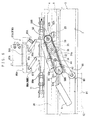
- FIG. 11 is a plan view showing a second embodiment of the present invention wherein the sorting conveyor in the sorting system is inclined through a small angle;
- FIG. 12 is a vertically sectional front view showing that the sorting conveyor in the sorting system is inclined through a small angle;
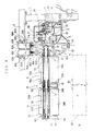
- FIG. 13 is a plan view showing a third embodiment of the present invention wherein the sorting conveyor in the sorting system is inclined through a small angle;
- FIG. 14 is a vertically sectional front view showing that the sorting conveyor in the sorting system is inclined through a small angle;
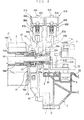
- FIG. 15 is a plan view showing a fourth embodiment of the present invention wherein the sorting conveyor in the sorting system is inclined through a small angle;
- FIG. 16 is a side view showing that the sorting conveyor in the sorting system extends in the horizontal direction;
- FIG. 17 is a vertically sectional side view showing that the sorting conveyor in the sorting system is inclined through a large angle;
- FIG. 18 is a vertically sectional side view showing that the sorting conveyor in the sorting system is inclined through a small angle;
- FIG. 19 is a vertically sectional front view showing that the sorting conveyor in the sorting system extends in the horizontal direction;
- FIG. 20 is a side view showing the sorting conveyor in the sorting system wherein endless turning bodies are extended;
- FIG. 21 is a partially cutaway plan view of the sorting conveyor in the sorting system wherein the endless turning bodies are extended;
- FIG. 22 is a side view showing the sorting conveyor in the sorting system wherein the endless turning bodies are loosened; and
- FIG. 23 is a partially cutaway plan view of the sorting conveyor in the sorting system wherein the endless turning bodies are loosened.
-
- A first embodiment of the present invention will be described below with reference to FIGS. 1 to 10.
- In FIGS. 2 and 3, a
machine frame 1 that can be arbitrarily installed on a floor is provided with a roller chain (an example of an endless turning body) 11 so that the roller chain can be arbitrarily turned. That is, themachine frame 1 is elongate and is provided withvertical shafts apparatuses vertical shafts vertical shafts sprocket wheels roller chain 11 is wound. - The
sprocket wheel 14 is used for driving and is linked with a motor (an example of a driving apparatus) 21 provided in themachine frame 1. That is, a drivingsprocket 23 provided on a driving shaft 22 of themotor 21 and apassive sprocket 24 provided on thevertical shaft 13 are linked together via atransmission chain 25. Thepassive sprocket wheel 17 can be arbitrarily moved relative to thesprocket wheel 14 by a tension adjusting means (not shown) provided between themachine frame 1 and thebearing apparatus 15. - The
roller chain 11 is provided with sortingconveyors 31 at predetermined pitches to form an endless conveyingpath 30. The group of sortingconveyors 31 are attached to aframe 3 in a cantilever manner. - That is, in FIGS. 1 to 4 and 7 to 10, the
frame 3 is disposed between thesprocket wheels roller chain 11. Theframe 3 is also attached to themachine frame 1. Here, theframe 3 is shaped like a mold rail and has a receivingguide surface 4 formed at the top thereof and at an inner position so as to face downward, a right and left guide surfaces 5 formed at an intermediate position, and asupport guide surface 6 formed at an outer position so as to face upward. Furthermore, theframe 3 has a restricting guide surface (an example of a component of guide means, described later) 7 facing both upward and downward formed at an outer position of the bottom thereof. - Each of the sorting
conveyors 31 is provided with amovement member 32 located at the position of theframe 3. Themovement member 32 is connected to a bottom surface of theroller chain 11 usinglink pins 11a also as connectors. A longitudinal pair ofguide rollers 33 are provided below themovement member 32 so as to be guide while being fitted between the right and left guide surfaces 5. - The
movement member 32 has alateral support shaft 34 penetrating therethrough and being provided with a receivedroller 35 so that theroller 35 can be arbitrarily rotated idly. The receivedroller 35 is abutted against by the receivingguide surface 4 from below. Furthermore, at the side outer than themovement member 32, a supportedroller 36 is freely and rotatably provided at thesupport shaft 34, and this supportedroller 36 is contacted to thesupport guide surface 6 from above. - The
support shaft 34 is externally elongate and is provided with aconveyor frame 40 via abearing 38. Thus, theconveyor frame 40 is attached to theroller chain 11 so as to arbitrarily incline around a horizontal axis, i.e.support shaft axis 34a, which lies at right angles to the conveyingpath 30. In this case, thesupport shaft 34 is biased frontward within the sorting conveyor relative to the conveyingpath 30. Thus, theconveyor frame 40 is automatically inclined around the support shaft axis because of its own weight in such a manner that its rear portion lies below its front portion. - The
conveyor frame 40 is composed of aninner frame portion 41, anintermediate frame portion 42, and anouter frame portion 43. Theinner frame portion 41 and theouter frame portion 43 are supported on thesupport shaft 34 via abearing 38, with theintermediate frame portion 42 penetrated by thesupport shaft 34. Aconnection shaft 44 is provided behind thesupport shaft 34 so as to extend over theframe portions 41 to 43.Connection members 45 are provided at a plurality of locations between theconnection shaft 44 and thesupport shaft 34. Thecomponents 41 to 45 constitute an example of theconveyor frame 40. - The sorting
conveyor 31 is provided with a pair of front rollers (examples of front wheels) 52A and 52B and a pair of rear rollers (examples of rear wheels) 57A and 57B, both pairs extending in a transverse direction W. The sortingconveyor 31 is also provided with a pair (plurality) of endless belts (examples of endless turning bodies) 58A and 58B wound between therollers rollers endless belts path 30. - That is, the
conveyor frame 40 has afront wheel shaft 50 installed in a front portion thereof and extending in the transverse direction W. Thefront wheel shaft 50 is rotatably supported on theframe portions 41 to 43 via abearing 51. Thefront wheel shaft 50 has a rightfront roller 52B, one of the front wheels, connected to a right portion thereof via a half-moon shaft portion 53. Further, thefront wheel shaft 50 has a leftfront roller 52A connected to a left portion thereof and a cylindrical shaft (another example of a front wheel shaft) 54 externally fitted thereon and connected to the leftfront roller 52A so that thecylindrical shaft 54 is relatively rotatable via abearing 55. - Furthermore,
rear wheel shafts frame portions 41 to 43, arranged adjacent to each other in the rear of theconveyor frame 40. Therear wheel shafts rear rollers rollers Endless belts rollers rollers endless belts path 30. - The
endless belts crossbars crossbars bracket 60 extends rearward from the rear of theinner frame portion 41 of theconveyor frame 40 and has a guided roller (an example of a guided body) 61 installed at an idle end thereof and fitted on the restrictingguide surface 7. - The
front wheel shaft 50 is provided with a friction wheel (an example of a passive wheel) 62B at an end thereof located closer to theframe body 3, thefriction wheel 62B being linked with the rightfront roller 52B. Further, thecylindrical shaft 54 has a friction wheel (an example of a passive wheel) 62A integrally formed at an end located inside thefriction wheel 62B, thefriction wheel 62A being linked with the leftfront roller 52A. Thefriction wheels friction layers - The
frame portions 41 to 43 of theconveyor frame 40 each have aside guide 63 extending laterally toward theendless belts movement member 32 is provide withguide rollers 39 arranged in front of and behind the receivedroller 35. Further, themovement member 32 is provided with a detectedportion 65. Thecomponents 32 to 65 and others constitute an example of the sortingconveyor 31. - The conveying
path 30 is elliptic and endless and has a lateral pair of linear path portions formed therein. One of the linear path portions has supply means 71 arranged opposite a start end thereof to feed books (examples of sorted articles) A onto the sortingconveyors 31. This linear path portion has a group ofreceipt sections 91 arranged opposite a terminal portion thereof to receive the books A from the sortingconveyors 31. - The sorting
conveyor 31 has guide means for restricting inclination which is arranged along the conveyingpath 30 to guidedroller 61 in the sortingconveyor 31. Accordingly, the sortingconveyor 31 receives the books A from the supply means 71 while theendless belts crossbars receipt sections 91. - The guide means is partially composed of the restricting
guide surface 7 described previously. The guide means is set so that while theguide roller 61 is being guided along the restrictingguide surface 7, theendless belts conveyor 31 are inclined through a smaller angle (about 20°). The forming member of the restrictingguide surface 7 of theframe body 3 is removed from a portion extending from a location beyond the supply means 71 to a location slightly beyond thereceipt sections 91, with the guide (an example of a component of the guide means ) 8 provided in this removed portion. - The
guide 8 is composed of a startend lifting section 8a that lifts the guidedroller 61 from the restrictingguide surface 7, a higherhorizontal portion 8b connected to the startend lifting section 8a and located above the restrictingguide surface 7, a loweringsection 8c connected to the upperhorizontal portion 8b, a lowerhorizontal portion 8d connected to the loweringsection 8c and located below the restrictingguide surface 7, and aterminal lifting section 8e connected to the lowerhorizontal portion 8d to lead the guidedroller 61 to the restrictingguide surface 7. - In this case, while the
guide roller 61 is being guided along the higherhorizontal portion 8b, theendless belts conveyor 31 lie in the horizontal direction. On the other hand, while theguide roller 61 is being guided along the lowerhorizontal portion 8d, theendless belts conveyor 31 are inclined through a larger angle (about 45°). Theguide 8 is mounted on theframe body 3. - The supply means 71 is composed of a plurality of belt conveyors, i.e. a receiving
conveyor 72, anintermediate conveyor 73, aloading conveyor 74, and others. The start end of the receivingconveyor 72 forms a receivingsection 75 that artificially or mechanically delivers the books A to the receivingconveyor 72. Further, theloading conveyor 74 is disposed so as to be inclined with its terminal located below its start end. An external portion of the terminal forms aloading section 76 that loads the books onto the sortingconveyors 31. Abar code reader 77 is provided in the supply means 71. - The group of
receipt sections 91 are disposed below the conveyingpath 30. Each of thereceipt sections 91 is provided with a pair of turning force applying means 81A and 81B for turning theendless belts target sorting conveyor 31. The turning force applying means 81A and 81B are constructed so as to arbitrarily act individually on thefront wheel shaft 50 and thecylindrical shaft 54, located closer to the frame body 3 (closer to one side of the sorting conveyors). - In this case, the turning force applying means 81A and 81B are constructed so as to arbitrarily move toward or away from the
friction wheels friction wheels path 30 for the sortingconveyors 31. - That is, in FIGS. 1, 6, 8, and 9, the
machine frame 1 is provided with a holdingframe 2 extending above and across the conveyingpath 30. The turning force applying means 81A and 81B have guidedcylinder apparatuses frame 2 viabrackets cylinder apparatuses piston rods higher elevators Lower elevators higher elevators link mechanisms link mechanisms stopper sections higher elevators - Friction rails 89A and 89B are provided below the
lower elevators friction wheels friction layers link mechanisms higher elevator link mechanisms friction wheels coil springs - Accordingly, the
friction wheels lower elevators friction wheels conveyors 31 to drive and rotate therollers endless belts - In this case, the friction acting length of the friction rails 89A and 89B is set so that the pair of
crossbars rollers rollers crossbars rollers rollers components - In FIGS. 2, 3, and 8, the group of
receipt sections 91 are constructed by providinghousing boxes 92 with their top open below the conveyingpath 30. Each of thehousing boxes 92 has a right and lefthousing sections 93 formed therein. Further, detection means 95 is provided correspondingly to eachreceipt section 91 in order to detect the detectedportion 65 of the sortingconveyor 31. - The operation of the first embodiment, described above, will be described below.
- Before the sorting system is used to sort the books A, each
receipt section 91 hasempty housing boxes 92 set therein. Thehousing boxes 92 are provided for each shop, and a signal for each shop is input to the control section. - Further, the group of sorting
conveyors 31 are moved on the conveyingpath 30 like an endless train. The sorting conveyors are moved via themovement member 32, connected to theroller chain 11 and supported and guided on theframe body 3, by causing themotor 21 to drive and rotate the driving shaft 22 and transmitting this rotating force to thesprocket wheel 14 via the drivingsprocket 23, thetransmission chain 25, thepassive sprocket 24, and thevertical shaft 13 to turn theroller chain 11. - In this case, the lateral deflection or deviation of the
movement member 32 can be restricted by using the right and leftguide surfaces 5 to guide the longitudinal pair ofguide rollers 33. Further, themovement member 32 can be prevented from floating by receiving and guiding the guidedroller 35 and theguide rollers 39 on the receivingguide surface 4. Furthermore, themovement member 32 can be prevented from lowering by supporting and guiding supportedrollers 36 on thesupport guide surface 6. - Consequently, the group of sorting
conveyors 31 are attached to theroller chain 11 in a cantilever manner, i.e. the driving and support arrangements are disposed only at one side of the sorting conveyors, thereby simplifying the system and enabling easy maintenance. Nevertheless, the group of sortingconveyors 31 can always be stably moved. The group of sortingconveyors 31 being moved normally have each group of thecrossbars rollers - Under these conditions, the books A to be sorted are placed on the receiving
conveyor 72 of the supply means 71 via the receivingsection 75. During transportation from the receivingconveyor 72 to theintermediate conveyor 73, thebar code reader 77 reads the bar codes on the books A and inputs the read signal to the control signal. The books A from theloading conveyor 74 are then loaded into the sortingconveyor 31, located below theloading section 76. - In this case, the guided
roller 61 of the sortingconveyor 31 is guided along the higherhorizontal portion 8b to allow theendless belts endless belts endless belts housing sections 93 each book A is housed. - As described above, the sorting
conveyor 31 supporting the books A on theendless belts loading section 76 toward the group ofreceipt sections 91. During this movement, as shown in FIG. 10B, the guidedroller 61 is guided from the higherhorizontal portion 8b to the loweringsection 8c to incline (turn) the sortingconveyor 31, i.e. theendless belts support shaft axis 34a so that the supply side at the rear end thereof lies below the other side. - Then, the guided
roller 61 is guided from the loweringsection 8c to the lowerhorizontal portion 8d to allow theendless belts endless belts crossbars endless belts - After the supported positions of the books A thus have been corrected, the guided
roller 61 is guided from the lowerhorizontal portion 8d to theterminal elevating section 8e to incline (turn) theendless belts support shaft axis 34a so as to raise the supply side at the rear end thereof, as shown in FIG. 10C. Then, the guidedroller 61 is guided from theterminal elevating section 8e to the restrictingguide surface 7 to reduce the inclination of theendless belts - In this manner, the group of sorting
conveyors 31 with theendless belts receipt sections 91. Then, before the sortingconveyor 31 reaches thetarget receipt section 91, the detection means 95 detects the detectedportion 65 of the sortingconveyor 31. In response to an instruction from the control section, to which the detection signal has been input, the turning force applying means 81A and 81B corresponding to thisreceipt section 91 are operated. At this time, one or both of the turning force applying means 81A and 81B may be operated. - That is, the
cylinder apparatuses higher elevators lower elevators link mechanisms friction wheels conveyor 31 slip under the friction rails 89A and 89B, respectively, and roll on the friction layers 89a and 89b of the friction rails 89A and 89B, respectively. Thus, large frictional resistance is generated to reliably rotate thefriction wheels - At this time, the
front roller 52A can be forcibly rotated via thecylindrical shaft 54, to which thefriction wheel 62A is attached. The forced rotation of thefront roller 52A enables theendless belt 58A to be turned along the conveyingpath 30 while rotating thefront roller 52A idly so that the higher portion of theendless belt 58A is inclined and lowered. Consequently, as shown in FIGS. 6 and 10D, the book A supported on theendless belt 58A is fed and loaded into thetarget housing box 92. - Further, the other
front roller 52B can be forcibly rotated via thefront wheel shaft 50, to which thefriction wheel 62B is attached. The forced rotation of thefront roller 52B enables theendless belt 58B to be turned along the conveyingpath 30 while rotating thefront roller 52B idly so that the higher portion of theendless belt 58B is inclined and lowered. Consequently, as shown in FIGS. 6 and 10D, the book A supported on theendless belt 58B is fed and loaded into thetarget housing box 92. - In this case, one or both of the turning force applying means 81A and 81B are operated in response to an instruction from the control section, as described previously. Accordingly, when both turning force applying means 81A and 81B are operated, both
endless belts path 30. Consequently, the books A supported on theendless belts corresponding housing sections 93 of thetarget housing box 92. - On the other hand, when one of the turning force applying means 81A and 81B is operated, the corresponding one of the
endless belts path 30. Consequently, only the book A supported on theendless belt corresponding housing section 93 of thetarget housing box 92. - In this manner, when the books A are loaded into the
corresponding housing sections 93 of thetarget housing box 92, the books A on theendless belt endless belts corresponding housing sections 93 of thehousing box 92. - Further, as described previously, the
endless belts receipt sections 91 can be disposed below the group of sortingconveyors 31, i.e. the conveyingpath 30, thereby saving space and enabling books to be sorted and loaded directly into thehousing sections 93 of thehousing box 92. Therefore, compared to a form provided with a separate slide (slide slope), required planar space is reduced to enable easy layout. - The
friction wheels coil springs friction wheels - Thus, the
endless belts crossbars rollers rollers crossbars rollers rollers - As described previously, once the books A have been completely fed by turning the
endless belts same housing box 92, the friction rails 89A and 89B may stand by at the operative positions, where they have been lowered, without being elevated to the inoperative positions. - Since the
housing box 92 has a vertically extending outside shape, the books A can be easily housed in thehousing box 92 and thehousing box 92 can be easily moved into and out of thereceipt section 91. - Now, a second embodiment of the present invention will be described with reference to FIGS. 11 and 12.
- In the second embodiment, the group of sorting
conveyors 31 are attached to the frame body in a cantilever manner. The turning force applying means 81A and 81B are arranged at the right and left sides of the sortingconveyor 31, respectively, so as to arbitrarily act on the friction wheels (passive wheels) 62A and 62B, respectively, located opposite each other. - That is, a
frame body 3X is disposed opposite theframe body 3 via the conveyingpath 30 and has a receivingguide surface 4X formed at an inner position thereof so as to face upward. A receivedroller 35X is provided at the outer end of thelateral support shaft 34 so as to arbitrarily rotate idly. Further, the receivingguide surface 4X abuts against the receivedroller 35X from above. Thus, the group of sortingconveyors 31 are attached to theframe bodies - Further, the outer end of the
front wheel shaft 50 is projected. This projecting portion is provided with thefriction wheel 62B, opposite which the turning force applying means 81B is arranged. Accordingly, the turning force applying means 81A and 81B are disposed at the respective lateral ends of the sorting conveyor so as to arbitrarily act on thefriction wheels - In the second embodiment, the
roller chain 11 is turned to enable the group of sortingconveyors 31 connected to theroller chain 11 to be moved on the conveyingpath 30 like an endless train, while being supported and guided along theframe bodies conveyor 31 can be prevented from floating by receiving and guiding the receivedroller 35 and theguide roller 39 on the receivingguide surface 4. The outer end of the sortingconveyor 31 can be prevented from lowering by supporting and guiding the receivedroller 35X on the receivingguide roller 4X. - Therefore, the group of sorting
conveyors 31 are connected to theroller chain 11 at one side thereof, i.e. the driving and support arrangements are disposed only at one side of the sorting conveyors, thereby simplifying the system and enabling easy maintenance. Nevertheless, the group of sortingconveyors 31 can be more stably moved because they are attached to theframe bodies - Before the sorting
conveyor 31 reaches thetarget receipt section 91, the turning force applying means 81A and 81B corresponding to thisreceipt section 91, i.e. one or both of the turning force applying means 81A and 81B are operated to force out the books A supported on theendless belts target housing box 92. In this case, since the turning force applying means 81A and 81B are disposed at the right and left sides of the sorting conveyor, respectively, it is easy to check the operation of each of the turning force applying means 81A and 81B or to carry out maintenance inspections. - Now, a third embodiment of the present invention will be described with reference to FIGS. 13 and 14.
- In the third embodiment, the group of sorting
conveyors 31 are attached to the frame body in a cantilever manner. The sortingconveyor 31 has guided bodies arranged at the right and left sides thereof, respectively, and a pair of guide means along which the respective guided bodies are guided. - That is, a
frame body 3Y is disposed opposite theframe body 3 via the conveyingpath 30 and has a receivingguide surface 4Y formed thereon so as to face upward, and a restricting guide surface (an example of a component of the guide means) 7Y formed thereon so as to face both upward and downward. A receivedroller 35Y is provided at the outer end of thelateral support shaft 34 so as to arbitrarily rotate idly. Further, the receivingguide surface 4Y abuts against the receivedroller 35Y from above. Thus, the group of sortingconveyors 31 are attached to theframe bodies - Further, the outer end of the
front wheel shaft 50 is projected. This projecting portion is provided with thefriction wheel 62B, opposite which the turning force applying means 81B is arranged. Accordingly, the turning force applying means 81A and 81B are disposed at the respective lateral ends of the sorting conveyor so as to arbitrarily act on thefriction wheels - Furthermore, a
bracket 60Y extends rearward from the rear of theouter frame portion 43 of theconveyor frame 40. Thebracket 60Y has a guided roller (an example of a guided body) 61Y installed at an idle end thereof and fitted on the restrictingguide surface 7Y. Thereby, the guided rollers (guided bodies) 61, 61Y are distributed left and right and provided at the side of the sortingconveyors 31, and there are also provided a pair of restricting guide surfaces (constituent material of guide means) 7, 7Y by which these guidedrollers - In the third embodiment, the
roller chain 11 is turned to enable the group of sortingconveyors 31 connected to theroller chain 11 to be moved on the conveyingpath 30 like an endless train, while being supported and guided along theframe bodies conveyor 31 can be prevented from floating by receiving and guiding the receivedroller 35 and theguide roller 39 on the receivingguide surface 4. The outer end of the sortingconveyor 31 can be prevented from lowering by supporting and guiding the receivedroller 35Y on the receivingguide roller 4Y. - Therefore, the group of sorting
conveyors 31 are connected to theroller chain 11 at one side thereof, i.e. the driving and support arrangements are disposed only at one side of the sorting conveyors, thereby simplifying the system and enabling easy maintenance. Nevertheless, the group of sortingconveyors 31 can be more stably moved because they are attached to theframe bodies - When the sorting
conveyor 31 having the books A on theendless belts loading section 76 to the group ofreceipt sections 91, theguide rollers horizontal portion 8b to the loweringsection 8c. Accordingly, the sortingconveyor 31, i.e. theendless belts support shaft axis 34a so that the supply side at the rear end thereof lies below the other side. - Then, the guided
rollers section 8c to the lowerhorizontal portion 8d to allow theendless belts rollers horizontal portion 8d to theterminal elevating section 8e to incline (turn) theendless belts support shaft axis 34a so as to raise the supply side at the rear end thereof. Then, the guidedrollers terminal elevating section 8e to the restrictingguide surfaces endless belts - In this manner, the guided
rollers guide 8 and the restrictingguide surfaces conveyors 31 can always be smoothly and stably inclined and swayed laterally synchronously without being subjected to twist or the like. - As described above, the group of sorting
conveyors 31 with theendless belts receipt sections 91. Then, before the sortingconveyor 31 reaches thetarget receipt section 91, the books A supported on theendless belts target housing box 92 by operating the turning force applying means 81A, 81B corresponding to thereceipt section 91, i.e. one or both of the turning force applying means 81A and 81B. In this case, since the turning force applying means 81A and 81B are arranged at the right and left sides of the sorting conveyor, respectively, it is easy to check the operation of each of the turning force applying means 81A and 81B or carry out maintenance inspections. - In the first to third embodiments, the lateral pair of
endless belts - Now, a fourth embodiment of the present invention will be described with reference to FIGS. 15 to 23.
- In the fourth embodiment, the
conveyor frame 40 is composed of theinner frame body 41, theintermediate frame body 42, and theouter frame body 43. Theframe bodies 41 to 43 are composed offront frame portions intermediate frame portions rear frame portions - The
front frame portions outer frame bodies front frame portions support shaft 34 via thebearing 38, and thefront frame portion 42a of theintermediate frame body 42 has thesupport shaft 34 inserted therethrough. Further, the rear ends of thefront frame portions intermediate portions connectors 46 are used to connect these portions together, abelt receiver 45Z facing upward is simultaneously connected. Further, aconnection shaft 44 is provided so as to extend over theintermediate frame portions - The
rear frame portions horizontal pin 47 extending in the lateral direction W, in the vertical direction relative to the rear end of the corresponding one of theintermediate frame portions rear frame portions intermediate frame portions intermediate frame portions rear frame portions intermediate frame portions components 41 to 48 constitute an example of theconveyor frame 40. - The
front frame portions 41a to 43a of theconveyor frame 40 each have thefront wheel shaft 50 installed in front thereof and extending in the transverse direction W. Thefront wheel shaft 50 is rotatably supported on thefront frame portions 41a to 43a via thebearing 51 and the like. Furthermore, therear frame portions conveyor frame 40, have therear wheel shafts position adjusting member 49 and extending in the transverse direction W. Therear wheel shafts rear rollers rollers frame bodies 41 to 43 of theconveyor frame 40, the side guides 63 are removably provided at the right and left sides of each of theendless belts 58A and 58b via the connectors (bolts and nuts) 64. - In the fourth embodiment, while the books A are being sorted as described above and shown in FIGS. 15 to 19, the
conveyor frame 40 assumes the horizontal position where therear frame portions intermediate frame portions fixtures 48. In this position, theendless belts rear rollers front rollers friction wheels front rollers endless belts - As the sorting system is used over time, the
endless belts connectors 64 are removed to separate the side guides 63 from the sorting conveyor. Further, theposition adjusting members 49 are removed (or loosened) as required. Then, thefixtures 48 are removed to sway therear frame portions horizontal pin 47 relative to theintermediate frame portions rear frame portions - In this position, the
endless belts rear rollers front rollers endless belts frame body 3. Then, newendless belts front rollers rear rollers endless belts - Then, the
rear frame portions horizontal pin 47 relative to theintermediate frame portions rear frame portions intermediate frame portions fixtures 48. Subsequently, the side guides 63 are installed, and theposition adjusting members 49 are operated for adjustments. - Accordingly, the
endless belts endless belts - In the fourth embodiment, the
rear rollers endless belts front rollers endless belts front rollers rear rollers endless belts - In the fourth embodiment, the
rear frame portions horizontal pin 47 to enable therear rollers endless belts rear frame portions intermediate frame portions - In the fourth embodiment, the pair of
endless belts - In each of the above described embodiments, the
endless belts endless belts crossbars front rollers rear rollers - In each of the above described embodiments, the books A are sorted. However, other articles or loads may be sorted. The shape of the
receipt section 91 may vary depending the type of sorted articles. - In each of the above described embodiments, as the endless turning bodies the
endless belts - In each of the above described embodiments, the front rollers (front wheels) 52A and 52B are provided with the friction wheels (passive wheels) 62A and 62B. However, the rear rollers (rear wheels) 57A and 57B may be provided with the
friction wheels - In each of the above described embodiments, in the turning force applying means 81A and 81B, the friction wheels (passive wheels) 62A and 62B can be abutted against or separated from the friction rails 89A and 89B, respectively. However, racks may be meshed with pinions (passive wheels), or rails may be abutted against or separated from rollers (passive wheels) with the friction layers 62a, 62b, 89a, and 89b not employed.
- In each of the above described embodiments, the
endless belts conveyor 31 are inclined around thesupport shaft axis 34a so that the supply side at the rear end thereof lies below the other side. However, theendless belts support shaft axis 34a so that the supply side at the front end thereof lies below the other side. In this case, the turning force applying means 81A and 81B are constructed so that the friction rails 89A and 89B can be abutted against or separated from thefriction wheels - In each of the above described embodiments, the group of
receipt sections 91 are disposed below the conveyingpath 30. However, the books A fed by theendless belts housing box 92.
Claims (13)
- A sorting system comprising:wherein each of said sorting conveyors includes a group of front wheels and a group of rear wheels each extending in a transverse direction, and a plurality of endless turning bodies wound around wheels opposed to each other in a front-and-rear direction, each endless turning body being capable of individually turning along the conveying path; andan endless driving body provided with a plurality of sorting conveyors to form an endless conveying path; anda group of receipt sections arranged to oppose the conveying path and receiving sorted articles from the sorting conveyors,
wherein each of the receipt sections is provided with turning force applying units for turning target endless turning bodies of a target sorting conveyor. - The sorting system according to claim 1, wherein the sorting conveyor includes passive wheels linked with one of the group of front wheels and the group of rear wheels, and the turning force applying units are movable toward or away from target passive wheels to be engageable therewith, so that the passive wheels are rotated by movement force exerted along the conveying path of the sorting conveyor.
- The sorting system according to claim 1, wherein the sorting conveyor has a front wheel shaft extending in the transverse direction and having one of the lateral pair of front wheels connected thereto, with the other front wheel being rotatably fitted over the sorting conveyor via a cylindrical shaft, and the turning force applying units are arranged to act individually on the front wheel shaft and the cylindrical shaft on one of the lateral sides of the sorting conveyor.
- The sorting system according to claim 1, wherein the sorting conveyor includes a lateral pair of front wheel shafts, each shaft being connected to one of the wheels and provided with a passive wheel, and the turning force applying units are arranged at opposite lateral sides of the sorting conveyor, respectively, to individually act on the opposite passive wheels.
- The sorting system according to claim 1, wherein the sorting conveyor has crossbars formed on the endless turning bodies and is mounted on the endless driving body side to be freely inclined around a horizontal axis lying at right angles to the conveying path, the sorting conveyor including guided bodies to receive sorted articles while the endless turning bodies lie in a horizontal direction and to reach the group of receipt sections while the endless turning bodies are inclined such that a supply side thereof on which the crossbars are located lies lower than the other side thereof, the sorting conveyor further including inclination-restricting guide members extended along the conveying path and guiding the guided bodies.
- The sorting system according to claim 1, wherein the group of sorting conveyors are attached to a frame body in a cantilever manner.
- The sorting system according to claim 1, wherein the group of sorting conveyors are attached to a frame body in a center impeller manner.
- The sorting system according to claim 5, wherein the group of sorting conveyors are attached to the frame body in a center impeller manner, and the sorting conveyors are provided with guided bodies allocated on opposite lateral sides thereof and a pair of guide members along which the guided bodies are guided.
- A sorting system comprising:wherein each sorting conveyor comprises a front wheel, a rear wheel, and an endless turning bodies wound between both wheels and capable of freely turning in a direction of the conveying path, said sorting conveyor being supported and guided on a frame body in a cantilever manner, at least one of said wheels being movable between a position where the endless turning bodies are stretched and a position where the endless turning bodies are loosened.an endless driving body provided with a plurality of sorting conveyors to form an endless conveying path; anda group of receipt sections arranged to oppose the conveying path and receiving sorted articles from the sorting conveyors,
- The sorting system according to claim 9, wherein at least one of the wheels is rotatably supported by a swaying section provided in a conveyor frame, said swaying section being fixable to the conveyor frame when the wheel is at the position where the endless turning bodies are stretched.
- The sorting system according to claim 9, wherein the front wheel is held in position and the rear wheel is held to be movable with respect to the conveyor frame, and a group of receipt sections for receiving sorted articles from the sorting conveyors are provided to oppose the conveying path, each of said receipt sections being provided with turning force applying units for turning the endless turning bodies of a target sorting conveyor, the turning force applying units being movable toward or away from passive wheels provided to the front wheel side, to be engageable therewith, so that the passive wheels are rotated by movement force exerted along the conveying path of the sorting conveyor.
- The sorting system according to claim 9, wherein each sorting conveyor has a plurality of front wheels and rear wheels each extending in a transverse direction, and a plurality of endless turning bodies wound between wheels opposed to each other in a longitudinal direction and being individually turnable in the direction of the conveying path, and each receipt section is provided with turning force applying units for turning target endless turning bodies of a target sorting conveyor.
- The sorting system according to claim 9, wherein the sorting conveyor has crossbars formed on the endless turning bodies and is mounted on the endless driving body side to be freely inclined around a horizontal axis lying at right angles to the conveying path, the sorting conveyor including guided bodies to receive sorted articles while the endless turning bodies lie in a horizontal direction and to reach the group of receipt sections while the endless turning bodies are inclined such that a supply side thereof on which the crossbars are located lies lower than the other side thereof, the sorting conveyor further including inclination-restricting guide members extended along the conveying path and guiding the guided bodies.
Applications Claiming Priority (4)
| Application Number | Priority Date | Filing Date | Title |
|---|---|---|---|
| JP2001313351A JP3772719B2 (en) | 2001-10-11 | 2001-10-11 | Sorting equipment |
| JP2001313351 | 2001-10-11 | ||
| JP2001356792 | 2001-11-22 | ||
| JP2001356792A JP3815306B2 (en) | 2001-11-22 | 2001-11-22 | Sorting equipment |
Publications (2)
| Publication Number | Publication Date |
|---|---|
| EP1302416A1 true EP1302416A1 (en) | 2003-04-16 |
| EP1302416B1 EP1302416B1 (en) | 2005-12-07 |
Family
ID=26623841
Family Applications (1)
| Application Number | Title | Priority Date | Filing Date |
|---|---|---|---|
| EP02079048A Expired - Lifetime EP1302416B1 (en) | 2001-10-11 | 2002-10-02 | Sorting system |
Country Status (5)
| Country | Link |
|---|---|
| US (1) | US6732849B2 (en) |
| EP (1) | EP1302416B1 (en) |
| KR (1) | KR100534163B1 (en) |
| CN (1) | CN1247425C (en) |
| DE (1) | DE60207804T2 (en) |
Families Citing this family (11)
| Publication number | Priority date | Publication date | Assignee | Title |
|---|---|---|---|---|
| US20030221935A1 (en) * | 1998-12-01 | 2003-12-04 | Crisplant A/S | Conveyor/sorter system, a loading conveyor and a control system for such conveyors |
| US20060278501A1 (en) * | 2004-09-02 | 2006-12-14 | Sweazy Eric W | Conveyor/sorter apparatus and method |
| JP4065926B2 (en) * | 2004-10-21 | 2008-03-26 | 株式会社ダイフク | Carriage transfer device |
| US9268054B2 (en) * | 2011-07-07 | 2016-02-23 | Robert Osann, Jr. | Synchronized robotic baggage portal for secure access |
| JP5682491B2 (en) * | 2011-07-14 | 2015-03-11 | 住友電装株式会社 | Conveyor device for assembly work |
| ES2686698T3 (en) | 2012-07-11 | 2018-10-19 | Dematic Corp. | Cross-tape sorting system and article classification method |
| JP2016210614A (en) * | 2015-05-11 | 2016-12-15 | 株式会社東芝 | Article sorting equipment |
| CN110636981B (en) | 2017-03-08 | 2021-10-26 | 雷勃美国公司 | Package sorting and conveying module and system and method thereof |
| US10532894B2 (en) | 2017-03-10 | 2020-01-14 | Regal Beloit America, Inc. | Modular transfer units, systems, and methods |
| US10608469B2 (en) * | 2017-09-28 | 2020-03-31 | Rockwell Automation Technologies, Inc. | Method and apparatus for power transfer to an independent moving cart during travel along a track |
| AU2018372168B2 (en) | 2017-11-22 | 2024-07-18 | Regal Beloit America, Inc. | Modular sortation units, systems, and methods |
Citations (4)
| Publication number | Priority date | Publication date | Assignee | Title |
|---|---|---|---|---|
| DE2007439A1 (en) * | 1969-02-18 | 1970-09-10 | ||
| EP0611713A2 (en) * | 1993-02-19 | 1994-08-24 | FINMECCANICA S.p.A. | Handling-switching apparatus with conveyor tables apt to be inclined, with unloading actuating devices controlled by said conveyor tables |
| JPH08301438A (en) | 1995-04-28 | 1996-11-19 | Daifuku Co Ltd | Sorter equipment |
| EP0752280A2 (en) * | 1995-07-04 | 1997-01-08 | FINMECCANICA S.p.A. | Sorting machine with always tilted transportation planes |
Family Cites Families (5)
| Publication number | Priority date | Publication date | Assignee | Title |
|---|---|---|---|---|
| IT211603Z2 (en) | 1985-12-20 | 1989-04-07 | Canziani Francesco | TRANSPORT AND UNLOADING UNIT FOR SORTING OBJECTS. |
| NL8600433A (en) * | 1986-02-20 | 1987-09-16 | Johannes Gerhardus Christianus | TRANSPORT DEVICE. |
| JPS6490713A (en) | 1987-10-01 | 1989-04-07 | Asahi Chemical Ind | Molding method for thermosetting resin oriented molded product |
| JPH07115362B2 (en) | 1987-10-01 | 1995-12-13 | 株式会社野田ワックス | Manufacturing method of large wax lumps |
| IT1263944B (en) | 1993-02-19 | 1996-09-05 | SORTING MACHINE WITH DEVICES SUITABLE TO KEEP THE OBJECTS TRANSPORT PLANS HORIZONTALLY |
-
2002
- 2002-09-27 US US10/256,392 patent/US6732849B2/en not_active Expired - Lifetime
- 2002-10-02 EP EP02079048A patent/EP1302416B1/en not_active Expired - Lifetime
- 2002-10-02 DE DE60207804T patent/DE60207804T2/en not_active Expired - Lifetime
- 2002-10-10 KR KR10-2002-0061704A patent/KR100534163B1/en not_active Expired - Fee Related
- 2002-10-10 CN CNB021575029A patent/CN1247425C/en not_active Expired - Fee Related
Patent Citations (4)
| Publication number | Priority date | Publication date | Assignee | Title |
|---|---|---|---|---|
| DE2007439A1 (en) * | 1969-02-18 | 1970-09-10 | ||
| EP0611713A2 (en) * | 1993-02-19 | 1994-08-24 | FINMECCANICA S.p.A. | Handling-switching apparatus with conveyor tables apt to be inclined, with unloading actuating devices controlled by said conveyor tables |
| JPH08301438A (en) | 1995-04-28 | 1996-11-19 | Daifuku Co Ltd | Sorter equipment |
| EP0752280A2 (en) * | 1995-07-04 | 1997-01-08 | FINMECCANICA S.p.A. | Sorting machine with always tilted transportation planes |
Also Published As
| Publication number | Publication date |
|---|---|
| US20030079958A1 (en) | 2003-05-01 |
| CN1247425C (en) | 2006-03-29 |
| KR100534163B1 (en) | 2005-12-06 |
| DE60207804D1 (en) | 2006-01-12 |
| KR20030030946A (en) | 2003-04-18 |
| CN1417095A (en) | 2003-05-14 |
| US6732849B2 (en) | 2004-05-11 |
| DE60207804T2 (en) | 2006-09-14 |
| EP1302416B1 (en) | 2005-12-07 |
Similar Documents
| Publication | Publication Date | Title |
|---|---|---|
| US9809388B2 (en) | Cross belt slat sorter | |
| EP1302416B1 (en) | Sorting system | |
| CN101918292A (en) | Apparatus and method for actuating conveyor belt rollers | |
| JP4828801B2 (en) | Method of changing the direction of conveyed items on a conveyor | |
| KR102472545B1 (en) | Conveyor system for battery activation process | |
| JP2014152026A (en) | Turnaround device for material to be conveyed | |
| JP5024631B2 (en) | Sorting equipment | |
| AU705758B2 (en) | High capacity stacker/separating device | |
| JP4511205B2 (en) | Container supply device | |
| EP2001770B1 (en) | Conveyor for conveying and buffering products | |
| JP2001199514A (en) | Tray type article conveyer | |
| JP4720631B2 (en) | Sorting equipment | |
| JP3815306B2 (en) | Sorting equipment | |
| JP4795321B2 (en) | Loading device | |
| JP3772719B2 (en) | Sorting equipment | |
| JP5034811B2 (en) | Sorting equipment | |
| JP4857990B2 (en) | Sorting equipment | |
| JP3797112B2 (en) | Sorting equipment | |
| JP4281455B2 (en) | Transport equipment | |
| JP3760779B2 (en) | Sorting equipment | |
| JP4289200B2 (en) | Transport equipment | |
| KR101482277B1 (en) | An apparatus for supporting a belt included in a belt conveyor | |
| JP3797111B2 (en) | Sorting equipment | |
| KR100815800B1 (en) | Meandering device of belt conveyor | |
| JP3815230B2 (en) | Conveyor equipment and sorting equipment using conveyor equipment |
Legal Events
| Date | Code | Title | Description |
|---|---|---|---|
| PUAI | Public reference made under article 153(3) epc to a published international application that has entered the european phase |
Free format text: ORIGINAL CODE: 0009012 |
|
| AK | Designated contracting states |
Designated state(s): AT BE BG CH CY CZ DE DK EE ES FI FR GB GR IE IT LI LU MC NL PT SE SK TR |
|
| AX | Request for extension of the european patent |
Extension state: AL LT LV MK RO SI |
|
| 17P | Request for examination filed |
Effective date: 20030704 |
|
| AKX | Designation fees paid |
Designated state(s): DE FR GB IT NL |
|
| 17Q | First examination report despatched |
Effective date: 20041109 |
|
| GRAP | Despatch of communication of intention to grant a patent |
Free format text: ORIGINAL CODE: EPIDOSNIGR1 |
|
| GRAS | Grant fee paid |
Free format text: ORIGINAL CODE: EPIDOSNIGR3 |
|
| GRAA | (expected) grant |
Free format text: ORIGINAL CODE: 0009210 |
|
| AK | Designated contracting states |
Kind code of ref document: B1 Designated state(s): DE FR GB IT NL |
|
| PG25 | Lapsed in a contracting state [announced via postgrant information from national office to epo] |
Ref country code: IT Free format text: LAPSE BECAUSE OF FAILURE TO SUBMIT A TRANSLATION OF THE DESCRIPTION OR TO PAY THE FEE WITHIN THE PRESCRIBED TIME-LIMIT;WARNING: LAPSES OF ITALIAN PATENTS WITH EFFECTIVE DATE BEFORE 2007 MAY HAVE OCCURRED AT ANY TIME BEFORE 2007. THE CORRECT EFFECTIVE DATE MAY BE DIFFERENT FROM THE ONE RECORDED. Effective date: 20051207 |
|
| REG | Reference to a national code |
Ref country code: GB Ref legal event code: FG4D |
|
| REF | Corresponds to: |
Ref document number: 60207804 Country of ref document: DE Date of ref document: 20060112 Kind code of ref document: P |
|
| ET | Fr: translation filed | ||
| PLBE | No opposition filed within time limit |
Free format text: ORIGINAL CODE: 0009261 |
|
| STAA | Information on the status of an ep patent application or granted ep patent |
Free format text: STATUS: NO OPPOSITION FILED WITHIN TIME LIMIT |
|
| 26N | No opposition filed |
Effective date: 20060908 |
|
| REG | Reference to a national code |
Ref country code: FR Ref legal event code: PLFP Year of fee payment: 15 |
|
| PGFP | Annual fee paid to national office [announced via postgrant information from national office to epo] |
Ref country code: GB Payment date: 20160928 Year of fee payment: 15 Ref country code: NL Payment date: 20160913 Year of fee payment: 15 |
|
| PGFP | Annual fee paid to national office [announced via postgrant information from national office to epo] |
Ref country code: FR Payment date: 20160919 Year of fee payment: 15 |
|
| PGFP | Annual fee paid to national office [announced via postgrant information from national office to epo] |
Ref country code: DE Payment date: 20160927 Year of fee payment: 15 |
|
| PGFP | Annual fee paid to national office [announced via postgrant information from national office to epo] |
Ref country code: IT Payment date: 20161024 Year of fee payment: 15 |
|
| REG | Reference to a national code |
Ref country code: DE Ref legal event code: R119 Ref document number: 60207804 Country of ref document: DE |
|
| REG | Reference to a national code |
Ref country code: NL Ref legal event code: MM Effective date: 20171101 |
|
| GBPC | Gb: european patent ceased through non-payment of renewal fee |
Effective date: 20171002 |
|
| REG | Reference to a national code |
Ref country code: FR Ref legal event code: ST Effective date: 20180629 |
|
| PG25 | Lapsed in a contracting state [announced via postgrant information from national office to epo] |
Ref country code: DE Free format text: LAPSE BECAUSE OF NON-PAYMENT OF DUE FEES Effective date: 20180501 Ref country code: NL Free format text: LAPSE BECAUSE OF NON-PAYMENT OF DUE FEES Effective date: 20171101 Ref country code: GB Free format text: LAPSE BECAUSE OF NON-PAYMENT OF DUE FEES Effective date: 20171002 |
|
| PG25 | Lapsed in a contracting state [announced via postgrant information from national office to epo] |
Ref country code: FR Free format text: LAPSE BECAUSE OF NON-PAYMENT OF DUE FEES Effective date: 20171031 |
|
| PG25 | Lapsed in a contracting state [announced via postgrant information from national office to epo] |
Ref country code: IT Free format text: LAPSE BECAUSE OF NON-PAYMENT OF DUE FEES Effective date: 20171002 |