EP1302403A2 - Tray container and blank - Google Patents
Tray container and blank Download PDFInfo
- Publication number
- EP1302403A2 EP1302403A2 EP02022779A EP02022779A EP1302403A2 EP 1302403 A2 EP1302403 A2 EP 1302403A2 EP 02022779 A EP02022779 A EP 02022779A EP 02022779 A EP02022779 A EP 02022779A EP 1302403 A2 EP1302403 A2 EP 1302403A2
- Authority
- EP
- European Patent Office
- Prior art keywords
- tray
- panel
- base
- panels
- forming
- Prior art date
- Legal status (The legal status is an assumption and is not a legal conclusion. Google has not performed a legal analysis and makes no representation as to the accuracy of the status listed.)
- Withdrawn
Links
- 239000000463 material Substances 0.000 claims abstract description 19
- 239000011087 paperboard Substances 0.000 claims abstract description 12
- 239000002131 composite material Substances 0.000 claims abstract description 5
- 230000014759 maintenance of location Effects 0.000 claims description 33
- 239000012530 fluid Substances 0.000 claims description 15
- 238000010276 construction Methods 0.000 claims description 12
- 238000000034 method Methods 0.000 claims description 10
- 239000007788 liquid Substances 0.000 claims description 9
- 230000000717 retained effect Effects 0.000 claims description 5
- 125000006850 spacer group Chemical group 0.000 claims description 5
- 239000011800 void material Substances 0.000 claims description 5
- 239000003292 glue Substances 0.000 description 4
- 238000004519 manufacturing process Methods 0.000 description 4
- 235000013372 meat Nutrition 0.000 description 4
- 235000013305 food Nutrition 0.000 description 3
- 241000251468 Actinopterygii Species 0.000 description 2
- 238000004026 adhesive bonding Methods 0.000 description 2
- 230000015572 biosynthetic process Effects 0.000 description 2
- 239000004033 plastic Substances 0.000 description 2
- 229920003023 plastic Polymers 0.000 description 2
- 239000004793 Polystyrene Substances 0.000 description 1
- 239000011358 absorbing material Substances 0.000 description 1
- 230000003466 anti-cipated effect Effects 0.000 description 1
- 239000008280 blood Substances 0.000 description 1
- 210000004369 blood Anatomy 0.000 description 1
- 210000000416 exudates and transudate Anatomy 0.000 description 1
- 238000004806 packaging method and process Methods 0.000 description 1
- 239000000123 paper Substances 0.000 description 1
- 229920002401 polyacrylamide Polymers 0.000 description 1
- 229920000642 polymer Polymers 0.000 description 1
- 229920002223 polystyrene Polymers 0.000 description 1
- XLYOFNOQVPJJNP-UHFFFAOYSA-N water Substances O XLYOFNOQVPJJNP-UHFFFAOYSA-N 0.000 description 1
Images


Classifications
-
- B—PERFORMING OPERATIONS; TRANSPORTING
- B65—CONVEYING; PACKING; STORING; HANDLING THIN OR FILAMENTARY MATERIAL
- B65D—CONTAINERS FOR STORAGE OR TRANSPORT OF ARTICLES OR MATERIALS, e.g. BAGS, BARRELS, BOTTLES, BOXES, CANS, CARTONS, CRATES, DRUMS, JARS, TANKS, HOPPERS, FORWARDING CONTAINERS; ACCESSORIES, CLOSURES, OR FITTINGS THEREFOR; PACKAGING ELEMENTS; PACKAGES
- B65D5/00—Rigid or semi-rigid containers of polygonal cross-section, e.g. boxes, cartons or trays, formed by folding or erecting one or more blanks made of paper
- B65D5/42—Details of containers or of foldable or erectable container blanks
- B65D5/44—Integral, inserted or attached portions forming internal or external fittings
- B65D5/50—Internal supporting or protecting elements for contents
- B65D5/5028—Elements formed separately from the container body
- B65D5/5035—Paper elements
- B65D5/504—Racks having upstanding ridges formed by folds, and provided with slits or recesses
-
- B—PERFORMING OPERATIONS; TRANSPORTING
- B65—CONVEYING; PACKING; STORING; HANDLING THIN OR FILAMENTARY MATERIAL
- B65D—CONTAINERS FOR STORAGE OR TRANSPORT OF ARTICLES OR MATERIALS, e.g. BAGS, BARRELS, BOTTLES, BOXES, CANS, CARTONS, CRATES, DRUMS, JARS, TANKS, HOPPERS, FORWARDING CONTAINERS; ACCESSORIES, CLOSURES, OR FITTINGS THEREFOR; PACKAGING ELEMENTS; PACKAGES
- B65D5/00—Rigid or semi-rigid containers of polygonal cross-section, e.g. boxes, cartons or trays, formed by folding or erecting one or more blanks made of paper
- B65D5/42—Details of containers or of foldable or erectable container blanks
- B65D5/44—Integral, inserted or attached portions forming internal or external fittings
- B65D5/50—Internal supporting or protecting elements for contents
- B65D5/5021—Integral elements for containers formed by folding-up portions connected to a central panel from all sides
Definitions
- the engaging tab is located at the outer portion of the inner base panel resists the load of articles held by the retention structure to hold the retention structure in a set up position.
- an outer portion of the inner end panel is retained by the inner side panel to retain the inner end panel in a set up condition while the retention structure is formed.
- the inner panels forming the base, side and end walls are provided by an insert.
- a tray for holding foodstuff or the like which tray is formed from paperboard or like foldable sheet material and can be erected from a flat collapsed condition into a position of use, the tray comprising a plurality of panels for forming a base, opposed side and end walls wherein the panels forming the tray are a composite structure comprising inner and outer panels forming the base, side and end walls and an article retention structure struck at least in part from the outer portion of the inner base panel characterized in that an outer portion of the inner end panel is retained by the inner side panel to retain the inner end panel in a set up condition while the retention structure is formed.
- the deformable portion is hingedly connected to the adjacent side panel by a fold line in an obtuse angular relationship with the fold line connecting the end panel and base panel.
- the securing means comprises a flap hingedly connected to one of the side and end panels and foldable to be superposed with the other the side and end panels to be secured therewith, which flap is severed from the deformable portion.
- the deformable portion is provided by a gusset panel.
- the inner and outer walls forming the base and the side and end walls define one or more skinned zones providing one or more voids wherein means are provided to give fluid communication between the internal surface of the base and the void so that fluid present in the tray can drain into the voids in the base and in the side and end walls.
- the fluid communication means comprises a plurality of perforations distributed along at least one edge of the inner base wall.
- the voids may include absorbing means to absorb the liquid.
- a blank for forming a tray for holding foodstuff or the like which tray is formed from paperboard or like foldable sheet material comprising a plurality of panels for forming an outer base, opposed side and end walls and an insert comprising a plurality of panel forming the inner base, side and end walls characterised in that there further comprises an article retention structure struck from an outer portion of inner base panel such that a part of the outer portion along the inner side panel remain flat with the outer base panel in a set up condition and wherein an engaging tab is formed along the part of the end portion to engage the end slot in the inner side panel.
- the engaging tab is located at the outer portion of the inner base wall panel.
- the tab is adapted to retain the inner base panel in face contacting arrangement with the outer base panel, in a set up condition.
- this aspect of the invention there further comprises a beam support structure formed along one side of the set up tray from the inner side panel foldably connected along a first fold line to the outer base panel and the outer side panel foldably connected along a second fold line to the outer base panel, wherein the first and second fold lines are offset such that the inner side panel extends upwardly to abut the outer end panel thereby to define the beam in a set up tray.
- a fifth aspect of the invention comprises a method of forming a tray from a blank, which method comprises the steps: -
- collapsible tray and a blank 10 for forming a collapsible tray or carton made from one or more blanks of paperboard or similar foldable sheet material.
- the collapsible tray is formed from a two part blank.
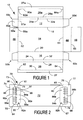
- the first blank is shown in Figure 1 and shows outer blank 10 comprising a plurality of panels for forming the outer tray.
- outer blank 10 comprising a plurality of panels for forming the outer tray.
- There comprises first outer side wall panel 12, base panel 14, and second outer side wall panel 16 hingedly connected together in series along foldlines 18, 20 respectively.
- There further comprises an inner side wall structure hingedly connected to side wall panels 16 and 12 respectively along fold lines 32 and 32a.
- inner side wall structure there comprises a securing flap 27 and an inner side wall panel 26 hingedly connected together along fold line 30.
- inner side wall panel 26 is connected to outer side wall panel, although in the illustrated embodiment, there may further comprise spacer panel 24 hingedly interconnecting outer side wall panel 16 to inner side wall panel 26 along fold lines 32 and 28 respectively.
- the article retention structure 82a is formed from at least part of inner base panel 72 and, preferably, extends into inner end wall panel 74 being hingedly interconnected to the aforementioned panels along fold lines 84a and fold line 90a.
- the article retention structure 82a is otherwise separated from inner base panel 72 and wall panel 74 along proposed cut lines 94 and 96 which extend between the opposed ends of fold lines 84a and 90a.
- the article retention structure comprises a riser panel 86a and a tread panel 88a hingedly connected together along interrupted fold line 92a. In use, the article retention structure 82a forms a step.
- the inner end wall panels 74, 76 are wider than base panel 72 such that the opposite ends edges 73, 75; 77, 79 of the end wall panels project outwardly beyond the side edges of the base panel and outer end wall panels 44, 46.
- Such an arrangement allows the end edges to be engaged with the inner side panels 26, 26a respectively in a set up tray, to retain the inner end panels in position whilst the retention structures 82 are formed from the inner base and inner end panels 72; 74, 76.
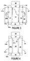
- the construction of the tray from the blank shown in Figure 1 is described by reference to Figures 3, 4 and 5. It is envisaged that the construction of a flat collapsed tray and final construction and loading of the tray of the present invention can be formed by a series of sequential folding and gluing operations which can be performed in one or more straight line machines, so that the tray is not required to be rotated or inverted to complete its construction.
- the folding process is not limited to that described below and can be altered according to particular manufacturing requirements.
- the side walls are first constructed, as illustrated in Figures 3 and 4 whereby the inner side wall structures of the outer tray are folded inwardly in direction X and Y, shown in Figure 3 along fold lines 32 and 32a respectively and are secured to the base panel 14.
- securing panels 27 and 27a are secured to base wall panel 14 by glue or other suitable securing means known in the art.
- the tray is in a flat collapsed form as shown in Figure 4 to be supplied to the user so it can be erected.
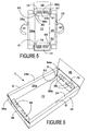
- the outer side wall panels 12 and 16 are folded inwardly in directions W and W 1 respectively, which causes the inner and outer side wall panels to be separated and spaced therefrom by the spacer panels 24 and 24a, and because fold lines 20 and 30 are spaced.
- This action causes the tabs 38, 40; 38a, 40a to become separated from the respective inner side wall panels 26 and 26a thereby to protrude inwardly with respect to the side walls, as shown in Figures 5 and 6.
- the insert 70 is prevented from being separated from the tray T by the protruding tabs 61, 63, 65, 67 that are inserted into the corresponding adjacent slots S formed by cut lines 62, 62a, 64, 64a, shown in Figure 6.
- the outer side walls 12, 16 continue to be pushed inwardly in directions W and W 1 ( Figure 5) until the side wall panels are placed in an erected condition.
- the inner and outer side wall panels 16, 26; 12, 26a of the tray T are in a substantially perpendicular arrangement with respect to the base panel 14, as shown in Figure 6.
- the ends of the tray T is constructed whereby the inner and outer end wall panels 72, 46 and 44, 76 are folded inwardly together along fold lines 94 and 50 respectively and thereafter the end securing flaps 56 are secured to the outer face of the end wall panels by glue or other suitable means known in the art.
- the inner end panels 72, 76 are folded inwardly first, then securing flaps are folded inwardly to be secured to the outer face of the inner end panels, or as the case may be to the inner face of outer end panels 44, 46.
- the tray is prevented from moving laterally with respect to the outer tray T because the edges of the inner end wall panels 72 and 76 extend beyond the inner side walls 26, 26a of the inner tray and to abut the end edges 73, 75, 77, 79 of the side wall panels.
- the tray T is in a set up condition ready to receive an article, as shown in Figure 11.
- One or more articles are placed on the inner tray and are retained by the article retaining structure.
- a tray T for holding foodstuff or the like is provided which tray is formed from paperboard or like foldable sheet material and can be erected from a flat collapsed condition into a position of use and includes a double skinned zone around the side and end walls and the base wall to provide a void to receive excess liquid or exudates.
- the tray can be erected from a flat collapsed condition into a position of use and further comprises an article retention structure struck from an end portion of inner base panel such that a part of the end portion along the inner side panel remain flat with the outer base panel and wherein an engaging tab is formed along the part of the end portion to engage the end slot in the inner side panel.
- each void could be adapted to receive suitable absorbing material, for example absorbing stamp or bag, preferably during the initial set up process or by the application of absorbing polymer gel, for example polyacrylamide, during the set up or gluing steps of carton construction.
- suitable absorbing material for example absorbing stamp or bag
- polymer gel for example polyacrylamide
- FIG. 7 it is formed from a unitary blank and is similar to the first embodiment, so like parts have been designated by the same reference with the prefix '1'. Therefore only the differences will be described in any greater detail with reference to Figure 7.
- the insert is connected to inner side wall panel 126 along fold line 130.
- the engaging tabs 165, 167 are formed on one side edge of the insert.
- the slots are formed from recesses 179 and 181.
- the tray is constructed in very similar manner to the first embodiment, so only the differences will be described.
- the inner side wall panel 126a is folded inwardly in direction X 1 along fold line 132a and securing flap 127a is secured to base panel 114 as shown in Figure 8. Thereafter, the insert and inner side wall pand 126 are folded inwardly in direction Y 1 along fold line 132 as illustrated in Figure 9, so the tray is in a flat collapsed condition ready to be supplied to an end user as shown in Figure 10.
- the side walls and end walls are constructed and secured together as described above to produce a tray shown in Figure 11 ready to be loaded with one or more articles.
- the two ply embodiment hereinbefore described provides a structure that is strengthened to retain foodstuff.
- the use of paperboard material provides an "environmentally friendly" alternative to trays formed from plastics material and the tray can include printed matter for marketing purposes, as the board can be recycled.
- the arrangement of the panels for the tray in the embodiment described above allows printed matter to be placed on the internal and external side and end walls of the tray.
- a further advantage of the arrangement described above is that the material used for the tray and insert can differ.
- a different caliper of paper can be used, or the insert could be a food grade material, whilst the outer tray could be a material that is more suited to the application of printed matter.
- hinged connection should not be construed as necessarily referring to a single fold line only: indeed it is envisaged that hinged connection can be formed from one or more of one of the following, a score line, a frangible line or a fold line, without departing from the scope of invention.
Landscapes
- Engineering & Computer Science (AREA)
- Mechanical Engineering (AREA)
- Cartons (AREA)
Abstract
Description
Such an arrangement allows the end edges to be engaged with the
Claims (27)
- A tray for holding foodstuff or the like which tray is formed from paperboard or like foldable sheet material and can be erected from a flat collapsed condition into a position of use, the tray comprising a plurality of panels for forming a base, opposed side and end walls wherein the panels forming the tray are a composite structure comprising inner and outer panels forming the base, side and end walls, characterized in that part of an outer portion of inner base panel remains flat with the outer base panel and in that an engaging tab is formed along the part of the outer portion to engage a slot formed in the inner side panel.
- A tray as claimed in claim 1 wherein the engaging tab is adapted to retain the inner base panel in face contacting arrangement with the outer base panel.
- A tray as claimed in claim 1 or claim 2 wherein there further comprises an article retention structure struck at least in part from said outer portion of the inner base panel.
- A tray as claimed in claim 3 wherein the engaging tab is located at the outer portion of the inner base panel resists the load of articles held by the retention structure to hold the retention structure in a set up position.
- A tray as claimed in claim 3 or claim 4 wherein an outer portion of the inner end panel is retained by the inner side panel to retain the inner end panel in a set up condition while the retention structure is formed.
- A tray as claimed in any of claims 1 to 5 wherein the inner panels forming the base, side and end walls are provided by an insert
- A tray for holding foodstuff or the like which tray is formed from paperboard or like foldable sheet material and can be erected from a flat collapsed condition into a position of use, the tray comprising a plurality of panels for forming a base, opposed side and end walls wherein the panels forming the tray are a composite structure comprising inner and outer panels forming the base, side and end walls and an article retention structure struck at least in part from said outer portion of the inner base panel characterized in that an outer portion of the inner end panel is retained by the inner side panel to retain the inner end panel in a set up condition while the retention structure is formed.
- A tray according to any one of claims 1 to 7 further comprising a beam support structure formed along one side of the tray from the inner side panel foldably connected along a first fold line to the outer base panel and the outer side panel foldably connected along a second fold line to the outer base panel, wherein the first and second fold lines are offset such that the inner side panel extends upwardly to abut the outer end panel thereby to define the beam.
- A tray according to claim 8 wherein there further comprises a spacer panel hingedly interconnecting the inner and outer end panels to form the beam.
- A tray as claimed in any preceding claim further comprising a deformable portion hinged to the adjacent side and end panels between the base panel and the securing means, said deformable portion deformed when the tray is erected to provide a ply of material spanning the side and end panels to inhibit egress of fluid from the base panel at each said corner of the tray.
- A tray as claimed in claim 10 wherein the deformable portion is hingedly connected to the adjacent side panel by a fold line in an obtuse angular relationship with the fold line connecting the end panel and base panel.
- A tray as claimed in claim 10 or claim 11 wherein said securing means comprises a flap hingedly connected to one of said side and end panels and foldable to be superposed with the other said side and end panels to be secured therewith, which flap is severed from the deformable portion.
- A tray as claimed in any of claims 10 to 12 wherein said deformable portion is provided by a gusset panel.
- A tray as claimed in any preceding claim wherein the inner and outer walls forming the base and the side and end walls define one or more skinned zones providing one or more voids wherein means are provided to give fluid communication between the internal surface of the base and said void so that fluid present in the tray can drain into the voids in the base and in the side and end walls.
- A tray according to claim 14 wherein said fluid communication means comprises a plurality of perforations distributed along at least one edge of the inner base wall.
- A tray according to claim 14 or claim 15 wherein the voids include absorbing means to absorb said liquid.
- A blank for forming a tray for holding foodstuff or the like which tray is formed from paperboard or like foldable sheet material comprising a plurality of panels for forming an outer base, opposed side and end walls and an insert comprising a plurality of panel forming the inner base, side and end walls characterised in that there further comprises an article retention structure struck from an outer portion of inner base panel such that a part of the outer portion along the inner side panel remain flat with the outer base panel in a set up condition and wherein an engaging tab is formed along the part of the end portion to engage the end slot in the inner side panel.
- A blank as claimed in claim 17 wherein the engaging tab is located at the outer portion of the inner base wall panel.
- A blank as claimed in claim 17 or claim 18 wherein the tab is adapted to retain the inner base panel in face contacting arrangement with the outer base panel, in a set up condition.
- A blank according to any of claims 17 to 19 further comprising a beam support structure formed along one side of the set up tray from the inner side panel foldably connected along a first fold line to the outer base panel and the outer side panel foldably connected along a second fold line to the outer base panel, wherein the first and second fold lines are offset such that the inner side panel extends upwardly to abut the outer end panel thereby to define the beam in a set up tray.
- A blank as claimed in any of claims 17 to 20 further comprising a deformable portion hinged to the adjacent side and end panels between the base panel and the securing means, said deformable portion deformed when the tray is erected to provide a ply of material spanning the side and end panels to inhibit egress of fluid from the base panel at each said corner of the tray.
- A blank as claimed in claim 21 wherein the deformable portion is hingedly connected to the adjacent side panel by a fold line in an obtuse angular relationship with the fold line connecting the end panel and base panel.
- The blank as claimed in any of claims 17 to 22 wherein said deformable portion is provided by a gusset panel.
- A blank according to claim 23 wherein there further comprises a plurality of perforations distributed along at least one edge of the base.
- A method of forming a tray from a blank as claimed in any of claims 17 to 24, which method comprises the steps: -(i) forming a two ply base, end and side wall structures;(ii) folding the side walls out of alignment with the base such that the inner end panels and article retention structure are automatically erected in response to folding the opposed side walls towards each other; and(iii) folding the outer end panels to abut a portion of the inner end walls to be secured to the side walls thereby to complete construction of the tray.
- The method as claimed in claim 25 wherein the gusset panels are automatically folded inwardly and upwardly in response to folding the side walls in step (ii).
- A method as claimed in claim 25 or claim 26 wherein the gusset panels arepre-folded prior to final folding of the side and end walls.
Applications Claiming Priority (2)
| Application Number | Priority Date | Filing Date | Title |
|---|---|---|---|
| GB0124542 | 2001-10-12 | ||
| GB0124542A GB0124542D0 (en) | 2001-10-12 | 2001-10-12 | Tray container and blank |
Publications (2)
| Publication Number | Publication Date |
|---|---|
| EP1302403A2 true EP1302403A2 (en) | 2003-04-16 |
| EP1302403A3 EP1302403A3 (en) | 2004-03-17 |
Family
ID=9923726
Family Applications (1)
| Application Number | Title | Priority Date | Filing Date |
|---|---|---|---|
| EP02022779A Withdrawn EP1302403A3 (en) | 2001-10-12 | 2002-10-11 | Tray container and blank |
Country Status (2)
| Country | Link |
|---|---|
| EP (1) | EP1302403A3 (en) |
| GB (1) | GB0124542D0 (en) |
Cited By (2)
| Publication number | Priority date | Publication date | Assignee | Title |
|---|---|---|---|---|
| GB2511728A (en) * | 2013-01-16 | 2014-09-17 | Ds Smith Packaging Ltd | A box and a blank or kit of parts for creating said box |
| CN107487512A (en) * | 2017-08-18 | 2017-12-19 | 铜陵市南亚包装有限责任公司 | One kind is packed for novel double-layer cardboard |
Family Cites Families (8)
| Publication number | Priority date | Publication date | Assignee | Title |
|---|---|---|---|---|
| US736727A (en) * | 1902-10-22 | 1903-08-18 | Morris Hirsch | Folding box. |
| GB656015A (en) * | 1948-12-08 | 1951-08-08 | Taylowe Ltd | Improvements in folding or collapsible cardboard boxes |
| US2465169A (en) * | 1948-12-13 | 1949-03-22 | Richard P O'connor | Display box |
| US2758781A (en) * | 1953-08-12 | 1956-08-14 | Lawrence Paper Co | Container |
| SE385458B (en) * | 1973-06-20 | 1976-07-05 | Esseltepack Ab | PACKAGING AND EXHIBITION TRAINS |
| FR2685906B1 (en) * | 1992-01-07 | 1995-03-31 | Sca Emballage France | SEALED CARDBOARD TRAY. |
| DE9202098U1 (en) * | 1992-02-15 | 1992-08-13 | Europa Carton Ag, 2000 Hamburg | Container, in particular in the form of a cuboid box with at least two cuts made of foldable and collapsible material |
| GB9819925D0 (en) * | 1998-09-14 | 1998-11-04 | Mead Corp | A tray container and blank |
-
2001
- 2001-10-12 GB GB0124542A patent/GB0124542D0/en not_active Ceased
-
2002
- 2002-10-11 EP EP02022779A patent/EP1302403A3/en not_active Withdrawn
Cited By (2)
| Publication number | Priority date | Publication date | Assignee | Title |
|---|---|---|---|---|
| GB2511728A (en) * | 2013-01-16 | 2014-09-17 | Ds Smith Packaging Ltd | A box and a blank or kit of parts for creating said box |
| CN107487512A (en) * | 2017-08-18 | 2017-12-19 | 铜陵市南亚包装有限责任公司 | One kind is packed for novel double-layer cardboard |
Also Published As
| Publication number | Publication date |
|---|---|
| EP1302403A3 (en) | 2004-03-17 |
| GB0124542D0 (en) | 2001-12-05 |
Similar Documents
| Publication | Publication Date | Title |
|---|---|---|
| US7216797B2 (en) | Tray container and blank | |
| US7690507B2 (en) | Package for containers | |
| US7080772B2 (en) | Tray container and blank | |
| US6568585B2 (en) | Carton and carton blank | |
| US6386439B2 (en) | Tray container and blank | |
| EP1113969B1 (en) | A tray container and blank | |
| EP1343696B1 (en) | A tray container and blank | |
| EP1615829B1 (en) | Fully enclosed carton and blank | |
| EP1235717B1 (en) | A tray container and blank | |
| EP1119499B1 (en) | A tray container and blank | |
| US7322464B2 (en) | Fully enclosed carton and blank | |
| EP1163159B1 (en) | Product encircling band and carton | |
| EP1129013B1 (en) | A tray container and blank | |
| CA2380773C (en) | Carton and carton blank | |
| EP1415923A2 (en) | A tray container and blank | |
| EP1141377B1 (en) | Carton and carton blank | |
| WO2003059758A1 (en) | A carton and blank | |
| WO2004063027A2 (en) | Tray container and blank |
Legal Events
| Date | Code | Title | Description |
|---|---|---|---|
| PUAI | Public reference made under article 153(3) epc to a published international application that has entered the european phase |
Free format text: ORIGINAL CODE: 0009012 |
|
| AK | Designated contracting states |
Designated state(s): AT BE BG CH CY CZ DE DK EE ES FI FR GB GR IE IT LI LU MC NL PT SE SK TR |
|
| AX | Request for extension of the european patent |
Extension state: AL LT LV MK RO SI |
|
| RAP1 | Party data changed (applicant data changed or rights of an application transferred) |
Owner name: MEADWESTVACO PACKAGING SYSTEMS LLC |
|
| PUAL | Search report despatched |
Free format text: ORIGINAL CODE: 0009013 |
|
| AK | Designated contracting states |
Kind code of ref document: A3 Designated state(s): AT BE BG CH CY CZ DE DK EE ES FI FR GB GR IE IT LI LU MC NL PT SE SK TR |
|
| AX | Request for extension of the european patent |
Extension state: AL LT LV MK RO SI |
|
| RIC1 | Information provided on ipc code assigned before grant |
Ipc: 7B 65D 81/26 B Ipc: 7B 65D 5/50 A |
|
| 17P | Request for examination filed |
Effective date: 20040915 |
|
| AKX | Designation fees paid |
Designated state(s): AT BE BG CH CY CZ DE DK EE ES FI FR GB GR IE IT LI LU MC NL PT SE SK TR |
|
| STAA | Information on the status of an ep patent application or granted ep patent |
Free format text: STATUS: THE APPLICATION IS DEEMED TO BE WITHDRAWN |
|
| 18D | Application deemed to be withdrawn |
Effective date: 20070501 |