EP1302399A1 - Passive deployment readiness indicator for aircraft evacuation slide - Google Patents
Passive deployment readiness indicator for aircraft evacuation slide Download PDFInfo
- Publication number
- EP1302399A1 EP1302399A1 EP02013685A EP02013685A EP1302399A1 EP 1302399 A1 EP1302399 A1 EP 1302399A1 EP 02013685 A EP02013685 A EP 02013685A EP 02013685 A EP02013685 A EP 02013685A EP 1302399 A1 EP1302399 A1 EP 1302399A1
- Authority
- EP
- European Patent Office
- Prior art keywords
- escape slide
- slide
- inflatable
- fully deployed
- lanyard
- Prior art date
- Legal status (The legal status is an assumption and is not a legal conclusion. Google has not performed a legal analysis and makes no representation as to the accuracy of the status listed.)
- Granted
Links
- 230000000007 visual effect Effects 0.000 claims abstract description 19
- 230000007704 transition Effects 0.000 description 18
- 239000004744 fabric Substances 0.000 description 4
- IJGRMHOSHXDMSA-UHFFFAOYSA-N Atomic nitrogen Chemical compound N#N IJGRMHOSHXDMSA-UHFFFAOYSA-N 0.000 description 2
- CURLTUGMZLYLDI-UHFFFAOYSA-N Carbon dioxide Chemical compound O=C=O CURLTUGMZLYLDI-UHFFFAOYSA-N 0.000 description 2
- 230000006378 damage Effects 0.000 description 2
- 229920001971 elastomer Polymers 0.000 description 2
- 239000007789 gas Substances 0.000 description 2
- 238000000034 method Methods 0.000 description 2
- 230000002093 peripheral effect Effects 0.000 description 2
- JOYRKODLDBILNP-UHFFFAOYSA-N Ethyl urethane Chemical compound CCOC(N)=O JOYRKODLDBILNP-UHFFFAOYSA-N 0.000 description 1
- 239000000853 adhesive Substances 0.000 description 1
- 230000001070 adhesive effect Effects 0.000 description 1
- 229910002092 carbon dioxide Inorganic materials 0.000 description 1
- 239000001569 carbon dioxide Substances 0.000 description 1
- 239000002131 composite material Substances 0.000 description 1
- 238000010276 construction Methods 0.000 description 1
- 238000007796 conventional method Methods 0.000 description 1
- 230000000694 effects Effects 0.000 description 1
- 239000000806 elastomer Substances 0.000 description 1
- 238000004880 explosion Methods 0.000 description 1
- 239000000463 material Substances 0.000 description 1
- 230000013011 mating Effects 0.000 description 1
- 238000012986 modification Methods 0.000 description 1
- 230000004048 modification Effects 0.000 description 1
- 229910052757 nitrogen Inorganic materials 0.000 description 1
- XLYOFNOQVPJJNP-UHFFFAOYSA-N water Substances O XLYOFNOQVPJJNP-UHFFFAOYSA-N 0.000 description 1
Images


Classifications
-
- B—PERFORMING OPERATIONS; TRANSPORTING
- B64—AIRCRAFT; AVIATION; COSMONAUTICS
- B64D—EQUIPMENT FOR FITTING IN OR TO AIRCRAFT; FLIGHT SUITS; PARACHUTES; ARRANGEMENT OR MOUNTING OF POWER PLANTS OR PROPULSION TRANSMISSIONS IN AIRCRAFT
- B64D25/00—Emergency apparatus or devices, not otherwise provided for
- B64D25/08—Ejecting or escaping means
- B64D25/14—Inflatable escape chutes
-
- A—HUMAN NECESSITIES
- A62—LIFE-SAVING; FIRE-FIGHTING
- A62B—DEVICES, APPARATUS OR METHODS FOR LIFE-SAVING
- A62B1/00—Devices for lowering persons from buildings or the like
- A62B1/20—Devices for lowering persons from buildings or the like by making use of sliding-ropes, sliding-poles or chutes, e.g. hoses, pipes, sliding-grooves, sliding-sheets
Definitions
- This invention relates to emergency evacuation equipment for aircraft.
- this invention relates to an inflatable aircraft evacuation slide.
- a conventional method of quickly evacuating a large number of passengers from an aircraft is to provide multiple emergency exits each of which is equipped with an inflatable evacuation slide. As more and more passenger rows are added, more emergency exits and slides are necessary to ensure the safe evacuation of all passengers. Indeed, in order ensure safe evacuation of all passengers, aviation regulations currently require that emergency exit pairs (one door on each side of the aircraft) be no more than 60 feet apart.
- a disembarking passenger it is not possible for a disembarking passenger to know whether or not the slide is properly deployed without walking out onto the wing to verify.
- evacuating passengers from a wing exit directly onto the wing not only would require the passengers to drop several feet from the exit opening onto a sloping surface, but would require the disembarking passengers to walk to the edge of the wing and peer over the edge to determine that the slide is properly deployed before proceeding down the evacuation slide.
- a substantial number of injuries would be possible at such an exit during the hurried departure of the passengers.
- Prior art evacuation slides have overcome the emergency-exit-to-wing surface drop and wing slope problems by providing a raised stable walkway that is deployed over the wing to provide a substantially horizontal walkway leading up to the head end of an over-wing evacuation slide.
- the problems associated with the aircraft wing obscuring the foot end of the evacuation slide have not been adequately addressed.
- Prior art evacuation slides have relied on the combination of a trained flight attendant and an inflatable pole (sometimes referred to as a "barber pole") to provide a visual indication that the lower end of the evacuation slide has been properly deployed.
- a prior art evacuation slide having a barber pole indicator is disclosed for example in U.S. Patent No. 4,333,546 to Fisher.
- Barber pole visual indicators have a number of disadvantages, including the fact that they use valuable inflation gasses to effect their deployment. Moreover, barber pole visual indicators are not intuitive. Accordingly, if a trained flight attendant is not available to monitor the evacuation, self-disembarking passengers will not know to look for the barber poles to determine the status of the evacuation slide and may attempt to exit the plane before the slide is properly deployed.
- the present invention comprises an inflatable over-the-wing evacuation slide having a readiness indicator the meaning of which is intuitively obvious to an untrained person.
- the slide is provided with an inflatable walkway section projecting from the foot of the wing exit door to a point on the aircraft wing remote from the door.
- the walking surface section is supported at the point remote from the door such that the walking surface presents a generally flat level surface.
- the walking surface also includes an inflatable guard rail attached to the side margins of the inflatable walking surface. Attached to the side of the inflatable guard rail in a position that is clearly visible from the aircraft exit doorway is a visual readiness indicator.
- the visual readiness indicator comprises a conventional red, octagonal "stop" sign that is releasably mounted to the guard rail.
- the stop sign is removed (or obscured) when the evacuation slide has properly deployed.
- removal of the stop sign is effected by attaching one end of a lanyard to the stop sign and the other end of the lanyard to the toe end of the evacuation slide.
- the lanyard is paid out until, at the last stage, when the toe end unfolds the lanyard pulls the stop sign off the guard rail, so that it is no longer visible to a disembarking passenger.
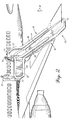
- Fig. 1 shows an inflatable evacuation slide assembly 10 incorporating features of the present invention.
- Inflatable evacuation slide assembly 10 comprises a walkway portion 12, a transition portion 14, which transitions to an evacuation slide 16.
- the evacuation slide 16 includes a head end 18 attached to transition portion 14 and a toe end 20 which extends to the ground.
- the entire inflatable evacuation slide assembly 10 is preferably fabricated from an air impervious material such as a lightweight fabric that has been coated with an elastomer such as rubber or urethane.
- the various parts of the inflatable evacuation slide assembly 10 may be joined together with a suitable adhesive whereby the structure will form a unitary composite structure capable of maintaining its shape during operation.
- the entire structure of the inflatable evacuation slide assembly 10 is preferably formed such that all of the chambers comprising the structure are interconnected pneumatically, such that a single pressurized gas source, such as compressed carbon dioxide, nitrogen, a pyrotechnic gas generator or combination thereof may be utilized for its deployment.
- the main body of walkway portion 12 is constructed of a predetermined number of parallel tubes (not shown) running the length of walkway portion 12.
- the interconnected tubes provide a stable rigid surface upon which passengers may walk when traversing the wing from exit door 30 toward transition section 14.
- Walkway portion further comprises inner and outer peripheral tubes 22 and 24, respectively, which provide additional rigidity and in the case of outer peripheral tube 24 provide support for handrail assembly 25.
- Transition portion 14 also comprises a predetermined number of parallel tubes (not shown) together with a fuselage support structure 40 (shown in Fig. 3) which supports transition portion 14, and with it the proximal end of walkway portion 12, above the surface of the aircraft wing.
- the rigid portion of transition portion terminates at head end 18 of evacuation slide 16.
- Evacuation slide comprises lateral tubes 26 and 28 which extend from transition section 14 to the ground.
- a fabric slide 34 is stretched between lateral tubes 26 and 28 to provide a sliding surface for the disembarking passengers.
- Additional guide rails 36, 38 are positioned atop lateral tubes 26 and 28 respectively to prevent descending passengers from sliding off of the upper portion of slide 16.
- Evacuation slide 16 is configured with a series of shear pins such that evacuation slide 16 unrolls in stages from transition section 14 toward the ground.
- Fig. 1 shows evacuation slide 16 having unfurled with the exception of toe end 42 which is still folded against the remainder of foot end 20 of evacuation slide 16.
- Fig. 2 shows evacuation slide 16 fully deployed such that toe end 42 of foot end 20 is extended and in contact with the ground.
- transition portion 14 further includes transition hand rail 27 which makes an approximately 60 degree turn from walkway portion 12 to head end 18 of evacuation slide 16.
- Affixed to web portion 44 of transition hand rail 27 is a readiness indicator 46.
- readiness indicator 46 comprises a familiar red octagonal stop sign made of fabric and removably attached (e.g. with hook and loop fasteners) to web portion 44 of transition hand rail 27.
- Attached to readiness indicator 46 is a lanyard 48 adapted to remove and conceal readiness indicator 46 when evacuation slide 16 is fully deployed in a manner described more fully hereinafter.
- Fig. 3 is a side view of inflatable evacuation slide assembly 10 viewed from the position indicated at reference 3 of Fig. 1.
- Fig. 4 is a side view of inflatable evacuation slide assembly 10 viewed from the position indicated at reference 4 of Fig. 2.
- readiness indicator 46 shown in phantom lines
- Lanyard 48 passes through conduit 52, through sheath 54 and is attached at the far end to readiness indicator 46.
- lanyard 48 is pulled out of toe end opening 56 of sheath 52 which in turn causes lanyard 48 to yank readiness indicator 46 off its mountings to web portion 44 of transition hand rail 27.
- lanyard 48 pulls readiness indicator 46 into sheath 54 where it is both concealed and stowed.
- readiness indicator 46 comprises the universally recognized octagonal stop sign, preferably made of fabric.
- Readiness indicator 46 is attached to web portion 44 of transition hand rail 27 by means of a plurality of patches of hook-and-loop fasteners 56 corresponding to mating patches (not shown) permanently affixed to web portion 44 of transition hand rail 27.
- Use of hook-and-loop fasteners permits readiness indicator 46 to be reliably affixed to web portion 44 while the inflatable evacuation slide assembly is stowed in the aircraft and during deployment, while providing the appropriate releasable attachment such that lanyard 48 is able to remove readiness indicator 46 at the appropriate time.
Landscapes
- Business, Economics & Management (AREA)
- Emergency Management (AREA)
- Engineering & Computer Science (AREA)
- Aviation & Aerospace Engineering (AREA)
- Emergency Lowering Means (AREA)
Abstract
Description
- This invention relates to emergency evacuation equipment for aircraft. In particular, this invention relates to an inflatable aircraft evacuation slide.
- The requirement for reliably evacuating airline passengers in the event of an emergency becomes more important as the size of the aircraft and the number of passengers increases. Emergencies at take-off and landing often demand swift removal of the passengers from the aircraft because of the potential for injuries from fire, explosion, or sinking in water. A conventional method of quickly evacuating a large number of passengers from an aircraft is to provide multiple emergency exits each of which is equipped with an inflatable evacuation slide. As more and more passenger rows are added, more emergency exits and slides are necessary to ensure the safe evacuation of all passengers. Indeed, in order ensure safe evacuation of all passengers, aviation regulations currently require that emergency exit pairs (one door on each side of the aircraft) be no more than 60 feet apart.
- A substantial number of passenger seats are normally located directly over the wing section of most commercial aircraft. Therefore, in order to comply with emergency exit regulations it is necessary to locate emergency doors immediately over the aircraft wing. These over-wing emergency exits require passengers to exit the aircraft by stepping out onto the upper surface of the wing in order to make their way to the evacuation slide. Unfortunately, the passenger deck level of most commercial aircraft is often considerably higher than the upper surface of the wings. Emergency exit doors over the wing sections must therefore be located several feet above the wing. Also, the upper wing surface of the aircraft has a substantial pitch. Worse, because the evacuation slide must extend outwardly from the aircraft, the lower "foot" end of the slide is obscured by the trailing edge of the wing itself. Accordingly, it is not possible for a disembarking passenger to know whether or not the slide is properly deployed without walking out onto the wing to verify. Thus, evacuating passengers from a wing exit directly onto the wing not only would require the passengers to drop several feet from the exit opening onto a sloping surface, but would require the disembarking passengers to walk to the edge of the wing and peer over the edge to determine that the slide is properly deployed before proceeding down the evacuation slide. Obviously, in an emergency a substantial number of injuries would be possible at such an exit during the hurried departure of the passengers.
- Prior art evacuation slides have overcome the emergency-exit-to-wing surface drop and wing slope problems by providing a raised stable walkway that is deployed over the wing to provide a substantially horizontal walkway leading up to the head end of an over-wing evacuation slide. The problems associated with the aircraft wing obscuring the foot end of the evacuation slide, however, have not been adequately addressed. Prior art evacuation slides have relied on the combination of a trained flight attendant and an inflatable pole (sometimes referred to as a "barber pole") to provide a visual indication that the lower end of the evacuation slide has been properly deployed. A prior art evacuation slide having a barber pole indicator is disclosed for example in U.S. Patent No. 4,333,546 to Fisher. Barber pole visual indicators have a number of disadvantages, including the fact that they use valuable inflation gasses to effect their deployment. Moreover, barber pole visual indicators are not intuitive. Accordingly, if a trained flight attendant is not available to monitor the evacuation, self-disembarking passengers will not know to look for the barber poles to determine the status of the evacuation slide and may attempt to exit the plane before the slide is properly deployed.
- Accordingly, what is needed is a readiness indicator for an aircraft evacuation slide that does not consume valuable inflation gasses and would be intuitive to an untrained person.
- The present invention comprises an inflatable over-the-wing evacuation slide having a readiness indicator the meaning of which is intuitively obvious to an untrained person. In one embodiment, the slide is provided with an inflatable walkway section projecting from the foot of the wing exit door to a point on the aircraft wing remote from the door. The walking surface section is supported at the point remote from the door such that the walking surface presents a generally flat level surface. The walking surface also includes an inflatable guard rail attached to the side margins of the inflatable walking surface. Attached to the side of the inflatable guard rail in a position that is clearly visible from the aircraft exit doorway is a visual readiness indicator. In one embodiment, the visual readiness indicator comprises a conventional red, octagonal "stop" sign that is releasably mounted to the guard rail. The stop sign is removed (or obscured) when the evacuation slide has properly deployed. In the illustrative embodiment, removal of the stop sign is effected by attaching one end of a lanyard to the stop sign and the other end of the lanyard to the toe end of the evacuation slide. As the evacuation slide unfurls, the lanyard is paid out until, at the last stage, when the toe end unfolds the lanyard pulls the stop sign off the guard rail, so that it is no longer visible to a disembarking passenger.
- The present invention will be better understood from a reading of the following detailed description, taken in conjunction with the accompanying drawing figures in which like references designate like elements and, in which:
- Fig. 1 is a perspective view of an aircraft equipped with an evacuation slide incorporating features of the present invention with the slide not fully deployed;
- Fig. 2 is a perspective view of an aircraft equipped with an evacuation slide incorporating features of the present invention with the slide fully deployed;
- Fig. 3 is a side view of the evacuation slide of Fig. 1 with the slide not fully deployed;
- Fig. 4 is a side view of the evacuation slide of Fig. 1 in the fully-deployed state;
- Fig. 5 is a partial close-up view of the evacuation slide of Fig. 4; and
- Fig. 6 depicts one embodiment of a visual indicator incorporating features of the present invention.
-
- The drawing figures are intended to illustrate the general manner of construction and are not necessarily to scale. In the detailed description and in the drawing figures, specific illustrative examples are shown and herein described in detail. It should be understood, however, that the drawing figures and detailed description are not intended to limit the invention to the particular form disclosed, but are merely illustrative and intended to teach one of ordinary skill how to make and/or use the invention claimed herein and for setting forth the best mode for carrying out the invention.
- Fig. 1 shows an inflatable
evacuation slide assembly 10 incorporating features of the present invention. Inflatableevacuation slide assembly 10 comprises awalkway portion 12, atransition portion 14, which transitions to anevacuation slide 16. Theevacuation slide 16 includes ahead end 18 attached totransition portion 14 and atoe end 20 which extends to the ground. - The entire inflatable
evacuation slide assembly 10 is preferably fabricated from an air impervious material such as a lightweight fabric that has been coated with an elastomer such as rubber or urethane. The various parts of the inflatableevacuation slide assembly 10 may be joined together with a suitable adhesive whereby the structure will form a unitary composite structure capable of maintaining its shape during operation. The entire structure of the inflatableevacuation slide assembly 10 is preferably formed such that all of the chambers comprising the structure are interconnected pneumatically, such that a single pressurized gas source, such as compressed carbon dioxide, nitrogen, a pyrotechnic gas generator or combination thereof may be utilized for its deployment. - The main body of
walkway portion 12 is constructed of a predetermined number of parallel tubes (not shown) running the length ofwalkway portion 12. The interconnected tubes provide a stable rigid surface upon which passengers may walk when traversing the wing fromexit door 30 towardtransition section 14. Walkway portion further comprises inner and outerperipheral tubes peripheral tube 24 provide support forhandrail assembly 25.Transition portion 14 also comprises a predetermined number of parallel tubes (not shown) together with a fuselage support structure 40 (shown in Fig. 3) which supportstransition portion 14, and with it the proximal end ofwalkway portion 12, above the surface of the aircraft wing. The rigid portion of transition portion terminates athead end 18 ofevacuation slide 16. - Evacuation slide comprises
lateral tubes transition section 14 to the ground. Afabric slide 34 is stretched betweenlateral tubes Additional guide rails lateral tubes slide 16. -
Evacuation slide 16 is configured with a series of shear pins such that evacuation slide 16 unrolls in stages fromtransition section 14 toward the ground. Fig. 1 showsevacuation slide 16 having unfurled with the exception oftoe end 42 which is still folded against the remainder offoot end 20 ofevacuation slide 16. Fig. 2 showsevacuation slide 16 fully deployed such thattoe end 42 offoot end 20 is extended and in contact with the ground. - With reference again to Fig. 1,
transition portion 14 further includestransition hand rail 27 which makes an approximately 60 degree turn fromwalkway portion 12 to head end 18 ofevacuation slide 16. Affixed toweb portion 44 oftransition hand rail 27 is areadiness indicator 46. In the illustrative embodiment of Fig. 1,readiness indicator 46 comprises a familiar red octagonal stop sign made of fabric and removably attached (e.g. with hook and loop fasteners) toweb portion 44 oftransition hand rail 27. Attached toreadiness indicator 46 is alanyard 48 adapted to remove and concealreadiness indicator 46 whenevacuation slide 16 is fully deployed in a manner described more fully hereinafter. - With reference to Figs. 1 and 2, when
evacuation slide 16 is not fully deployed,readiness indicator 46 is displayed so that it is clearly visible to a passenger such aspassenger 50 exiting one of theexit door 30 of the aircraft. Since the red octagonal stop sign is virtually universally recognized, untrained personnel such as apassenger 50 will be alerted to the fact thatevacuation slide 16 is not yet ready to use. As shown in Fig. 2, onceevacuation slide 16 is fully deployed includingtoe end 42 thereof,readiness indicator 46 is removed and concealed, and therefore passengers disembarking the plane will proceed down the now fully deployedevacuation slide 16. - Fig. 3 is a side view of inflatable
evacuation slide assembly 10 viewed from the position indicated atreference 3 of Fig. 1. Similarly, Fig. 4 is a side view of inflatableevacuation slide assembly 10 viewed from the position indicated at reference 4 of Fig. 2. As shown in Fig. 3, whentoe end 42 ofevacuation slide 16 has not yet fully deployed, readiness indicator 46 (shown in phantom lines) is attached toweb portion 44 oftransition hand rail 27 so that it is clearly observable to a passenger exiting the aircraft.Lanyard 48 passes throughconduit 52, throughsheath 54 and is attached at the far end toreadiness indicator 46. As shown in Fig. 4, as the last shear pin (not shown) shears and toe end 42 ofevacuation slide 16 unfurls,lanyard 48 is pulled out of toe end opening 56 ofsheath 52 which in turn causeslanyard 48 to yankreadiness indicator 46 off its mountings toweb portion 44 oftransition hand rail 27. As shown more clearly in Fig. 5, to ensure that readiness indicator is both removed fromweb portion 44 and concealed so that it cannot be seen by a disembarking passenger, in the illustrative embodiment,lanyard 48 pullsreadiness indicator 46 intosheath 54 where it is both concealed and stowed. - As shown in Fig. 6, in the illustrative embodiment,
readiness indicator 46 comprises the universally recognized octagonal stop sign, preferably made of fabric.Readiness indicator 46 is attached toweb portion 44 oftransition hand rail 27 by means of a plurality of patches of hook-and-loop fasteners 56 corresponding to mating patches (not shown) permanently affixed toweb portion 44 oftransition hand rail 27. Use of hook-and-loop fasteners permitsreadiness indicator 46 to be reliably affixed toweb portion 44 while the inflatable evacuation slide assembly is stowed in the aircraft and during deployment, while providing the appropriate releasable attachment such thatlanyard 48 is able to removereadiness indicator 46 at the appropriate time. - Although certain illustrative embodiments and methods have been disclosed herein, it will be apparent from the foregoing disclosure to those skilled in the art that variations and modifications of such embodiments and methods may be made without departing from the spirit and scope of the invention. For example in lieu of an octagonal stop sign which is removed from the passengers view, a permanent sign which is concealed by a cover operated by a lanyard, or a conventional yellow "police tape" stretching across the entrance to transition
portion 14, which is removed by a lanyard are considered within the scope of the present invention. Accordingly, it is intended that the invention shall be limited only to the extent required by the appended claims and the rules and principles of applicable law.
Claims (12)
- An escape slide adapted to be inflated and extended from an elevated supporting surface to a lower supporting surface, said escape slide comprising:an inflatable walkway portion supported by said elevated supporting surface, said inflatable walkway portion including an entrance end and an exit end,an inflatable slide portion extending from said exit end of said inflatable walkway portion to said lower supporting surface, said inflatable slide portion including a distal section in contact with said lower supporting surface when said escape slide is fully inflated; anda readiness indicator observable to a user proximal said entrance end of said walkway portion, said readiness indicator comprising a visual indicator that is deployed and observable to a user proximal said entrance end of said walkway when said escape slide is not fully deployed and is not observable to a user proximal said entrance end of said walkway when said escape slide is fully deployed.
- The escape slide of claim 1, further comprising:an inflatable wall portion, said inflatable wall portion having a wall surface that is observable to a user proximal said entrance end of said walkway, said visual indicator being mounted to said wall surface for observation by said user when said escape slide is not fully deployed.
- The escape slide of claim 2, wherein:said visual indicator comprises a sign attached to said wall surface.
- The escape slide of claim 3, wherein:said visual indicator is releasably attached to said wall surface when said escape slide is in a less than fully deployed condition.
- The escape slide of claim 4, further comprising:a lanyard, said lanyard having a first end attached to said distal section of said inflatable slide portion and a second end operatively attached to said visual indicator, said lanyard operating to detach said visual indicator from said wall surface when said escape slide moves from a less than fully deployed condition to a fully deployed condition.
- The escape slide of claim 3, further comprising:a cover panel moveable from a first position in which said visual indicator is observable to a user proximal said entrance end of said walkway to a second position in which said cover panel conceals said visual indicator, andan actuator for moving said cover panel from said first position to said second position when said escape slide moves from a less tan fully deployed condition to a fully deployed condition.
- The escape slide of claim 6, wherein:said actuator comprises a lanyard, said lanyard having a first end attached to said distal section of said inflatable slide portion and a second end operatively attached to said cover panel, said lanyard operating to move said cover panel to said second position for concealing said visual indicator when said escape slide moves from a less than fully deployed condition to a fully deployed condition.
- An escape slide adapted to be inflated and extended from an elevated supporting surface to a lower supporting surface, said escape slide comprising:an inflatable walkway portion supported above said elevated supporting surface, said inflatable walkway portion including an entrance end and an exit end,an inflatable slide portion extending from said exit end of said inflatable walkway portion to said lower supporting surface, said inflatable slide portion including a distal section in contact with said lower supporting surface when said escape slide is fully inflated;a readiness indicator, said readiness indicator being mounted on said escape slide so as to be observable to a person proximal said entrance end of said walkway portion when said escape slide is not fully deployed; andmeans for obscuring said readiness indicator so that it is not observable to a person proximal said entrance end of said walkway when said escape slide is fully deployed.
- The escape slide of claim 8, wherein:said means for obscuring comprises means for dismounting said readiness indicator from said escape slide.
- The escape slide of claim 9, wherein:said means for dismounting said readiness indicator comprises a lanyard, said lanyard operating to detach said visual indicator from said wall surface when said escape slide moves from a less than fully deployed condition to a fully deployed condition.
- The escape slide of claim 8, wherein:said means for obscuring comprises means for covering said readiness indicator.
- The escape slide of claim 11, wherein:said means for covering comprises a cover panel, said cover panel being operatively attached to a lanyard, said lanyard operating to move said cover panel over said visual indicator when said escape slide moves from a less than fully deployed condition to a fully deployed condition.
Applications Claiming Priority (2)
| Application Number | Priority Date | Filing Date | Title |
|---|---|---|---|
| US09/976,478 US6443259B1 (en) | 2001-10-11 | 2001-10-11 | Passive deployment readiness indicator for aircraft evacuation slide |
| US976478 | 2001-10-11 |
Publications (2)
| Publication Number | Publication Date |
|---|---|
| EP1302399A1 true EP1302399A1 (en) | 2003-04-16 |
| EP1302399B1 EP1302399B1 (en) | 2004-08-25 |
Family
ID=25524136
Family Applications (1)
| Application Number | Title | Priority Date | Filing Date |
|---|---|---|---|
| EP02013685A Expired - Lifetime EP1302399B1 (en) | 2001-10-11 | 2002-06-20 | Passive deployment readiness indicator for aircraft evacuation slide |
Country Status (3)
| Country | Link |
|---|---|
| US (1) | US6443259B1 (en) |
| EP (1) | EP1302399B1 (en) |
| DE (1) | DE60201059T2 (en) |
Families Citing this family (24)
| Publication number | Priority date | Publication date | Assignee | Title |
|---|---|---|---|---|
| US7516832B2 (en) * | 2003-08-20 | 2009-04-14 | Ellenby Technologies, Inc. | Two door electronic safe |
| US6966414B2 (en) * | 2003-12-02 | 2005-11-22 | Goodrich Corporation | Elevated inflatable emergency evacuation slide illumination |
| US7467764B2 (en) * | 2006-10-12 | 2008-12-23 | Goodrich Corporation | Fuselage mounted evacuation slide system |
| US7641149B2 (en) * | 2007-02-13 | 2010-01-05 | The Boeing Company | Multi-exit combined evacuation slide |
| GB0706698D0 (en) * | 2007-04-05 | 2007-05-16 | Brown Edward | Artificial ski slope assembly |
| FR3006995B1 (en) * | 2013-06-14 | 2017-03-17 | Latecoere | AIRPORT DOOR TOBOGGAN ARMING / DISARMING METHOD AND MECHANISM FOR IMPLEMENTING THE SAME |
| US9309002B2 (en) | 2013-10-03 | 2016-04-12 | Air Cruisers Company | Evacuation slide readiness indicating systems |
| US9701411B2 (en) * | 2014-12-10 | 2017-07-11 | Airbus Operations Gmbh | Evacuation slide with a guidance marking |
| US9725181B2 (en) * | 2015-07-17 | 2017-08-08 | Goodrich Corporation | Off wing evacuation system control strap |
| US10160551B2 (en) * | 2015-08-18 | 2018-12-25 | Goodrich Corporation | Translucent illuminated evacuation slide |
| US10000291B2 (en) * | 2015-09-24 | 2018-06-19 | Goodrich Corporation | Aircraft evacuation slide |
| US10351251B2 (en) * | 2016-12-20 | 2019-07-16 | Goodrich Corporation | Audio evacuation system readiness indicator |
| US10793280B2 (en) * | 2017-05-12 | 2020-10-06 | Goodrich Corporation | Evacuation system with wind lift deterrent |
| US10189573B2 (en) * | 2017-05-19 | 2019-01-29 | Goodrich Corporation | Off-wing slide raft |
| US11511871B2 (en) | 2019-09-24 | 2022-11-29 | Goodrich Corporation | Multipurpose readiness indicator for off-wing slide raft |
| US11345478B2 (en) | 2019-09-26 | 2022-05-31 | Goodrich Corporation | Evacuation slide and method of forming evacuation slide having integral cable channel |
| US11745900B2 (en) * | 2019-10-25 | 2023-09-05 | Goodrich Corporation | Health monitoring system of an aircraft evacuation system |
| US11554871B2 (en) * | 2020-01-06 | 2023-01-17 | Goodrich Corporation | Truss strap integrated geometric restraint |
| US11192658B2 (en) * | 2020-01-17 | 2021-12-07 | Goodrich Corporation | Evacuation slide ramp barrier readiness indicator |
| US11745880B2 (en) | 2020-01-17 | 2023-09-05 | Goodrich Corporation | Readiness indicator lights for evacuation slide |
| US11492129B2 (en) * | 2020-01-17 | 2022-11-08 | Goodrich Corporation | Evacuation slide with safety gate readiness indicator |
| US11835179B2 (en) * | 2020-04-16 | 2023-12-05 | Goodrich Corporation | Systems and methods for monitoring evacuation assembly charge cylinders |
| US12134479B2 (en) | 2021-12-03 | 2024-11-05 | Goodrich Corporation | Readiness indicator light system having projection light for evacuation slide |
| US12509232B2 (en) | 2023-09-26 | 2025-12-30 | The Boeing Company | Aircraft evacuation slides |
Citations (2)
| Publication number | Priority date | Publication date | Assignee | Title |
|---|---|---|---|---|
| US4333546A (en) | 1980-02-19 | 1982-06-08 | The B. F. Goodrich Company | Escape slide |
| GB2322108A (en) * | 1996-11-25 | 1998-08-19 | Ian Trevor Hopper | Reusable inflatable escape slide |
Family Cites Families (3)
| Publication number | Priority date | Publication date | Assignee | Title |
|---|---|---|---|---|
| US5738303A (en) * | 1995-05-15 | 1998-04-14 | The Boeing Company | Mechanism for arming, disarming and activating airplane emergency slide evacuation systems |
| US5710543A (en) * | 1996-05-28 | 1998-01-20 | Moore; George David | Emergency warning device and method |
| US5848488A (en) * | 1997-06-07 | 1998-12-15 | Interstate Graphics | Hanging sign |
-
2001
- 2001-10-11 US US09/976,478 patent/US6443259B1/en not_active Expired - Lifetime
-
2002
- 2002-06-20 DE DE60201059T patent/DE60201059T2/en not_active Expired - Lifetime
- 2002-06-20 EP EP02013685A patent/EP1302399B1/en not_active Expired - Lifetime
Patent Citations (2)
| Publication number | Priority date | Publication date | Assignee | Title |
|---|---|---|---|---|
| US4333546A (en) | 1980-02-19 | 1982-06-08 | The B. F. Goodrich Company | Escape slide |
| GB2322108A (en) * | 1996-11-25 | 1998-08-19 | Ian Trevor Hopper | Reusable inflatable escape slide |
Also Published As
| Publication number | Publication date |
|---|---|
| DE60201059T2 (en) | 2005-09-22 |
| EP1302399B1 (en) | 2004-08-25 |
| US6443259B1 (en) | 2002-09-03 |
| DE60201059D1 (en) | 2004-09-30 |
Similar Documents
| Publication | Publication Date | Title |
|---|---|---|
| US6443259B1 (en) | Passive deployment readiness indicator for aircraft evacuation slide | |
| US9309002B2 (en) | Evacuation slide readiness indicating systems | |
| US6523539B2 (en) | Self-elongating oxygen hose for stowable aviation crew oxygen mask | |
| US6769647B2 (en) | Automatic inflation system for evacuation slide | |
| US4846422A (en) | Single piece evacuation system for aircraft or the like | |
| EP1911674B1 (en) | Fuselage mounted evacuation slide system | |
| EP0893343B1 (en) | Inflatable escape slide assembly | |
| US11708167B2 (en) | Multipurpose readiness indicator for off-wing slide raft | |
| US4332049A (en) | Escape slide and protective shield | |
| US3102623A (en) | Escape slide | |
| EP0636542A1 (en) | Inflatable slide raft assembly | |
| US4013247A (en) | Mechanical support apparatus for the stabilization of an inflatable escape slide | |
| EP1431178B1 (en) | Evacuation slide with leading edge spoiler | |
| US11492129B2 (en) | Evacuation slide with safety gate readiness indicator | |
| US3845920A (en) | Inflatable evacuation ramp | |
| US10000292B1 (en) | Multipurpose lane divider for evacuation slide | |
| US11192658B2 (en) | Evacuation slide ramp barrier readiness indicator | |
| US12134479B2 (en) | Readiness indicator light system having projection light for evacuation slide | |
| US7191869B1 (en) | Slide to safety emergency evacuation | |
| US12509232B2 (en) | Aircraft evacuation slides | |
| EP3816051A1 (en) | Integrated truss restraint | |
| EP4190697B1 (en) | Readiness indicator light system having projection light for evacuation slide | |
| CA2369188A1 (en) | Emergency evacuation system | |
| US11066177B2 (en) | Canopy support apparatus |
Legal Events
| Date | Code | Title | Description |
|---|---|---|---|
| PUAI | Public reference made under article 153(3) epc to a published international application that has entered the european phase |
Free format text: ORIGINAL CODE: 0009012 |
|
| AK | Designated contracting states |
Designated state(s): AT BE CH CY DE DK ES FI FR GB GR IE IT LI LU MC NL PT SE TR |
|
| AX | Request for extension of the european patent |
Extension state: AL LT LV MK RO SI |
|
| 17P | Request for examination filed |
Effective date: 20031001 |
|
| AKX | Designation fees paid |
Designated state(s): DE FR |
|
| GRAP | Despatch of communication of intention to grant a patent |
Free format text: ORIGINAL CODE: EPIDOSNIGR1 |
|
| GRAS | Grant fee paid |
Free format text: ORIGINAL CODE: EPIDOSNIGR3 |
|
| GRAA | (expected) grant |
Free format text: ORIGINAL CODE: 0009210 |
|
| AK | Designated contracting states |
Kind code of ref document: B1 Designated state(s): DE FR |
|
| REG | Reference to a national code |
Ref country code: IE Ref legal event code: FG4D |
|
| REF | Corresponds to: |
Ref document number: 60201059 Country of ref document: DE Date of ref document: 20040930 Kind code of ref document: P |
|
| LTIE | Lt: invalidation of european patent or patent extension |
Effective date: 20040825 |
|
| ET | Fr: translation filed | ||
| PLBE | No opposition filed within time limit |
Free format text: ORIGINAL CODE: 0009261 |
|
| STAA | Information on the status of an ep patent application or granted ep patent |
Free format text: STATUS: NO OPPOSITION FILED WITHIN TIME LIMIT |
|
| 26N | No opposition filed |
Effective date: 20050526 |
|
| REG | Reference to a national code |
Ref country code: FR Ref legal event code: PLFP Year of fee payment: 15 |
|
| REG | Reference to a national code |
Ref country code: FR Ref legal event code: PLFP Year of fee payment: 16 |
|
| REG | Reference to a national code |
Ref country code: FR Ref legal event code: PLFP Year of fee payment: 17 |
|
| PGFP | Annual fee paid to national office [announced via postgrant information from national office to epo] |
Ref country code: DE Payment date: 20190521 Year of fee payment: 18 |
|
| PGFP | Annual fee paid to national office [announced via postgrant information from national office to epo] |
Ref country code: FR Payment date: 20190522 Year of fee payment: 18 |
|
| REG | Reference to a national code |
Ref country code: DE Ref legal event code: R119 Ref document number: 60201059 Country of ref document: DE |
|
| PG25 | Lapsed in a contracting state [announced via postgrant information from national office to epo] |
Ref country code: FR Free format text: LAPSE BECAUSE OF NON-PAYMENT OF DUE FEES Effective date: 20200630 |
|
| PG25 | Lapsed in a contracting state [announced via postgrant information from national office to epo] |
Ref country code: DE Free format text: LAPSE BECAUSE OF NON-PAYMENT OF DUE FEES Effective date: 20210101 |