EP1302123B1 - Rolling suitcase with handle system - Google Patents
Rolling suitcase with handle system Download PDFInfo
- Publication number
- EP1302123B1 EP1302123B1 EP01830638A EP01830638A EP1302123B1 EP 1302123 B1 EP1302123 B1 EP 1302123B1 EP 01830638 A EP01830638 A EP 01830638A EP 01830638 A EP01830638 A EP 01830638A EP 1302123 B1 EP1302123 B1 EP 1302123B1
- Authority
- EP
- European Patent Office
- Prior art keywords
- suitcase
- key
- elements
- seats
- handle
- Prior art date
- Legal status (The legal status is an assumption and is not a legal conclusion. Google has not performed a legal analysis and makes no representation as to the accuracy of the status listed.)
- Expired - Lifetime
Links
- 238000005096 rolling process Methods 0.000 title claims abstract description 26
- 230000005540 biological transmission Effects 0.000 claims description 30
- 238000003780 insertion Methods 0.000 claims description 4
- 230000037431 insertion Effects 0.000 claims description 4
- 230000003014 reinforcing effect Effects 0.000 claims description 3
- 210000003484 anatomy Anatomy 0.000 claims description 2
- 230000005484 gravity Effects 0.000 description 4
- 239000000463 material Substances 0.000 description 4
- 230000009471 action Effects 0.000 description 3
- 230000000694 effects Effects 0.000 description 3
- 238000000605 extraction Methods 0.000 description 3
- 230000007246 mechanism Effects 0.000 description 3
- 230000006978 adaptation Effects 0.000 description 2
- 230000008901 benefit Effects 0.000 description 2
- 230000000284 resting effect Effects 0.000 description 2
- 230000008878 coupling Effects 0.000 description 1
- 238000010168 coupling process Methods 0.000 description 1
- 238000005859 coupling reaction Methods 0.000 description 1
- 230000004438 eyesight Effects 0.000 description 1
- 210000003127 knee Anatomy 0.000 description 1
- 210000002414 leg Anatomy 0.000 description 1
- 239000002184 metal Substances 0.000 description 1
- 230000004048 modification Effects 0.000 description 1
- 238000012986 modification Methods 0.000 description 1
- 230000000087 stabilizing effect Effects 0.000 description 1
- 238000005728 strengthening Methods 0.000 description 1
Images







Classifications
-
- A—HUMAN NECESSITIES
- A45—HAND OR TRAVELLING ARTICLES
- A45C—PURSES; LUGGAGE; HAND CARRIED BAGS
- A45C13/00—Details; Accessories
- A45C13/26—Special adaptations of handles
- A45C13/262—Special adaptations of handles for wheeled luggage
-
- A—HUMAN NECESSITIES
- A45—HAND OR TRAVELLING ARTICLES
- A45C—PURSES; LUGGAGE; HAND CARRIED BAGS
- A45C13/00—Details; Accessories
- A45C13/26—Special adaptations of handles
- A45C13/262—Special adaptations of handles for wheeled luggage
- A45C2013/265—Special adaptations of handles for wheeled luggage the handle being adjustable in rotation to a towing element
Definitions
- the present invention relates to a handle system for suitcases, bags and the like, in particular of the type provided with wheels in order to facilitate rolling of said suitcases over a support surface.
- a rolling suitcase is in contact both with the hand of the person transporting the suitcase and with the support surface on which the suitcase rolls by means of rollers.
- a first indispensable requirement consists in adaptation to the individual height of the person transporting the suitcase.
- a rolling suitcase may be pulled along or pushed and its position with respect to the body of the person transporting it should in theory satisfy a large number of requirements which vary depending on the situation and are often difficult to reconcile, for example the overall volume in confined spaces, the freedom of movement of the person transporting the suitcase, control over the direction of travel and the dynamic stability of the movement.
- the first type of handle of the known art consists in a handle made of flexible material which is usually fixed to one of the narrow sides of the suitcase in the direction of travel. Owing to the flexibility of the material, the handle adapts itself to the inclination of the hand of the person transporting the suitcase and is oriented in the direction of the force exerted by that person. Adaptation to the person's height is achieved by means of inclination and raising, on one side, of the case which therefore rests only on a very narrow base of rollers. This type of handle therefore allows only pulling, and not pushing, of the rolling suitcase.
- the second type of handle of the known art consists in a handle which is made of rigid material and can be extracted from one of the wide sides of the suitcase and which allows pulling of the suitcase in an inclined position resting on a very wide base of rollers.
- the rigidity of the connection between the handle and the suitcase, as well as the greater width of the roller base improves both the lateral stability of the suitcase and the control over the direction of movement.
- a first drawback of the handles described above consists in the fact that they allow movement of a rolling suitcase only in a predefined configuration which very often is not suitable for particular situations, such as alternation between pulling and pushing or movement within very confined spaces such as lifts, public transport vehicles and the like.
- a second drawback consists in the fact that the handle systems of the known art do not allow an advantageous control over the play between the forces acting on the suitcase.
- the handle systems of the known art do not allow an advantageous control over the play between the forces acting on the suitcase.
- Well-known consequences of this are a wavering movement and overturning of the suitcase.
- rigid and extractable handles Although allowing a greater lateral stability and improved control over the direction of travel of the rolling suitcase compared to the abovementioned flexible handles, rigid and extractable handles, however, have another drawback, namely that they envisage only one configuration for transportation of the suitcase, in which the suitcase remains inclined and at a distance from the person transporting it. Therefore, in confined spaces it is necessary to lift the suitcase instead of pulling it along.
- a luggage item provide with a telescoping handle assembly comprising a first gripping element and an auxiliary second gripping element which can be rotated in at least two selectable positions, relative to the first gripping element.
- the resulting structure is relatively complex and unsatisfactory.
- the object of the present invention is therefore that of providing a handle system for rolling suitcase which allows the problems mentioned with reference to the known art to be overcome and which ensures easy and safe manoeuvring which can be adapted to the various situations of transportation of the rolling suitcases.
- a handle system is denoted in its entirety by 1.
- Said system 1 is mounted on a suitcase 2 which has a container body 3 with a set of rollers 4 mounted on the base of said container body 3 in order to facilitate rolling of the suitcase 2 along a support surface.
- the handle system 1 comprises a base element 5 connected to said container body 3 as well as an adjustable element 6.
- a first end 6' of said adjustable element 6 is rotatably connected to said base element 5 by an adjusting joint 7 and a second end 6'' thereof forms a handle 8.
- the handle 8 is formed anatomically so that it can be adapted to the form of the human hand.
- said adjustable element 6 has an overall shape which is curved so as to be adapted in the abovementioned locked positions both to the anatomy and to the inclination of the hand of the person who is pushing or pulling the suitcase 2.
- the suitcase 2, or a trolley comprises at least one element for locking the opening of the half-shells forming the suitcase.
- the half-shells arranged next to each other to form the suitcase are kept closed in a releasable manner by means of at least one lock (100) positioned on the facing edges of the latter, in particular along the edges present on the vertical side of the suitcase.
- the suitcase has at least one lock 101 or 102 on the upper side, or width or side opposite to the set of rollers 4 and, preferably, two locks 101 and 102 which, in this position, are particularly easy to use.
- said adjusting joint comprises a pin 9 which is rotatably housed in one or more seats formed in a central lug 10 of said first end 6' of the adjustable element 6 and inserted into holes 11 provided in two lateral lugs 12 formed by said base element 5 so as to create a hinge between said base element 5 and said adjustable element 6.
- the central lug 10 is arranged between the lateral lugs 12, and said central lug 10 and lateral lugs 12 have contact surfaces 13, 13' which are substantially perpendicular with respect to the orientation of the pin 9 and facing each other.
- two key elements 14 are provided, said elements being inserted with one end into first key seats 15 formed in the contact surfaces 13 of the central lug 10 and with the other end into second key seats 15' formed in the contact surfaces 13' of the lateral lugs 12, resulting in a form fit between said base element 5 and said adjustable element 6.
- the key elements 14 are arranged aligned with said pin 9 and have through-holes 16 which are substantially central and which form said seats for the pin 9 and which allow a transverse movement of said key elements 14 along said pin 9.
- the key elements 14 have a substantially tubular shape with radial and/or frontal protuberances 17 which are distributed at intervals along the external circumference of said elements 14, and said first key seats 15 and second key seats 15' have a shape matching the external shape of the key elements 14 so as to provide said form fit between the base element 5 and the adjustable element 6.
- said first key seats 15 have a shape matching the whole key element 14 and said second key seats 15' have a shape matching only said protuberances 17.
- This particular configuration allows sliding of said key elements 14 inside said first key seats 15 as well as locking of said adjustable element 6 in different angular positions by means of insertion of said protuberances 17 in said second key seats 15'.
- the protuberances 17 projecting from said key elements 14 also extend with respect to the orientation of the pin 9 in the radial and longitudinal direction and have a substantially trapezoidal shape viewed in cross section.
- the key elements 14 have four protuberances 17 distributed at an angle of 90° with respect to each other, and the second key seats 15' have respectively four cavities with a matching shape and arrangement. This results in the possibility of adjustment of the adjustable element 6 with respect to the base element 5 in 90° steps.
- the first key seats 15 are connected together inside said central lug 10, forming a single through-seat 15 between said contact surfaces 13, inside which said key elements 14 can be retracted by means of suitable actuating means in order to free said second key seats 15' and disengage said geometric coupling.
- said actuating means comprise an operating pushbutton 18 connected to a longitudinal transmission bar 19, two transverse transmission elements 20 connected to the key elements 14 as well as deviating means 21, 22 which are able to convert the longitudinal movement of said longitudinal transmission bar 19 into a mutual transverse movement of said transmission elements 20 in order to move the two key elements 14 inside said first seat 15 towards or away from each other.
- said deviating means consist of studs 21 which extend from the longitudinal transmission bar 19 and guide channels 22 formed in said transverse transmission elements 20, said guide channels 22 receiving said studs 21 and comprising a section inclined with respect to both the longitudinal and the transverse directions.
- the transverse transmission elements 20 are plates directly formed on the mutually facing sides of said key elements 14.
- each of the key elements 14 has, associated with them, two of said plates 20 which are aligned together with a central space for the pin 9, each of said plates 20 having a guide channel 22 on two opposite sides, respectively.
- the total number of guide channels 22 associated with each individual key element 14 is four.
- the guide channels 22 of both the transverse transmission elements 20 have a substantially specular form with respect to the plane of the longitudinal transmission element 19.
- the guide channels 22 have respectively two outer sections which are parallel and staggered with respect to each other as well as an inclined central section.
- the path of the guide channels 22 is rounded and is substantially in the shape of an S.
- the key elements 14 may be moved away from or towards each other by means of a longitudinal movement, in either direction, of the longitudinal transmission bar 19. The result is that release of the locking action may be performed either by means of pressing or of pulling of the operating element 18.
- the operating pushbutton 18 can be actuated by means of pressure.
- a further embodiment envisages an operating element 18 comprising both a pressing surface and a cavity for the fingers which allows actuation by means of pulling.
- said longitudinal transmission bar 19 is composed of two individual parts which form a double-T section formed by two flanges 19' facing each other and connected by means of a web 19''.
- the plate-like projections 20 of the key elements 14 are received by the interstice between said flanges 19' on the mutually facing surfaces of which said studs 21 are formed, said studs being in turn received and guided by said guide channels 22.
- said longitudinal transmission element 19 is a bar in the form of a double T
- the opening 23 is formed in said web 19''.
- the surface which delimits the side opposite to the operating element 18 of said elongated opening 23 forms a stop surface 24 for said pin 9, preventing the actuating means 18, 19, 20, 21, 22 from coming out of their housing 25 inside the adjustable element 6.
- two helical springs 26 which are pre-tensioned and which abut in special counter-seats formed in said housing 25 are also envisaged, said helical springs 26 acting directly on the operating element 18.
- stop surface 24 prevents the operating element 18 from coming out of the housing 25 owing to the resilient load exerted by the springs 26.
- the base element 5 is not formed as one piece, but has an extractable portion 5', connected to said adjusting joint 7, and a fixed portion 5'', which can be connected to said container body.
- the extractable portion 5' is slidably housed inside a channel 27 formed in the fixed portion 5' and allows adjustment of the distance between the adjusting joint 7 and the container body 3.
- the channel 27 has, viewed in cross section, a substantially elliptical shape and the extractable portion 5' has, viewed in cross section, a substantially elliptical tubular shape matching the cross section of the channel 27.
- the base element 5 has yielding locking means which allow said extractable portion 5' to be locked resiliently in one or more positions inside the channel 27 of said fixed portion 5''.
- yielding locking means preferably comprise one or more stop cavities 28 formed in the surface of said channel 27 and one or more thrusting elements 29 projecting in a yielding manner from the outer surface of said extractable portion 5' and able to snap-engage resiliently into said stop cavities 28.
- the thrusting elements 29 are two metal spheres 28 housed inside a small tube with two openings having a diameter smaller than the diameter of the spheres and pushed towards said openings by means of a pre-tensioned spring arranged between said spheres inside the tube, this tube being arranged at the opposite end to the adjusting joint 7 of the extractable portion 5'.
- the extractable portion 5' has, formed in it, reinforcing ribs which form a central circular tube for strengthening the walls of the elliptical profile.
- the system 1 allows extraction of the extractable portion 5' from the channel 27 of the fixed portion 5'' by means of the handle 8 in order to adapt the handle 8 to the height of the person transporting the suitcase 2.
- the suitcase 2 is brought into an inclined position where it rests with only two rollers 4 on the support surface. Adjustment of the inclination of the adjustable element 6 occurs in three steps: unlocking - adjustment - locking.
- Unlocking is performed without difficulty by means of pushing or pulling of the operating element 18 using the same hand which grips the handle 8, the longitudinal movement of the operating element 18 being transmitted by means of the longitudinal transmission bar 19.
- the studs 21 of the longitudinal transmission bar 19 slide inside the inclined section of the guide channels 22 and convert said longitudinal movement into a mutual transverse movement of the key elements 14, which are fully retracted into the first key seats 15, freeing the second key seats 15' and thus releasing locking of the adjustable element 6 (compare Figures 15a and 15b).
- the adjustment of the adjustable element 6 is performed using the same hand which grips the handle 8.
- a specific rotating action of the hand is not even required because, owing to the gravitational effect, the centre of gravity of the suitcase 2 tends to lower automatically, advantageously stabilizing the suitcase 2 and bringing the adjustable element 6 into the most suitable position for the hand.
- This adjustment is further facilitated thanks to the curved shape of the adjustable element 6 and the anatomical shape of the handle 8 itself.
- Locking of the adjustable element 6 in the optimum position for the person transporting the suitcase is performed by means of reinsertion of the protuberances 17 in the second key seats 15'. Owing to the pre-tensioning of the springs 26, this reinsertion is performed automatically and by means of snap-engagement, as soon as the protuberances 17 and the second key seats 15' are aligned with each other again.
- the angular adjustment of the adjustable element, and therefore of the handle allows the centre of gravity of the suitcase to be lowered in an advantageous manner and the end section of the handle to be oriented substantially in the vertical direction, as shown for example in Figure 14a.
- the system 1 by means of the angular adjustment and linear extraction operations described above, allows the suitcase 2 to be kept in a vertical position, resting on all four rollers. This position allows the suitcase to be moved as close as possible to the person transporting it and to be manoeuvred in very confined spaces, such as lifts and the like.
- the handle 8 is positioned at a point with respect to the suitcase 2, which allows the case to be pushed without the risk of overturning it and moreover ensures a certain freedom of movement for the legs of the person transporting it, as can be seen from Figure 14b.
- the key elements 14 as well as the second key seats 15' are formed and positioned in such a way as to ensure a locked condition of the adjustable element 6, which has proved to be unusually advantageous in terms of stability, safety and ease of use.
- This condition envisages that, in the locked positions of the adjustable element 6, a straight line A which connects the centre of the handle 8 and the centre of the adjusting joint 7 intersects a plane p defined by the base of the suitcase 2, outside of the overall volume of the rollers 4.
- the handle system according to the invention offers numerous advantages.
- the system 1 advantageously allows the centre of gravity of the suitcase to be lowered without changing the distance between person and suitcase.
- the system 1 also allows the suitcase to be pulled along and pushed in very stable, safe and easy conditions.
- the handle system 1 also allows the suitcase to be pushed in very confined spaces, for example lifts, train and underground railway carriages, in such a way that the suitcase always remains in the immediate vicinity and eyesight of the person, does not cause an obstacle and in any case leaves room for the person's knees.
- the curved shape of the adjustable element also ensures a substantially vertical orientation of the handle, both during pulling and pushing of the suitcase.
- the arrangement of the actuating pushbutton 8 allows easy adjustment using the same hand which grips the handle 8, and, as a result of the abovementioned locking and actuating mechanism, the handle system is unusually versatile and reliable.
- tubular and elliptical cross-sectional shape of the extractable portion 5' and the channel 27 ensures an enormous degree of lateral and torsional rigidity which notably improves the lateral stability, the dynamic behaviour and the control over the direction of the rolling suitcase with respect to the systems of the known art.
Landscapes
- Purses, Travelling Bags, Baskets, Or Suitcases (AREA)
- Fittings On The Vehicle Exterior For Carrying Loads, And Devices For Holding Or Mounting Articles (AREA)
Abstract
Description
- The present invention relates to a handle system for suitcases, bags and the like, in particular of the type provided with wheels in order to facilitate rolling of said suitcases over a support surface.
- As is well known, a handle system for rolling suitcases must satisfy very complex requirements.
- During transportation, a rolling suitcase is in contact both with the hand of the person transporting the suitcase and with the support surface on which the suitcase rolls by means of rollers. A first indispensable requirement consists in adaptation to the individual height of the person transporting the suitcase.
- Whereas conventional suitcases are raised from the ground, because they are suspended from the hand of the person transporting them, and are therefore stabilized owing to the effect of gravity, rolling suitcases pose the problem of lateral instability which results in the risk of overturning.
- As regards the modes of use, a rolling suitcase may be pulled along or pushed and its position with respect to the body of the person transporting it should in theory satisfy a large number of requirements which vary depending on the situation and are often difficult to reconcile, for example the overall volume in confined spaces, the freedom of movement of the person transporting the suitcase, control over the direction of travel and the dynamic stability of the movement.
- In the currently known handle systems used for rolling suitcases, substantially two main types may be defined.
- The first type of handle of the known art consists in a handle made of flexible material which is usually fixed to one of the narrow sides of the suitcase in the direction of travel. Owing to the flexibility of the material, the handle adapts itself to the inclination of the hand of the person transporting the suitcase and is oriented in the direction of the force exerted by that person. Adaptation to the person's height is achieved by means of inclination and raising, on one side, of the case which therefore rests only on a very narrow base of rollers. This type of handle therefore allows only pulling, and not pushing, of the rolling suitcase.
- The second type of handle of the known art consists in a handle which is made of rigid material and can be extracted from one of the wide sides of the suitcase and which allows pulling of the suitcase in an inclined position resting on a very wide base of rollers. The rigidity of the connection between the handle and the suitcase, as well as the greater width of the roller base improves both the lateral stability of the suitcase and the control over the direction of movement.
- The handle systems for rolling suitcases of the known art have, however, certain drawbacks with regard to their versatility and ease of use.
- A first drawback of the handles described above consists in the fact that they allow movement of a rolling suitcase only in a predefined configuration which very often is not suitable for particular situations, such as alternation between pulling and pushing or movement within very confined spaces such as lifts, public transport vehicles and the like.
- A second drawback consists in the fact that the handle systems of the known art do not allow an advantageous control over the play between the forces acting on the suitcase. In the particular case of handles made of flexible material it is difficult to control the direction of travel of the suitcase which travels by means of the rollers on the support surface. Well-known consequences of this are a wavering movement and overturning of the suitcase.
- Although allowing a greater lateral stability and improved control over the direction of travel of the rolling suitcase compared to the abovementioned flexible handles, rigid and extractable handles, however, have another drawback, namely that they envisage only one configuration for transportation of the suitcase, in which the suitcase remains inclined and at a distance from the person transporting it. Therefore, in confined spaces it is necessary to lift the suitcase instead of pulling it along.
- To overcome the above limitations WO 99/34701 discloses a luggage item provide with a telescoping handle assembly comprising a first gripping element and an auxiliary second gripping element which can be rotated in at least two selectable positions, relative to the first gripping element.
- The resulting structure is relatively complex and unsatisfactory.
- The object of the present invention is therefore that of providing a handle system for rolling suitcase which allows the problems mentioned with reference to the known art to be overcome and which ensures easy and safe manoeuvring which can be adapted to the various situations of transportation of the rolling suitcases.
- These and other objects are achieved by means of a handle system according to Claim 1.
- A non limiting example of embodiment of the present invention will be described below, with reference to the accompanying drawings, in which:
- Figure 1 is a perspective view of an embodiment of the handle system according to the invention, mounted on a suitcase;
- Figure 2 is a front view of the handle system shown in Figure 1;
- Figure 3 is a side view of the handle system shown in Figure 2;
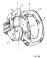
- Figure 4a shows the adjustable element of the handle system according to the invention in a first locked position;
- Figure 4b shows the adjustable element of the handle system according to the invention in a second locked position;
- Figure 5 shows an exploded view of the handle system according to the invention;
- Figure 6 shows right-angle views of the adjustable element of the handle system according to the invention;
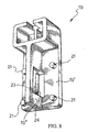
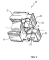
- Figures 7, 8 and 9 show perspective views of the individual elements of the locking mechanism of the handle system according to the invention;
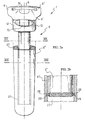
- Figure 10 shows partially sectioned, right-angle views of a base element of the handle system according to the invention;
- Figure 11 shows a cross-sectional view of a detail of the locking mechanism of the handle system according to the invention;
- Figures 12 and 13 show cross sections of the base element of the handle system along the lines XII and XIII in Figure 2;
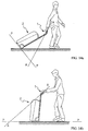
- Figures 14a and 14b illustrate different modes of use of the handle system according to the invention;
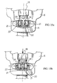
- Figures 15a and 15b are two photograms which illustrate operation of the handle system.
-
- With reference to Figure 1, a handle system according to the invention is denoted in its entirety by 1. Said system 1 is mounted on a
suitcase 2 which has a container body 3 with a set ofrollers 4 mounted on the base of said container body 3 in order to facilitate rolling of thesuitcase 2 along a support surface. - The handle system 1 comprises a
base element 5 connected to said container body 3 as well as anadjustable element 6. Afirst end 6' of saidadjustable element 6 is rotatably connected to saidbase element 5 by an adjusting joint 7 and asecond end 6'' thereof forms ahandle 8. - In accordance with one embodiment, the
handle 8 is formed anatomically so that it can be adapted to the form of the human hand. Advantageously, saidadjustable element 6 has an overall shape which is curved so as to be adapted in the abovementioned locked positions both to the anatomy and to the inclination of the hand of the person who is pushing or pulling thesuitcase 2. - In accordance with a further embodiment, the
suitcase 2, or a trolley, comprises at least one element for locking the opening of the half-shells forming the suitcase. For example, the half-shells arranged next to each other to form the suitcase are kept closed in a releasable manner by means of at least one lock (100) positioned on the facing edges of the latter, in particular along the edges present on the vertical side of the suitcase. Advantageously, the suitcase has at least onelock rollers 4 and, preferably, twolocks - As shown for example in Figures 2 and 5, said adjusting joint comprises a
pin 9 which is rotatably housed in one or more seats formed in acentral lug 10 of saidfirst end 6' of theadjustable element 6 and inserted intoholes 11 provided in twolateral lugs 12 formed bysaid base element 5 so as to create a hinge between saidbase element 5 and saidadjustable element 6. - The
central lug 10 is arranged between thelateral lugs 12, and saidcentral lug 10 andlateral lugs 12 havecontact surfaces 13, 13' which are substantially perpendicular with respect to the orientation of thepin 9 and facing each other. - In order to be able to achieve the abovementioned releasable locking of the
adjustable element 6 with respect to thebase element 5, twokey elements 14 are provided, said elements being inserted with one end intofirst key seats 15 formed in thecontact surfaces 13 of thecentral lug 10 and with the other end into second key seats 15' formed in the contact surfaces 13' of thelateral lugs 12, resulting in a form fit between saidbase element 5 and saidadjustable element 6. - In accordance with the preferred embodiment of the present invention, the
key elements 14 are arranged aligned with saidpin 9 and have through-holes 16 which are substantially central and which form said seats for thepin 9 and which allow a transverse movement of saidkey elements 14 along saidpin 9. - Advantageously, the
key elements 14 have a substantially tubular shape with radial and/orfrontal protuberances 17 which are distributed at intervals along the external circumference of saidelements 14, and said firstkey seats 15 and second key seats 15' have a shape matching the external shape of thekey elements 14 so as to provide said form fit between thebase element 5 and theadjustable element 6. - With even greater advantage, said first
key seats 15 have a shape matching the wholekey element 14 and said second key seats 15' have a shape matching only saidprotuberances 17. This particular configuration allows sliding of saidkey elements 14 inside said firstkey seats 15 as well as locking of saidadjustable element 6 in different angular positions by means of insertion of saidprotuberances 17 in said second key seats 15'. - Both in order to facilitate sliding of the
key elements 14 and in order to increase the locking effect, theprotuberances 17 projecting from saidkey elements 14 also extend with respect to the orientation of thepin 9 in the radial and longitudinal direction and have a substantially trapezoidal shape viewed in cross section. - In the embodiment shown in Figure 5, the
key elements 14 have fourprotuberances 17 distributed at an angle of 90° with respect to each other, and the second key seats 15' have respectively four cavities with a matching shape and arrangement. This results in the possibility of adjustment of theadjustable element 6 with respect to thebase element 5 in 90° steps. - The
first key seats 15 are connected together inside saidcentral lug 10, forming a single through-seat 15 between saidcontact surfaces 13, inside which saidkey elements 14 can be retracted by means of suitable actuating means in order to free said second key seats 15' and disengage said geometric coupling. - In accordance with the preferred embodiment of the invention, said actuating means comprise an
operating pushbutton 18 connected to alongitudinal transmission bar 19, twotransverse transmission elements 20 connected to thekey elements 14 as well as deviatingmeans longitudinal transmission bar 19 into a mutual transverse movement of saidtransmission elements 20 in order to move the twokey elements 14 inside saidfirst seat 15 towards or away from each other. - As can be seen from the figures, said deviating means consist of
studs 21 which extend from thelongitudinal transmission bar 19 andguide channels 22 formed in saidtransverse transmission elements 20, saidguide channels 22 receiving saidstuds 21 and comprising a section inclined with respect to both the longitudinal and the transverse directions. - The
transverse transmission elements 20 are plates directly formed on the mutually facing sides of saidkey elements 14. - In the embodiment shown in Figure 9, each of the
key elements 14 has, associated with them, two of saidplates 20 which are aligned together with a central space for thepin 9, each of saidplates 20 having aguide channel 22 on two opposite sides, respectively. In this case, the total number ofguide channels 22 associated with each individualkey element 14 is four. - In order to convert the longitudinal movement of the
longitudinal transmission bar 19 into a mutual transverse movement of thekey elements 14, theguide channels 22 of both thetransverse transmission elements 20 have a substantially specular form with respect to the plane of thelongitudinal transmission element 19. In particular, theguide channels 22 have respectively two outer sections which are parallel and staggered with respect to each other as well as an inclined central section. Advantageously, the path of theguide channels 22 is rounded and is substantially in the shape of an S. - Depending on the orientation of the
guide channels 22, thekey elements 14 may be moved away from or towards each other by means of a longitudinal movement, in either direction, of thelongitudinal transmission bar 19. The result is that release of the locking action may be performed either by means of pressing or of pulling of the operatingelement 18. - In the embodiment shown in the figures, the operating
pushbutton 18 can be actuated by means of pressure. - A further embodiment envisages an operating
element 18 comprising both a pressing surface and a cavity for the fingers which allows actuation by means of pulling. - In the exploded view of Figure 5 and from the details shown in Figures 7 and 8 it can be seen that said
longitudinal transmission bar 19 is composed of two individual parts which form a double-T section formed by two flanges 19' facing each other and connected by means of a web 19''. - The plate-
like projections 20 of thekey elements 14 are received by the interstice between said flanges 19' on the mutually facing surfaces of which saidstuds 21 are formed, said studs being in turn received and guided by saidguide channels 22. - The
pin 9, in addition to intersecting thekey elements 14, also intersects saidlongitudinal transmission bar 19 which has, in the zone of intersection with thepin 9, anopening 23 which allows a movement of thelongitudinal transmission bar 19 which is perpendicular with respect to thepin 9. - In the embodiment in which said
longitudinal transmission element 19 is a bar in the form of a double T, theopening 23 is formed in said web 19''. - The surface which delimits the side opposite to the
operating element 18 of saidelongated opening 23 forms astop surface 24 for saidpin 9, preventing the actuating means 18, 19, 20, 21, 22 from coming out of theirhousing 25 inside theadjustable element 6. - In order to prevent accidental unlocking of the
adjustable element 6, twohelical springs 26 which are pre-tensioned and which abut in special counter-seats formed in saidhousing 25 are also envisaged, saidhelical springs 26 acting directly on the operatingelement 18. - Owing to the resilient pre-tensioning of the
helical springs 26, the insertion of theprotuberances 17 into said second key seats 15' becomes a snap-type engagement and release of the locking action by means of retraction of thekey elements 14 requires that the resilient force of thesprings 26 must be overcome by means of manual operation of theactuating element 18. - Obviously, the
abovementioned stop surface 24 prevents the operatingelement 18 from coming out of thehousing 25 owing to the resilient load exerted by thesprings 26. - In accordance with a particularly advantageous embodiment, the
base element 5 is not formed as one piece, but has an extractable portion 5', connected to said adjusting joint 7, and a fixed portion 5'', which can be connected to said container body. The extractable portion 5' is slidably housed inside achannel 27 formed in the fixed portion 5' and allows adjustment of the distance between the adjusting joint 7 and the container body 3. - Advantageously, the
channel 27 has, viewed in cross section, a substantially elliptical shape and the extractable portion 5' has, viewed in cross section, a substantially elliptical tubular shape matching the cross section of thechannel 27. - In accordance with one embodiment, the
base element 5 has yielding locking means which allow said extractable portion 5' to be locked resiliently in one or more positions inside thechannel 27 of said fixed portion 5''. - These yielding locking means preferably comprise one or
more stop cavities 28 formed in the surface of saidchannel 27 and one or more thrustingelements 29 projecting in a yielding manner from the outer surface of said extractable portion 5' and able to snap-engage resiliently into saidstop cavities 28. - Advantageously, the thrusting
elements 29 are twometal spheres 28 housed inside a small tube with two openings having a diameter smaller than the diameter of the spheres and pushed towards said openings by means of a pre-tensioned spring arranged between said spheres inside the tube, this tube being arranged at the opposite end to the adjusting joint 7 of the extractable portion 5'. - The extractable portion 5' has, formed in it, reinforcing ribs which form a central circular tube for strengthening the walls of the elliptical profile.
- The operating principle of the handle system 1 according to the invention will be described below with reference to the example of a rolling suitcase with four rollers.
- According to a first mode of use involving pulling of a rolling
suitcase 2, the system 1 allows extraction of the extractable portion 5' from thechannel 27 of the fixed portion 5'' by means of thehandle 8 in order to adapt thehandle 8 to the height of the person transporting thesuitcase 2. - During this extraction of the extractable portion 5', the latter slides inside the
channel 27 and is resiliently stopped by means of the thrustingelements 29 which snap-engage inside the stop cavities 28. - During a following step, the
suitcase 2 is brought into an inclined position where it rests with only tworollers 4 on the support surface. Adjustment of the inclination of theadjustable element 6 occurs in three steps: unlocking - adjustment - locking. - Unlocking is performed without difficulty by means of pushing or pulling of the operating
element 18 using the same hand which grips thehandle 8, the longitudinal movement of the operatingelement 18 being transmitted by means of thelongitudinal transmission bar 19. Thestuds 21 of thelongitudinal transmission bar 19 slide inside the inclined section of theguide channels 22 and convert said longitudinal movement into a mutual transverse movement of thekey elements 14, which are fully retracted into the firstkey seats 15, freeing the second key seats 15' and thus releasing locking of the adjustable element 6 (compare Figures 15a and 15b). - The adjustment of the
adjustable element 6 is performed using the same hand which grips thehandle 8. A specific rotating action of the hand is not even required because, owing to the gravitational effect, the centre of gravity of thesuitcase 2 tends to lower automatically, advantageously stabilizing thesuitcase 2 and bringing theadjustable element 6 into the most suitable position for the hand. This adjustment is further facilitated thanks to the curved shape of theadjustable element 6 and the anatomical shape of thehandle 8 itself. - Locking of the
adjustable element 6 in the optimum position for the person transporting the suitcase is performed by means of reinsertion of theprotuberances 17 in the second key seats 15'. Owing to the pre-tensioning of thesprings 26, this reinsertion is performed automatically and by means of snap-engagement, as soon as theprotuberances 17 and the second key seats 15' are aligned with each other again. - In order to prevent automatic locking in an undesirable position, it is sufficient to keep the operating
pushbutton 18 pressed until the adjustable element is located in the locked position desired. - With particular reference to a rolling suitcase which is being pulled along, the angular adjustment of the adjustable element, and therefore of the handle, allows the centre of gravity of the suitcase to be lowered in an advantageous manner and the end section of the handle to be oriented substantially in the vertical direction, as shown for example in Figure 14a.
- According to a second mode of use where the rolling
suitcase 2 is pushed, the system 1, by means of the angular adjustment and linear extraction operations described above, allows thesuitcase 2 to be kept in a vertical position, resting on all four rollers. This position allows the suitcase to be moved as close as possible to the person transporting it and to be manoeuvred in very confined spaces, such as lifts and the like. - By means of adjustment of the
adjustable element 6, thehandle 8 is positioned at a point with respect to thesuitcase 2, which allows the case to be pushed without the risk of overturning it and moreover ensures a certain freedom of movement for the legs of the person transporting it, as can be seen from Figure 14b. - The
key elements 14 as well as the second key seats 15' are formed and positioned in such a way as to ensure a locked condition of theadjustable element 6, which has proved to be unusually advantageous in terms of stability, safety and ease of use. This condition envisages that, in the locked positions of theadjustable element 6, a straight line A which connects the centre of thehandle 8 and the centre of the adjusting joint 7 intersects a plane p defined by the base of thesuitcase 2, outside of the overall volume of therollers 4. - The handle system according to the invention offers numerous advantages.
- In addition to being able to be adapted always to the height of the person transporting the suitcase, the system 1 advantageously allows the centre of gravity of the suitcase to be lowered without changing the distance between person and suitcase.
- The system 1 also allows the suitcase to be pulled along and pushed in very stable, safe and easy conditions. The handle system 1 also allows the suitcase to be pushed in very confined spaces, for example lifts, train and underground railway carriages, in such a way that the suitcase always remains in the immediate vicinity and eyesight of the person, does not cause an obstacle and in any case leaves room for the person's knees. The curved shape of the adjustable element also ensures a substantially vertical orientation of the handle, both during pulling and pushing of the suitcase.
- The arrangement of the
actuating pushbutton 8 allows easy adjustment using the same hand which grips thehandle 8, and, as a result of the abovementioned locking and actuating mechanism, the handle system is unusually versatile and reliable. - Moreover, the tubular and elliptical cross-sectional shape of the extractable portion 5' and the
channel 27 ensures an enormous degree of lateral and torsional rigidity which notably improves the lateral stability, the dynamic behaviour and the control over the direction of the rolling suitcase with respect to the systems of the known art. - Obviously, a person skilled in the art, in order to satisfy contingent and specific requirements, may make further modifications and variations to the handle system 1 for rolling suitcases according to the present invention whereby the scope of protection of the invention is defined by the following claims.
Claims (39)
- Suitcase (2) comprising a container body (3), rolling means (4) for facilitating rolling of said container body (3) along a support surface and a handle system, said handle system comprising:said adjusting joint (7) comprising a central lug (10) formed by said first end (6') of said adjustable element, two lateral lugs (12) formed by said base element (5), said central lug (10) being arranged between said lateral lugs (12) and hinged thereto by a pin (9) inserted into holes (16) provided in the two lateral lugs (12) and in a seat of said central lug (10), said central lug (10) and lateral lugs (12) having contact surfaces (13,13') which are substantially perpendicular with respect to the orientation of the pin (9) and facing each other,a base element (5) connected to said container body (3),an adjustable element (6) having a first end (6') rotatably connected to said base element (5) by an adjusting joint (7) and a second end (6") forming a handle (8),releasable locking means (14,15,15') in said adjusting joint (7) locking said adjustable element (6) in one or more locking positions with respect to said base element (5),actuating means (18,19,20,21,22) in said adjusting joint (7) for releasing said releasable locking means (14,15,15'),
characterised in that said releasable locking means (14, 15, 15') comprise two or more key elements (14) which are inserted respectively with one end into first key seats (15) formed in the contact surface (13) of said central lug (10) and with the other end into second key seats (15') formed in the contact surfaces (13') of said lateral lugs (12), said key elements (14) being retractable into at least one of said first key seats (15) or second key seats (15') by means of said actuating means (18,19,20,21,22) disengaging respectively the other key seat (15,15'). - Suitcase (2) according to Claim 1, in which said actuating means (18,19,20,21,22) comprise an operating element (18) connected to a longitudinal transmission element (19), one or more transverse transmission elements (20) connected to said key elements (14), as well as deviating means (21,22) able to convert a longitudinal movement of said longitudinal transmission element (19) into a mutual transverse movement of said transverse transmission elements (20).
- Suitcase (2) according to Claim 2, in which said longitudinal transmission element (19) comprises one or more rigid bars (19).
- Suitcase (2) according to Claim 3, in which said deviating means (21, 22) comprise one or more studs (21) which extend respectively from one of said transverse transmission elements (20) or longitudinal transmission element (19) and guide channels (22) formed respectively in the other of said transverse transmission elements (20) or longitudinal transmission element (19), said guide channels (22) receiving said studs (21) and comprising a section inclined with respect to both the longitudinal and the transverse direction.
- Suitcase (2) according to Claim 4, in which said transverse transmission elements (20) comprise plate-like projections (20) delimiting said guide channels (22) and formed directly at the mutually facing ends of said key elements (14).
- Suitcase (2) according to Claim 5, in which said longitudinal transmission elements (19) comprise a bar with a cross-sectional shape in the form of a double T formed by two flanges (19') facing each other and connected by means of a web (19''), said plate-like projections (20) of the key elements (14) being received by the interstice between said flanges (19') on the mutually facing surfaces of which said studs (21) are formed, said studs being received and guided by said guide channels (22) of said plate-like projections (20).
- Suitcase (2) according to any one of the preceding claims 2 to 6, comprising spring means (26) acting on said actuating means (18, 19, 20, 21, 22) so as to prevent accidental unlocking of the adjustable element (6).
- Suitcase (2) according to Claim 7, in which said actuating means (18, 19, 20, 21, 22) and said spring means (26) are arranged inside a housing (25) formed in said adjustable element (6).
- Suitcase (2) according to Claim 8, in which said spring means (26) comprise one or more pre-tensioned helical springs (26) abutting in a special counter-seat formed in said housing (25) and acting directly on the operating element (18).
- Suitcase (2) according to any one of the preceding claims 2 to 9, in which said actuating means (18, 19, 20, 21, 22) comprise stop means (9, 24) for preventing said operating element (18) from coming out of said housing (25) owing to the resilient load exerted by said spring means (26).
- Suitcase (2) according to any one of the preceding claims 2 to 10, in which said key elements (14) are arranged aligned with said pin (9) and have substantially central through-holes (16) which form seats for the pin (9) and allow a transverse movement of said key elements (14) along said pin (9).
- Suitcase (2) according to Claim 11, in which said pin (9) also intersects said longitudinal transmission element (19) which has, in the zone of intersection with the pin (9), an opening (23) which allows a movement of said longitudinal transmission element (19) which is perpendicular with respect to said pin (9).
- Suitcase (2) according to Claim 12, in which said opening (23) is formed in said web (19'').
- Suitcase (2) according to one of Claims 12 or 13, in which one of the surfaces delimiting said opening (23) forms a stop surface (24) for said pin (9), which prevents said actuating means (18, 19, 20, 21, 22) from coming out of said housing (25).
- Suitcase (2) according to any one of the preceding claims 7 to 14, in which the release of said releasable locking means (14, 15, 15') is performed by means of manual actuation of said operating element (18) opposing the resilient force of said spring means (26).
- Suitcase (2) according to any one of the preceding claims, in which said key elements (14) have a substantially tubular shape with radial and/or frontal protuberances (17) and said first key seats (15) and second key seats (15') have a matching shape for receiving said protuberances (17), providing a form fit.
- Suitcase (2) according to Claim 16, in which said protuberances (17) are distributed at intervals along the external circumference of said key elements (14).
- Suitcase (2) according to Claim 16, in which said first key seats (15) have a shape matching the whole key element (14) and said second key seats (15') have a shape matching only said protuberances (17), allowing the sliding of said key elements (14) inside said first seats (15) as well as locking of said adjustable element (6) in different angular positions by means of insertion of said protuberances (17) in said second seats (15').
- Suitcase (2) according to Claim 18, in which, owing to the resilient pre-tensioning of spring means (26), the insertion of said protuberances (17) in said second seats (15') is of the snap-engagement type.
- Suitcase (2) according to Claim 18 or 19, in which said protuberances (17) of said key elements (14) extend in the radial and longitudinal direction of the pin (9) and have a substantially trapezoidal-shaped cross section.
- Suitcase (2) according to any one of Claims 18 to 20, in which said protuberances (17) are four in number.
- Suitcase (2) according to any one of the preceding claims 4 to 21, in which said guide channels (22) associated with each of said key elements (14) are four in number.
- Suitcase (2) according to any one of the preceding claims 4 to 22, in which said guide channels (22) extend along a substantially S-shaped path.
- Suitcase (2) according to any one of the preceding claims 2 to 23, in which said operating element (18) is a pushbutton (18) which can be actuated by means of pressure.
- Suitcase (2) according to any one of the preceding claims, in which said adjustable element (6) has an overall shape which is curved and an anatomical handle (8) able to be adapted in said locked positions to the anatomy and to the inclination of the human hand.
- Suitcase (2) according to any one of the preceding claims, in which said base element (5) has an extractable portion (5') connected to said adjusting joint (7) and a fixed portion (5'') which can be connected to said container body (3).
- Suitcase (2) according to Claim 26, in which said extractable portion (5') is slidably housed in a channel (27) formed inside said fixed portion (5''), allowing the adjustment of the distance between said adjusting joint (7) and said container body (3).
- Suitcase (2) according to Claim 27, comprising yielding locking means (28, 29) able to lock resiliently said extractable element (5') in one or more positions inside said fixed element (5').
- Suitcase (2) according to Claim 28, in which said yielding locking means (28, 29) comprise one or more stop cavities (28) formed in the surface of said channel (27) and one or more thrusting elements (29) projecting in a yielding manner from the outer surface of said extractable portion (5') and able to snap-engage resiliently into said stop cavities (28).
- Suitcase (2) according to Claim 29, in which said thrusting elements (29) comprise spheres (28) resiliently pre-tensioned by springs.
- Suitcase (2) according to Claim 27, in which said channel (27) has a substantially elliptical shape viewed in cross section.
- Suitcase (2) according to Claim 31, in which said extractable portion (5') has a substantially elliptical tubular shape viewed in cross section, matching the cross section of said channel (27).
- Suitcase (2) according to Claim 32, in which said extractable portion (5') has reinforcing ribs.
- Suitcase (2) according to Claim 33, in which said reinforcing ribs form a central circular tube able to strengthen the walls of said elliptical section.
- Suitcase (2) according to any of the preceding claims, in which the angle of inclination of said handle (8) with respect to said container body (3) is adjustable by means of said adjusting joint (7).
- Suitcase (2) according to Claim 35, in which the distance between said handle (8) and said container body (3) is adjustable by means of said adjusting joint (7).
- Suitcase (2) according to Claim 36, in which the distance between said adjusting joint (7) and said container body (3) is adjustable by means of said base element (5).
- Suitcase (2) according to any one of the preceding Claims, in which said rolling elements (4) are arranged on a base of the suitcase (2) and in which, in the locked positions of said adjustable element (6), a straight line A which connects the centre of the handle (8) and the centre of the adjusting joint (7) intersects a plane (p) defined by said base outside of the overall volume of said rolling means (4).
- Suitcase (2), according to any one of the preceding claims, comprising at least one lock (101; 102) in the side of said suitcase opposite to rolling means (4), able to close in a releasable manner two half-shells forming the body of the suitcase.
Priority Applications (5)
| Application Number | Priority Date | Filing Date | Title |
|---|---|---|---|
| ES01830638T ES2223768T3 (en) | 2001-10-09 | 2001-10-09 | HANDLE SYSTEM FOR ROLLING SUITCASES. |
| AT01830638T ATE272958T1 (en) | 2001-10-09 | 2001-10-09 | ROLLER SUITCASE WITH HANDLE SYSTEM |
| EP01830638A EP1302123B1 (en) | 2001-10-09 | 2001-10-09 | Rolling suitcase with handle system |
| DE60104856T DE60104856T2 (en) | 2001-10-09 | 2001-10-09 | Trolley with handle system |
| PCT/EP2002/008911 WO2003030674A1 (en) | 2001-10-09 | 2002-08-09 | Handle system for rolling suitcases |
Applications Claiming Priority (1)
| Application Number | Priority Date | Filing Date | Title |
|---|---|---|---|
| EP01830638A EP1302123B1 (en) | 2001-10-09 | 2001-10-09 | Rolling suitcase with handle system |
Publications (2)
| Publication Number | Publication Date |
|---|---|
| EP1302123A1 EP1302123A1 (en) | 2003-04-16 |
| EP1302123B1 true EP1302123B1 (en) | 2004-08-11 |
Family
ID=8184728
Family Applications (1)
| Application Number | Title | Priority Date | Filing Date |
|---|---|---|---|
| EP01830638A Expired - Lifetime EP1302123B1 (en) | 2001-10-09 | 2001-10-09 | Rolling suitcase with handle system |
Country Status (5)
| Country | Link |
|---|---|
| EP (1) | EP1302123B1 (en) |
| AT (1) | ATE272958T1 (en) |
| DE (1) | DE60104856T2 (en) |
| ES (1) | ES2223768T3 (en) |
| WO (1) | WO2003030674A1 (en) |
Families Citing this family (4)
| Publication number | Priority date | Publication date | Assignee | Title |
|---|---|---|---|---|
| FR2896670B1 (en) * | 2006-02-01 | 2008-07-04 | Louis Vuitton Malletier Sa | TOWABLE HANDBAG EQUIPPED WITH A TELESCOPIC ROD |
| CN105901875B (en) * | 2016-05-25 | 2018-07-03 | 邵东县聚德箱包有限公司 | A kind of trolley case |
| CN108283352A (en) * | 2016-05-25 | 2018-07-17 | 刘小红 | A kind of standoff trolley case of band |
| CN106037199B (en) * | 2016-05-25 | 2018-01-30 | 卢前程 | A new type of trolley case with tipping protection function |
Family Cites Families (5)
| Publication number | Priority date | Publication date | Assignee | Title |
|---|---|---|---|---|
| DE9302510U1 (en) * | 1993-02-20 | 1994-05-05 | Sudhaus Schloß- und Beschlagtechnik GmbH + Co, 58644 Iserlohn | Handle for roller case |
| US5706921A (en) * | 1996-08-12 | 1998-01-13 | Wang; Jin-Jiao | Retractable handle assembly for a suitcase |
| US5901822A (en) * | 1997-11-05 | 1999-05-11 | Tu; A-Shih | Retractable travel bag pulling handle |
| US6301746B1 (en) * | 1998-01-09 | 2001-10-16 | Andiamo, Inc. | Telescoping handle assembly for luggage and other luggable items |
| US6220477B1 (en) * | 1999-12-02 | 2001-04-24 | Mark H. Schneider | Flip-handle cookware |
-
2001
- 2001-10-09 AT AT01830638T patent/ATE272958T1/en not_active IP Right Cessation
- 2001-10-09 EP EP01830638A patent/EP1302123B1/en not_active Expired - Lifetime
- 2001-10-09 DE DE60104856T patent/DE60104856T2/en not_active Expired - Fee Related
- 2001-10-09 ES ES01830638T patent/ES2223768T3/en not_active Expired - Lifetime
-
2002
- 2002-08-09 WO PCT/EP2002/008911 patent/WO2003030674A1/en not_active Ceased
Also Published As
| Publication number | Publication date |
|---|---|
| WO2003030674A1 (en) | 2003-04-17 |
| ES2223768T3 (en) | 2005-03-01 |
| EP1302123A1 (en) | 2003-04-16 |
| DE60104856D1 (en) | 2004-09-16 |
| ATE272958T1 (en) | 2004-08-15 |
| DE60104856T2 (en) | 2005-08-18 |
Similar Documents
| Publication | Publication Date | Title |
|---|---|---|
| US6802409B1 (en) | Wheeled luggage and associated devices | |
| US5568848A (en) | Laterally movable suitcase with wheeled, pivotable leg | |
| CA1327378C (en) | Suitecase frame | |
| US6182981B1 (en) | Two-stage expansion/collapse control mechanism for use on a hand-trailable luggage case | |
| CA2208102C (en) | Roller mechanism for container or cart | |
| US6079941A (en) | Moving system | |
| US6301746B1 (en) | Telescoping handle assembly for luggage and other luggable items | |
| US5630488A (en) | Retractable handle positioning structure for luggage | |
| JPH0625408Y2 (en) | Wheelbarrow height adjustment mechanism for wheelbarrow | |
| US20080230339A1 (en) | Stair wheeler | |
| CN113062682B (en) | Foldable door | |
| EP1059859A1 (en) | Improvements in wheeled luggage and associated devices | |
| US5642552A (en) | Retractable handle positioning mechanism for wheeled suitcases | |
| EP0135666A2 (en) | Convertible fold-up ladder | |
| US20060213735A1 (en) | Wheeled carrier stair sliding system | |
| ITMI950538U1 (en) | HIGH CHAIR WITH PERFECTED RECLINATION MECHANISM | |
| TW201740833A (en) | Operating handle device | |
| EP1302123A1 (en) | Handle system for rolling suitcases | |
| US7798499B2 (en) | Wheeled luggage usable as a seat | |
| WO2015110667A1 (en) | Travel bag | |
| US5588513A (en) | Tilt-locking pull handle for a wheeled suitcase | |
| JP4505453B2 (en) | Selectable rotatable handle assembly for towable tacks | |
| RU2764334C1 (en) | Foldable reversible baby stroller | |
| DE102011000610B4 (en) | Cart for transporting a stacking box | |
| HUE033410T2 (en) | Suitcase |
Legal Events
| Date | Code | Title | Description |
|---|---|---|---|
| PUAI | Public reference made under article 153(3) epc to a published international application that has entered the european phase |
Free format text: ORIGINAL CODE: 0009012 |
|
| AK | Designated contracting states |
Designated state(s): AT BE CH CY DE DK ES FI FR GB GR IE IT LI LU MC NL PT SE TR |
|
| AX | Request for extension of the european patent |
Extension state: AL LT LV MK RO SI |
|
| 17P | Request for examination filed |
Effective date: 20030819 |
|
| 17Q | First examination report despatched |
Effective date: 20031103 |
|
| AKX | Designation fees paid |
Designated state(s): AT BE CH CY DE DK ES FI FR GB GR IE IT LI LU MC NL PT SE TR |
|
| GRAP | Despatch of communication of intention to grant a patent |
Free format text: ORIGINAL CODE: EPIDOSNIGR1 |
|
| RTI1 | Title (correction) |
Free format text: ROLLING SUITCASE WITH HANDLE SYSTEM |
|
| GRAS | Grant fee paid |
Free format text: ORIGINAL CODE: EPIDOSNIGR3 |
|
| GRAA | (expected) grant |
Free format text: ORIGINAL CODE: 0009210 |
|
| AK | Designated contracting states |
Kind code of ref document: B1 Designated state(s): AT BE CH CY DE DK ES FI FR GB GR IE IT LI LU MC NL PT SE TR |
|
| PG25 | Lapsed in a contracting state [announced via postgrant information from national office to epo] |
Ref country code: FI Free format text: LAPSE BECAUSE OF FAILURE TO SUBMIT A TRANSLATION OF THE DESCRIPTION OR TO PAY THE FEE WITHIN THE PRESCRIBED TIME-LIMIT Effective date: 20040811 Ref country code: LI Free format text: LAPSE BECAUSE OF FAILURE TO SUBMIT A TRANSLATION OF THE DESCRIPTION OR TO PAY THE FEE WITHIN THE PRESCRIBED TIME-LIMIT Effective date: 20040811 Ref country code: CY Free format text: LAPSE BECAUSE OF FAILURE TO SUBMIT A TRANSLATION OF THE DESCRIPTION OR TO PAY THE FEE WITHIN THE PRESCRIBED TIME-LIMIT Effective date: 20040811 Ref country code: AT Free format text: LAPSE BECAUSE OF FAILURE TO SUBMIT A TRANSLATION OF THE DESCRIPTION OR TO PAY THE FEE WITHIN THE PRESCRIBED TIME-LIMIT Effective date: 20040811 Ref country code: CH Free format text: LAPSE BECAUSE OF FAILURE TO SUBMIT A TRANSLATION OF THE DESCRIPTION OR TO PAY THE FEE WITHIN THE PRESCRIBED TIME-LIMIT Effective date: 20040811 Ref country code: NL Free format text: LAPSE BECAUSE OF FAILURE TO SUBMIT A TRANSLATION OF THE DESCRIPTION OR TO PAY THE FEE WITHIN THE PRESCRIBED TIME-LIMIT Effective date: 20040811 Ref country code: TR Free format text: LAPSE BECAUSE OF FAILURE TO SUBMIT A TRANSLATION OF THE DESCRIPTION OR TO PAY THE FEE WITHIN THE PRESCRIBED TIME-LIMIT Effective date: 20040811 |
|
| REG | Reference to a national code |
Ref country code: GB Ref legal event code: FG4D |
|
| REG | Reference to a national code |
Ref country code: CH Ref legal event code: EP |
|
| REG | Reference to a national code |
Ref country code: IE Ref legal event code: FG4D |
|
| REF | Corresponds to: |
Ref document number: 60104856 Country of ref document: DE Date of ref document: 20040916 Kind code of ref document: P |
|
| PG25 | Lapsed in a contracting state [announced via postgrant information from national office to epo] |
Ref country code: LU Free format text: LAPSE BECAUSE OF NON-PAYMENT OF DUE FEES Effective date: 20041009 |
|
| PG25 | Lapsed in a contracting state [announced via postgrant information from national office to epo] |
Ref country code: IE Free format text: LAPSE BECAUSE OF NON-PAYMENT OF DUE FEES Effective date: 20041011 |
|
| PG25 | Lapsed in a contracting state [announced via postgrant information from national office to epo] |
Ref country code: MC Free format text: LAPSE BECAUSE OF NON-PAYMENT OF DUE FEES Effective date: 20041031 |
|
| PG25 | Lapsed in a contracting state [announced via postgrant information from national office to epo] |
Ref country code: SE Free format text: LAPSE BECAUSE OF FAILURE TO SUBMIT A TRANSLATION OF THE DESCRIPTION OR TO PAY THE FEE WITHIN THE PRESCRIBED TIME-LIMIT Effective date: 20041111 Ref country code: GR Free format text: LAPSE BECAUSE OF FAILURE TO SUBMIT A TRANSLATION OF THE DESCRIPTION OR TO PAY THE FEE WITHIN THE PRESCRIBED TIME-LIMIT Effective date: 20041111 Ref country code: DK Free format text: LAPSE BECAUSE OF FAILURE TO SUBMIT A TRANSLATION OF THE DESCRIPTION OR TO PAY THE FEE WITHIN THE PRESCRIBED TIME-LIMIT Effective date: 20041111 |
|
| ET | Fr: translation filed | ||
| NLV1 | Nl: lapsed or annulled due to failure to fulfill the requirements of art. 29p and 29m of the patents act | ||
| REG | Reference to a national code |
Ref country code: CH Ref legal event code: PL |
|
| REG | Reference to a national code |
Ref country code: ES Ref legal event code: FG2A Ref document number: 2223768 Country of ref document: ES Kind code of ref document: T3 |
|
| PLBE | No opposition filed within time limit |
Free format text: ORIGINAL CODE: 0009261 |
|
| STAA | Information on the status of an ep patent application or granted ep patent |
Free format text: STATUS: NO OPPOSITION FILED WITHIN TIME LIMIT |
|
| REG | Reference to a national code |
Ref country code: IE Ref legal event code: MM4A |
|
| 26N | No opposition filed |
Effective date: 20050512 |
|
| PGFP | Annual fee paid to national office [announced via postgrant information from national office to epo] |
Ref country code: GB Payment date: 20061016 Year of fee payment: 6 |
|
| PGFP | Annual fee paid to national office [announced via postgrant information from national office to epo] |
Ref country code: DE Payment date: 20061025 Year of fee payment: 6 |
|
| PGFP | Annual fee paid to national office [announced via postgrant information from national office to epo] |
Ref country code: BE Payment date: 20061108 Year of fee payment: 6 |
|
| PG25 | Lapsed in a contracting state [announced via postgrant information from national office to epo] |
Ref country code: PT Free format text: LAPSE BECAUSE OF NON-PAYMENT OF DUE FEES Effective date: 20050111 |
|
| PGFP | Annual fee paid to national office [announced via postgrant information from national office to epo] |
Ref country code: ES Payment date: 20071120 Year of fee payment: 7 |
|
| BERE | Be: lapsed |
Owner name: *VALIGERIA RONCATO S.P.A. Effective date: 20071031 |
|
| GBPC | Gb: european patent ceased through non-payment of renewal fee |
Effective date: 20071009 |
|
| PG25 | Lapsed in a contracting state [announced via postgrant information from national office to epo] |
Ref country code: DE Free format text: LAPSE BECAUSE OF NON-PAYMENT OF DUE FEES Effective date: 20080501 |
|
| PG25 | Lapsed in a contracting state [announced via postgrant information from national office to epo] |
Ref country code: BE Free format text: LAPSE BECAUSE OF NON-PAYMENT OF DUE FEES Effective date: 20071031 |
|
| REG | Reference to a national code |
Ref country code: FR Ref legal event code: ST Effective date: 20080630 |
|
| PGFP | Annual fee paid to national office [announced via postgrant information from national office to epo] |
Ref country code: FR Payment date: 20061002 Year of fee payment: 6 |
|
| PG25 | Lapsed in a contracting state [announced via postgrant information from national office to epo] |
Ref country code: GB Free format text: LAPSE BECAUSE OF NON-PAYMENT OF DUE FEES Effective date: 20071009 |
|
| PGFP | Annual fee paid to national office [announced via postgrant information from national office to epo] |
Ref country code: IT Payment date: 20081014 Year of fee payment: 8 |
|
| PG25 | Lapsed in a contracting state [announced via postgrant information from national office to epo] |
Ref country code: FR Free format text: LAPSE BECAUSE OF NON-PAYMENT OF DUE FEES Effective date: 20071031 |
|
| REG | Reference to a national code |
Ref country code: ES Ref legal event code: FD2A Effective date: 20081010 |
|
| PG25 | Lapsed in a contracting state [announced via postgrant information from national office to epo] |
Ref country code: ES Free format text: LAPSE BECAUSE OF NON-PAYMENT OF DUE FEES Effective date: 20081010 |
|
| PG25 | Lapsed in a contracting state [announced via postgrant information from national office to epo] |
Ref country code: IT Free format text: LAPSE BECAUSE OF NON-PAYMENT OF DUE FEES Effective date: 20091009 |