EP1302117A1 - Device for measuring filling factor of filler for forming rod - Google Patents
Device for measuring filling factor of filler for forming rod Download PDFInfo
- Publication number
- EP1302117A1 EP1302117A1 EP01949926A EP01949926A EP1302117A1 EP 1302117 A1 EP1302117 A1 EP 1302117A1 EP 01949926 A EP01949926 A EP 01949926A EP 01949926 A EP01949926 A EP 01949926A EP 1302117 A1 EP1302117 A1 EP 1302117A1
- Authority
- EP
- European Patent Office
- Prior art keywords
- rod
- light
- shaped article
- tobacco
- light sources
- Prior art date
- Legal status (The legal status is an assumption and is not a legal conclusion. Google has not performed a legal analysis and makes no representation as to the accuracy of the status listed.)
- Granted
Links
Images

Classifications
-
- A—HUMAN NECESSITIES
- A24—TOBACCO; CIGARS; CIGARETTES; SIMULATED SMOKING DEVICES; SMOKERS' REQUISITES
- A24C—MACHINES FOR MAKING CIGARS OR CIGARETTES
- A24C5/00—Making cigarettes; Making tipping materials for, or attaching filters or mouthpieces to, cigars or cigarettes
- A24C5/32—Separating, ordering, counting or examining cigarettes; Regulating the feeding of tobacco according to rod or cigarette condition
- A24C5/34—Examining cigarettes or the rod, e.g. for regulating the feeding of tobacco; Removing defective cigarettes
- A24C5/3412—Examining cigarettes or the rod, e.g. for regulating the feeding of tobacco; Removing defective cigarettes by means of light, radiation or electrostatic fields
-
- G—PHYSICS
- G01—MEASURING; TESTING
- G01N—INVESTIGATING OR ANALYSING MATERIALS BY DETERMINING THEIR CHEMICAL OR PHYSICAL PROPERTIES
- G01N9/00—Investigating density or specific gravity of materials; Analysing materials by determining density or specific gravity
- G01N9/24—Investigating density or specific gravity of materials; Analysing materials by determining density or specific gravity by observing the transmission of wave or particle radiation through the material
-
- Y—GENERAL TAGGING OF NEW TECHNOLOGICAL DEVELOPMENTS; GENERAL TAGGING OF CROSS-SECTIONAL TECHNOLOGIES SPANNING OVER SEVERAL SECTIONS OF THE IPC; TECHNICAL SUBJECTS COVERED BY FORMER USPC CROSS-REFERENCE ART COLLECTIONS [XRACs] AND DIGESTS
- Y10—TECHNICAL SUBJECTS COVERED BY FORMER USPC
- Y10S—TECHNICAL SUBJECTS COVERED BY FORMER USPC CROSS-REFERENCE ART COLLECTIONS [XRACs] AND DIGESTS
- Y10S131/00—Tobacco
- Y10S131/905—Radiation source for sensing condition or characteristic
-
- Y—GENERAL TAGGING OF NEW TECHNOLOGICAL DEVELOPMENTS; GENERAL TAGGING OF CROSS-SECTIONAL TECHNOLOGIES SPANNING OVER SEVERAL SECTIONS OF THE IPC; TECHNICAL SUBJECTS COVERED BY FORMER USPC CROSS-REFERENCE ART COLLECTIONS [XRACs] AND DIGESTS
- Y10—TECHNICAL SUBJECTS COVERED BY FORMER USPC
- Y10S—TECHNICAL SUBJECTS COVERED BY FORMER USPC CROSS-REFERENCE ART COLLECTIONS [XRACs] AND DIGESTS
- Y10S131/00—Tobacco
- Y10S131/906—Sensing condition or characteristic of continuous tobacco rod
Definitions
- the present invention relates to a device for detecting a filling density of filler in a rod-shaped article and, more specifically, to a detecting device suitable for detecting a shred tobacco filling density in a tobacco rod produced by a cigarette manufacturing machine.
- This kind of filling density detecting device conventionally uses radial rays. More specifically, the detecting device emits radial rays toward a tobacco rod, and detects the filling density of shredded tobacco, based on the degree of attenuation of the radial rays passing through the shredded tobacco.
- radial rays require a strict control system as a safety measure, and it is not easy to handle the radial ray-type detecting device.
- This known detecting device comprises a plurality of infrared light sources and a plurality of light receivers.
- the light sources and the light receivers are disposed along a horizontal delivery path for a tobacco rod in a cigarette manufacturing machine.
- the delivery path extends from a wrapping section of the cigarette manufacturing machine.
- infrared rays are irradiated from each light source toward the outer peripheral surface of tobacco rod, and the infrared rays which have been transmitted through the tobacco rod or diffused in gaps in the tobacco rod are received by each light receiver. Then, based on the quantity of the received infrared rays, a density signal indicative of the shredded tobacco filling density is output.
- the output level of the density signal is higher in a diffusion type in which infrared rays are diffused than a transmission type in which infrared rays are transmitted, and a detecting device of the diffusion type is suitable for measuring the shredded tobacco filling density. Therefore, the filling density of the shredded tobacco in the tobacco rod may be measured by using the diffusion type detecting device, and in this case soft spots in the tobacco rod can also be detected.
- the soft spot here means a part of the tobacco rod having a shredded tobacco filling density lower than a reference range.
- the infrared light sources and the light receivers are alternately disposed in the circumferential direction of the tobacco rod. Moreover, each light source and each light receiver are disposed so as to face another light source and another light receiver, respectively, across the tobacco rod.
- the known detecting device is low in diffusion efficiency of infrared rays in the tobacco rod, and thus is not capable of detecting the shredded tobacco filling density with high accuracy throughout the whole cross-sectional area of the tobacco rod.
- the known detecting device is not capable of satisfactorily diffusing infrared rays in the tobacco rod, showing low soft-spot detection accuracy.
- An object of the present invention is to provide a detecting device capable of detecting with high accuracy a filling density of filler in a rod-shaped article by using inspection light except radial rays, which can be controlled easily.
- a detecting device of the present invention comprising light incidence means for making inspection light incident into a rod-shaped article, light-receiving means for receiving the inspection light from the rod-shaped article, and measuring means for measuring a filling density of filler based on an output from the light-receiving means.
- the light incidence means has a plurality of light sources disposed in a predetermined arcuate area surrounding the rod-shaped article adjacently to each other in a circumferential direction of the rod-shaped article and causing the inspection light to enter the rod-shaped article in an identical cross section of the rod-shaped article.
- the light receiving means has at least one light receiver disposed in an area other than the arcuate area in the circumferential direction of the rod-shaped article so as not to face any of the light sources, receiving the inspection light emitted from the rod-shaped article along the cross section, and generating a signal indicative of the received-light quantity.
- the inspection light incident from each light source into the rod-shaped article is reflected by the filler in the rod-shaped article, and as the reflection is repeated, the inspection light is diffused in gaps in the rod-shaped article. Then, the diffused inspection light is emitted from the rod-shaped article and received by the light receiver.
- the light receiver supplies a signal corresponding to the quantity of the received inspection light to the measuring means, which measures the filling density of the filler based on the received signal.
- the quantity of the diffused inspection light received by the light receiver represents an accurate density of the filler in the rod-shaped article.
- the light incidence means may include four light sources arranged separately from one another at a predetermined angle in the circumferential direction of the rod-shaped article.
- the light receiving means may include two light receivers which are also arranged separately from each other at a predetermined angle in the circumferential direction of the rod-shaped article.
- the detecting device measures a shredded tobacco filling density in the tobacco rod.
- each light source of the detecting device causes the inspection light to enter the tobacco rod in a direction other than the horizontal direction.
- the inspection light never passes through gaps of the shredded tobacco in the tobacco rod without being reflected, so that only the diffused inspection light is emitted from the tobacco rod.
- the four light sources are arranged separately from one another at an angle of 45°, while the two light receivers are arranged separately from each other at an angle of 90°. More preferably, two of the light sources are disposed adjacently to each other with a vertical longitudinal section of the rod-shaped article therebetween, and the remaining two light sources are disposed adjacently to each other with a horizontal longitudinal section of the rod-shaped article therebetween. With this arrangement, the inspection light from the light sources is diffused uniformly in the tobacco rod, which enables the light receivers to satisfactorily receive the inspection light emitted from the tobacco rod.
- one of the light receivers may be disposed on the vertical longitudinal section, and the other may be disposed on the horizontal longitudinal section.
- the light sources and the light receivers may be mounted on a holder surrounding the tobacco rod, and the light sources and the light receivers in this instance form one detecting unit.
- Each light source is capable of making infrared rays as the inspection light incident into the tobacco rod. Infrared rays are excellent in diffusibility within the tobacco rod and can be easily controlled.
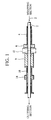
- Fig. 1 shows a part of a cigarette manufacturing machine, namely, a horizontal delivery path 2 for a tobacco rod T, the delivery path 2 extending from a wrapping section and through a cutting section of the machine.
- the wrapping section wraps in paper a tobacco stream in which shredded tobacco is vertically layered, to form the tobacco rod T.
- the shredded tobacco in the tobacco rod T substantially maintains its vertically layered state.
- the cutting section of the machine cuts the tobacco rod T into a predetermined length to form cigarette rods, which have a length equivalent to two cigarettes used in the manufacture of filter cigarettes.
- the delivery path 2 includes rod guides 4, 6, 8 and 10 allowing the tobacco rod T to pass therethrough, and each rod guide is in the shape of a tube or a ring.
- the rod guides 4, 6, 8 and 10 are sequentially disposed in a delivery direction of the tobacco rod T.
- the rod guide 10 on the cutting section side is in the shape of a tube, and a detecting unit 14 of a diffusion type according to an embodiment of the invention is disposed in the middle of the rod guide 10.
- the detecting unit 12 is used to evaluate output results of the detecting unit 14.
- Fig. 2 illustrates details of the detecting unit 14, which comprises a ring-shaped holder 16 surrounding an outer periphery of the rod guide 10.
- the holder 16 comprises four light sources 18, 20, 22 and 24, and two light receivers 26 and 28.
- Each light source is a halogen lamp that emits infrared rays, whereas each light receiver is a photoelectric converter.
- the four light sources and the two light receivers are located on a same cross section of the holder 16. More specifically, the light sources 18, 20, 22, and 24 are arranged at intervals in a circumferential direction of the holder 16 and have infrared-ray emitting portions 18a, 20a, 22a and 24a projecting into the rod guide 10. The emitting portions are separately arranged at an angle of 45° in the circumferential direction of the tobacco rod T passing through the rod guide 10.
- the rod guide 10 is provided with radial holes 30, 32, 34 and 36, which are also separately arranged at an angle of 45° in the circumferential direction of the rod guide 10 and receive the emitting portions of their corresponding light sources 18, 20, 22 and 24.
- the radial holes 30, 32, 34 and 36 open in an inner peripheral surface of the rod guide 10, allowing the infrared rays from the light sources 18, 20, 22 and 24 to be irradiated on an outer peripheral surface of the tobacco rod T through their respective radial holes.
- the light sources 18 and 20 are arranged apart from each other with a vertical longitudinal section P V of the holder 16 therebetween, whereas the light sources 22 and 24 are arranged apart from each other with a horizontal longitudinal section P H of the holder 16 therebetween. Accordingly, the infrared-ray emitting direction of each light source intersects the layering direction of the shredded tobacco in the tobacco rod T.
- the light receivers 26 and 28 are disposed in an area opposite to the light sources 18, 20, 22 and 24, as viewed in a diametrical direction of the holder 16. More specifically, the light receivers 26 and 28 are located on the longitudinal sections P V and P H , respectively, and have light-receiving portions 26a and 28a projecting into the rod guide 10.
- the rod guide 10 further has two radial holes 38 and 40 for receiving the light-receiving portions of their corresponding light receivers.
- the radial holes 38 and 40 also open in the inner peripheral surface of the rod guide 10, and thus the light-receiving portions of the light receivers 26 and 28 can receive the infrared rays which have passed through the tobacco rod T.
- a void ratio in the tobacco rod T is in a range from about 65% to 70%.
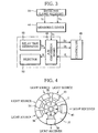
- each of the light sources 18, 20, 22 and 24 is electrically connected to an electric supply circuit 42, while each of the light receivers 26 and 28 is electrically connected to a measuring device 44.
- each light source emits infrared rays through its emitting portion, and the infrared rays are introduced into the tobacco rod T through the respective radial holes 30, 32, 34 and 36.
- the infrared rays thus introduced are diffused into gaps of the shredded tobacco in the tobacco rod T while being reflected by the shredded tobacco, and then emitted from the tobacco rod T through the radial holes 38 and 40 to be received by the light-receiving portions of the light receivers 26 and 28.
- the light receivers 26 and 28 supply electric signals V 1 and V 2 to the measuring device 44, respectively.
- the electric signals V 1 and V 2 are proportional to the respective quantities of the infrared rays received.
- the measuring device 44 Based on the electric signals V 1 and V 2 from the light receivers 26 and 28, the measuring device 44 generates a density signal S D indicative of a shredded tobacco filling density in the tobacco rod T and sends the signal to the cigarette manufacturing machine.
- measuring device 44 a measuring device disclosed in the above-mentioned publication may be used, and therefore a detailed explanation of the measuring device 44 is omitted.
- the density signal S D sent from the measuring device 44 is supplied to a controller 48 via an A/D conversion board 46 of the cigarette manufacturing machine, the controller 48 including a microcomputer. Meanwhile, delay time S T is supplied from a delay time generator 50 of the machine to the controller 48 via the A/D conversion board 46.
- the delay time generator 50 calculates the delay time S T , based on a distance from the detecting unit 14 to a cigarette rod rejecting device 52 arranged on a downstream side of the cutting section and a current delivery speed of the tobacco rod T, namely, the cigarette rods.
- the delay time S T represents the time required for a part of the tobacco rod T which has passed the detecting unit 14 to reach the rejecting device 52 as a cigarette rod.
- the controller 48 On receiving the density signal S D , the controller 48 compares the density signal S D with a reference range. If the density signal S D is smaller than the reference range, that is, if the shredded tobacco filling density is too much lower than a reference filling density, the controller 48 judges that there exists a soft spot in the tobacco rod T, which is lower in the shredded tobacco filling density, and supplies a rejection signal E to the rejecting device 52 via the A/D conversion board 46 after the lapse of the delay time S T from the determination time.
- the rejecting device 52 As soon as the rejecting device 52 receives the rejection signal E, the rejecting device 52 starts immediately and rejects the cigarette rod including the soft spot to outside the delivery path 2.
- the infrared rays from the light sources enter the tobacco rod T from an outer peripheral region spanning about 135°, as viewed in the circumferential direction of the tobacco rod T. Therefore, as is obvious from Fig. 4, the infrared rays incident into the tobacco rod T are directed to the inside of the tobacco rod T so as to cover substantially the whole cross section of the tobacco rod T. The infrared rays introduced into the tobacco rod T are reflected by the shredded tobacco inside the rod, and the reflection is repeated, so that the infrared rays are uniformly diffused in gaps in the tobacco rod T.
- the infrared rays uniformly diffused in the tobacco rod T leak out through the radial holes 38 and 40 of the rod guide 10, and the leaked-out infrared rays are received by the light receivers 26 and 28. Since the infrared rays received by the light receivers 26 and 28 have been uniformly diffused in the tobacco rod T, a received-light level of the infrared rays received by the light receivers 26 and 28 indicates an accurate shredded tobacco filling density, which makes it possible to detect soft spots in the tobacco rod T with high accuracy.
- the infrared rays from the light sources 18, 20, 22 and 24 do not horizontally enter the tobacco rod T, so that the infrared rays do not pass directly through gaps in the tobacco rod T to travel toward the light receivers 26 and 28.
- the light receivers 26 and 28 can receive only the infrared rays which have been diffused in the tobacco rod T, and therefore the received-light quantity of the infrared rays received by the light receivers 26 and 28 represents an accurate shredded tobacco filling density.
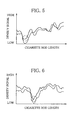
- Figs. 5 to 7 show the results of measurement of the shredded tobacco filling density in the cigarette rod, measured by using the detecting unit 14 of the present invention and the detecting unit 12 of the aforementioned publication at the same time.
- the solid line indicates a waveform of the density signal obtained using the detecting unit 14 of the invention, while the dashed line indicates a waveform of the density signal obtained by using the known detecting unit 12.
- the detecting unit 14 of the present invention shows a generally higher output level of the density signal, permitting higher-accuracy measurement of the filling density.
- dot-and-dash circles indicate the presence of soft spots.
- the present invention is not limited to the above-mentioned embodiment, but may be modified in various ways.
- the number of the light sources and that of the light receivers are not limited to the exemplified ones.
- the detecting device of the present invention may be used not only for detecting soft spots but for measuring an average filling density in the cigarette rod.
- a trimming device for the tobacco stream can be controlled.
- the trimming device is disposed on an upstream side of the wrapping section and adjusts the thickness of the shredded tobacco layer of the tobacco stream.
- the detecting device of the present invention may be used to detect the filling density of other fillers than shredded tobacco.
- the detecting device may be used to detect the filling density of other fillers than shredded tobacco.
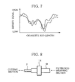
- a filter rod manufacturing machine as illustrated in Fig. 8.
- the filter rod manufacturing machine produces a filter rod F by wrapping a fibrous filter material in paper at its wrapping section, whose structure is similar to that of the wrapping section of the cigarette manufacturing machine.
- the detecting unit 14 is disposed on a rod guide 54 for guiding the filter rod F delivered in a horizontal direction from the wrapping section toward the cutting section, and detects the filling density of the filter material in the filter rod F in the same manner.
Landscapes
- General Health & Medical Sciences (AREA)
- Health & Medical Sciences (AREA)
- Chemical & Material Sciences (AREA)
- Physics & Mathematics (AREA)
- Analytical Chemistry (AREA)
- Biochemistry (AREA)
- Life Sciences & Earth Sciences (AREA)
- General Physics & Mathematics (AREA)
- Immunology (AREA)
- Pathology (AREA)
- Toxicology (AREA)
- Manufacturing Of Cigar And Cigarette Tobacco (AREA)
- Investigating Or Analysing Materials By Optical Means (AREA)
Abstract
Description
Claims (11)
- A device for detecting a filling density of filler forming a rod-shaped article, comprising:light incidence means for causing inspection light to enter the rod-shaped article, said light incidence means including a plurality of light sources disposed in a predetermined arcuate area surrounding the rod-shaped article adjacently to each other in a circumferential direction of the rod-shaped article and causing the inspection light to enter the rod-shaped article in an identical cross section of the rod-shaped article;light-receiving means for receiving the inspection light from the rod-shaped article, said light-receiving means including at least one light receiver disposed in an area other than said arcuate area in the circumferential direction of the rod-shaped article so as not to face any of said light sources, said light receiver receiving the inspection light emitted from the rod-shaped article along said cross section, and generating a signal indicative of the received-light quantity; andmeasuring means for measuring a filling density of the filler based on the signal from the light-receiving means.
- The device according to claim 1, wherein said light incidence means includes four light sources arranged separately from one another at a predetermined angle in the circumferential direction of the rod-shaped article, and said light-receiving means includes two light receivers arranged separately from each other at a predetermined angle in the circumferential direction of the rod-shaped article.
- The device according to claim 2, wherein the rod-shaped article is a tobacco rod delivered in a horizontal direction from a wrapping section of a cigarette manufacturing machine, and said device measures a shredded tobacco filling density in the tobacco rod.
- The device according to claim 3, wherein said each light source causes the inspection light to enter the tobacco rod from a direction other than a horizontal direction.
- The device according to claim 4, wherein said four light sources are arranged separately from one another at an angle of 45°.
- The device according to claim 5, wherein said two light receivers are arranged separately from each other at an angle of 90°.
- The device according to claim 5, wherein two of said light sources are disposed adjacently to each other with a vertical longitudinal section of the rod-shaped article therebetween, and the remaining light sources are disposed adjacently to each other with a horizontal longitudinal section of the rod-shaped article therebetween.
- The device according to claim 7, wherein one of said light receivers is disposed on said vertical longitudinal section, and the other is disposed on said horizontal longitudinal section.
- The device according to claim 8, wherein said light sources and said light receivers are mounted on a holder surrounding the tobacco rod.
- The device according to claim 3, wherein said each light source causes infrared rays as the inspection light to enter the tobacco rod.
- The device according to claim 2, wherein the rod-shaped article is a filter rod delivered in a horizontal direction from a wrapping section of a filter rod manufacturing machine, and said device detects a filling density of a filter material in the filter rod.
Applications Claiming Priority (3)
| Application Number | Priority Date | Filing Date | Title |
|---|---|---|---|
| JP2000209788 | 2000-07-11 | ||
| JP2000209788 | 2000-07-11 | ||
| PCT/JP2001/005989 WO2002003818A1 (en) | 2000-07-11 | 2001-07-10 | Device for measuring filling factor of filler for forming rod |
Publications (3)
| Publication Number | Publication Date |
|---|---|
| EP1302117A1 true EP1302117A1 (en) | 2003-04-16 |
| EP1302117A4 EP1302117A4 (en) | 2003-09-03 |
| EP1302117B1 EP1302117B1 (en) | 2004-10-06 |
Family
ID=18706144
Family Applications (1)
| Application Number | Title | Priority Date | Filing Date |
|---|---|---|---|
| EP01949926A Expired - Lifetime EP1302117B1 (en) | 2000-07-11 | 2001-07-10 | Device for measuring filling factor of filler for forming rod |
Country Status (7)
| Country | Link |
|---|---|
| US (1) | US6763838B2 (en) |
| EP (1) | EP1302117B1 (en) |
| JP (1) | JP4010942B2 (en) |
| CN (1) | CN1223841C (en) |
| AU (1) | AU2001271028A1 (en) |
| DE (1) | DE60106264T2 (en) |
| WO (1) | WO2002003818A1 (en) |
Cited By (2)
| Publication number | Priority date | Publication date | Assignee | Title |
|---|---|---|---|---|
| CN103299175A (en) * | 2011-03-22 | 2013-09-11 | 日本烟草产业株式会社 | Filling test method |
| US10028526B2 (en) | 2014-10-14 | 2018-07-24 | International Tobacco Machinery Poland Sp. Z O.O. | Protective member for rod-like elements, in particular rod sections and/or an endless rod, travelling within a measuring head used in tobacco industry and corresponding measuring head |
Families Citing this family (9)
| Publication number | Priority date | Publication date | Assignee | Title |
|---|---|---|---|---|
| DE102004003447A1 (en) * | 2004-01-22 | 2005-08-25 | Hauni Maschinenbau Ag | Filter rod test |
| FR2873207A1 (en) * | 2004-07-16 | 2006-01-20 | Jean Francois Fardeau | OPTICAL, NON-CONTACT, IN-PRODUCTION MEASUREMENT INSTRUMENT, SURFACE CONDITION, ROUGHNESS, SHAPE DEFECT, SURFACE OF WIRE OR LONG PROFILE |
| WO2008020489A1 (en) * | 2006-08-17 | 2008-02-21 | Stelic Institute Of Regenerative Medicine, Stelic Institute & Co. | Remedy for inflammatory bowel disease |
| US7784356B2 (en) * | 2007-05-31 | 2010-08-31 | Philip Morris Usa Inc. | Inspection systems and methods for multi-segment products |
| WO2012127617A1 (en) * | 2011-03-22 | 2012-09-27 | 日本たばこ産業株式会社 | Method for measuring bulk density |
| CA2889281A1 (en) * | 2013-09-30 | 2015-04-02 | Vysoka Skola Banska - Technicka Univerzita Ostrava | A method of non-contact measuring of outer dimensions of cross sections of metallurgical rod material and a modular frame for performing thereof |
| GB201811223D0 (en) * | 2018-07-09 | 2018-08-29 | Mprd Ltd | Apparatus for analysing a rod-shaped article |
| IT201800010374A1 (en) * | 2018-11-15 | 2020-05-15 | Xepics Sa | METHOD AND AUTOMATIC MEASURING SYSTEM FOR MEASURING PHYSICAL AND DIMENSIONAL PARAMETERS OF COMBINED ARTICLES. |
| CN112033855B (en) * | 2020-09-30 | 2025-10-17 | 重庆中烟工业有限责任公司 | Tobacco shred density detection device for cigarettes |
Family Cites Families (7)
| Publication number | Priority date | Publication date | Assignee | Title |
|---|---|---|---|---|
| US4616139A (en) * | 1983-05-31 | 1986-10-07 | Hauni-Werke Korber & Co. Kg. | Apparatus for optical scanning of the exterior of a moving cigarette rod or the like |
| US4805641A (en) | 1985-07-31 | 1989-02-21 | Korber Ag | Method and apparatus for ascertaining the density of wrapped tobacco fillers and the like |
| US4986285A (en) * | 1986-03-06 | 1991-01-22 | Korber Ag | Method and apparatus for ascertaining the density of wrapped tobacco fillers and the like |
| IT1264284B1 (en) * | 1993-12-03 | 1996-09-23 | Gd Spa | METHOD AND EQUIPMENT FOR DETECTION OF THE DENSITY OF A FLOW OF FIBROUS MATERIAL IN A MACHINE FOR THE PRODUCTION OF |
| DE19518640A1 (en) * | 1995-05-20 | 1996-11-21 | Hauni Maschinenbau Ag | Density measuring device for extrusion machines in the tobacco processing industry |
| JPH11344446A (en) * | 1999-04-23 | 1999-12-14 | Iseki & Co Ltd | Grain quality inspection equipment |
| JP2000333663A (en) * | 1999-05-25 | 2000-12-05 | Japan Tobacco Inc | Apparatus for detecting the density of taste articles or parts thereof |
-
2001
- 2001-07-10 DE DE60106264T patent/DE60106264T2/en not_active Expired - Fee Related
- 2001-07-10 JP JP2002508282A patent/JP4010942B2/en not_active Expired - Fee Related
- 2001-07-10 WO PCT/JP2001/005989 patent/WO2002003818A1/en not_active Ceased
- 2001-07-10 EP EP01949926A patent/EP1302117B1/en not_active Expired - Lifetime
- 2001-07-10 AU AU2001271028A patent/AU2001271028A1/en not_active Abandoned
- 2001-07-10 CN CN01812244.2A patent/CN1223841C/en not_active Expired - Fee Related
-
2003
- 2003-01-10 US US10/339,557 patent/US6763838B2/en not_active Expired - Fee Related
Cited By (4)
| Publication number | Priority date | Publication date | Assignee | Title |
|---|---|---|---|---|
| CN103299175A (en) * | 2011-03-22 | 2013-09-11 | 日本烟草产业株式会社 | Filling test method |
| EP2637017A4 (en) * | 2011-03-22 | 2014-10-15 | Japan Tobacco Inc | METHOD FOR MEASURING FILLING CAPACITY |
| US9759650B2 (en) | 2011-03-22 | 2017-09-12 | Japan Tobacco Inc. | Filling-capacity measuring method |
| US10028526B2 (en) | 2014-10-14 | 2018-07-24 | International Tobacco Machinery Poland Sp. Z O.O. | Protective member for rod-like elements, in particular rod sections and/or an endless rod, travelling within a measuring head used in tobacco industry and corresponding measuring head |
Also Published As
| Publication number | Publication date |
|---|---|
| DE60106264D1 (en) | 2004-11-11 |
| EP1302117A4 (en) | 2003-09-03 |
| CN1440243A (en) | 2003-09-03 |
| WO2002003818A1 (en) | 2002-01-17 |
| US6763838B2 (en) | 2004-07-20 |
| US20030102001A1 (en) | 2003-06-05 |
| JP4010942B2 (en) | 2007-11-21 |
| EP1302117B1 (en) | 2004-10-06 |
| DE60106264T2 (en) | 2005-11-17 |
| AU2001271028A1 (en) | 2002-01-21 |
| CN1223841C (en) | 2005-10-19 |
Similar Documents
| Publication | Publication Date | Title |
|---|---|---|
| EP1302117B1 (en) | Device for measuring filling factor of filler for forming rod | |
| US4805641A (en) | Method and apparatus for ascertaining the density of wrapped tobacco fillers and the like | |
| US20060207616A1 (en) | Detection of non-homogeneities in a continuous filter rod | |
| US4986285A (en) | Method and apparatus for ascertaining the density of wrapped tobacco fillers and the like | |
| GB1603048A (en) | Apparatuses for testing continuously moving strands | |
| JP2004309481A (en) | Method and apparatus for detecting defects in transparent material | |
| KR100838138B1 (en) | Measuring device for measuring the internal quality of objects | |
| JPH09318529A (en) | Optical measuring device for light scatterers | |
| CZ292359B6 (en) | Method for measuring light scatter by particles and apparatus for making the same | |
| TW500600B (en) | Apparatus for detecting density of flavor-enjoying article or its component | |
| US4941482A (en) | Apparatus for measuring the density of a tobacco stream | |
| JPWO2002003818A1 (en) | Device for detecting packing density of filler forming rod-shaped object | |
| WO1997035175A1 (en) | Method and device for measuring density | |
| US20050163363A1 (en) | Continuous filter rod testing | |
| JPH10500488A (en) | Manufacture of cigarettes | |
| KR20200051760A (en) | Load inspection method and device | |
| ITSV960040A1 (en) | METHOD AND DEVICE FOR THE CONTROL WITHOUT DIRECT CONTACT OF THE HEADS OF THE CIGARETTES, OR SIMILAR. | |
| EP0370231B1 (en) | Optical device for checking the cigarette tips | |
| CN1300561C (en) | Devices for determining the density of smoking articles or parts thereof | |
| US6319359B1 (en) | Process for quantitatively detecting constituents of a pulp/fluid mixture | |
| JPH10506488A (en) | Optical coin sensing device | |
| US20040237973A1 (en) | Apparatus for ascertaining the transverse dimensions of rod-shaped articles | |
| US5651041A (en) | Apparatus for measuring the density of accumulations of fibrous material in rod making machines of the tobacco processing industry | |
| EP2573546A1 (en) | Gas sensor | |
| JPH1082739A (en) | Internal quality inspection method and device for fruits and vegetables |
Legal Events
| Date | Code | Title | Description |
|---|---|---|---|
| PUAI | Public reference made under article 153(3) epc to a published international application that has entered the european phase |
Free format text: ORIGINAL CODE: 0009012 |
|
| 17P | Request for examination filed |
Effective date: 20030109 |
|
| AK | Designated contracting states |
Designated state(s): AT BE CH CY DE DK ES FI FR GB GR IE IT LI LU MC NL PT SE TR |
|
| AX | Request for extension of the european patent |
Extension state: AL LT LV MK RO SI |
|
| A4 | Supplementary search report drawn up and despatched |
Effective date: 20030723 |
|
| GRAP | Despatch of communication of intention to grant a patent |
Free format text: ORIGINAL CODE: EPIDOSNIGR1 |
|
| GRAS | Grant fee paid |
Free format text: ORIGINAL CODE: EPIDOSNIGR3 |
|
| GRAA | (expected) grant |
Free format text: ORIGINAL CODE: 0009210 |
|
| AK | Designated contracting states |
Kind code of ref document: B1 Designated state(s): DE GB IT NL |
|
| REG | Reference to a national code |
Ref country code: GB Ref legal event code: FG4D |
|
| REG | Reference to a national code |
Ref country code: IE Ref legal event code: FG4D |
|
| REF | Corresponds to: |
Ref document number: 60106264 Country of ref document: DE Date of ref document: 20041111 Kind code of ref document: P |
|
| LTIE | Lt: invalidation of european patent or patent extension |
Effective date: 20041006 |
|
| PLBE | No opposition filed within time limit |
Free format text: ORIGINAL CODE: 0009261 |
|
| STAA | Information on the status of an ep patent application or granted ep patent |
Free format text: STATUS: NO OPPOSITION FILED WITHIN TIME LIMIT |
|
| 26N | No opposition filed |
Effective date: 20050707 |
|
| PGFP | Annual fee paid to national office [announced via postgrant information from national office to epo] |
Ref country code: DE Payment date: 20070731 Year of fee payment: 7 |
|
| PGFP | Annual fee paid to national office [announced via postgrant information from national office to epo] |
Ref country code: GB Payment date: 20070704 Year of fee payment: 7 |
|
| PGFP | Annual fee paid to national office [announced via postgrant information from national office to epo] |
Ref country code: IT Payment date: 20070727 Year of fee payment: 7 Ref country code: NL Payment date: 20070730 Year of fee payment: 7 |
|
| GBPC | Gb: european patent ceased through non-payment of renewal fee |
Effective date: 20080710 |
|
| NLV4 | Nl: lapsed or anulled due to non-payment of the annual fee |
Effective date: 20090201 |
|
| PG25 | Lapsed in a contracting state [announced via postgrant information from national office to epo] |
Ref country code: DE Free format text: LAPSE BECAUSE OF NON-PAYMENT OF DUE FEES Effective date: 20090203 |
|
| PG25 | Lapsed in a contracting state [announced via postgrant information from national office to epo] |
Ref country code: NL Free format text: LAPSE BECAUSE OF NON-PAYMENT OF DUE FEES Effective date: 20090201 |
|
| PG25 | Lapsed in a contracting state [announced via postgrant information from national office to epo] |
Ref country code: GB Free format text: LAPSE BECAUSE OF NON-PAYMENT OF DUE FEES Effective date: 20080710 |
|
| PG25 | Lapsed in a contracting state [announced via postgrant information from national office to epo] |
Ref country code: IT Free format text: LAPSE BECAUSE OF NON-PAYMENT OF DUE FEES Effective date: 20080710 |