EP1301994B1 - Method and apparatus for combined puncturing and repeating of code symbols in a communications system - Google Patents
Method and apparatus for combined puncturing and repeating of code symbols in a communications system Download PDFInfo
- Publication number
- EP1301994B1 EP1301994B1 EP01953552A EP01953552A EP1301994B1 EP 1301994 B1 EP1301994 B1 EP 1301994B1 EP 01953552 A EP01953552 A EP 01953552A EP 01953552 A EP01953552 A EP 01953552A EP 1301994 B1 EP1301994 B1 EP 1301994B1
- Authority
- EP
- European Patent Office
- Prior art keywords
- symbols
- frame
- symbol
- value
- puncture
- Prior art date
- Legal status (The legal status is an assumption and is not a legal conclusion. Google has not performed a legal analysis and makes no representation as to the accuracy of the status listed.)
- Expired - Lifetime
Links
- 238000000034 method Methods 0.000 title claims abstract description 85
- 230000006854 communication Effects 0.000 title claims abstract description 26
- 238000004891 communication Methods 0.000 title claims abstract description 26
- 230000003247 decreasing effect Effects 0.000 claims description 4
- 238000003672 processing method Methods 0.000 claims 1
- 230000008569 process Effects 0.000 abstract description 17
- 238000009826 distribution Methods 0.000 abstract description 7
- 238000010586 diagram Methods 0.000 description 18
- 238000012545 processing Methods 0.000 description 8
- 230000005540 biological transmission Effects 0.000 description 5
- 230000000295 complement effect Effects 0.000 description 4
- 238000001228 spectrum Methods 0.000 description 4
- 238000009825 accumulation Methods 0.000 description 3
- 230000001413 cellular effect Effects 0.000 description 3
- 230000006870 function Effects 0.000 description 3
- 230000001143 conditioned effect Effects 0.000 description 2
- 238000012937 correction Methods 0.000 description 2
- 230000006872 improvement Effects 0.000 description 2
- 239000002245 particle Substances 0.000 description 2
- 238000004088 simulation Methods 0.000 description 2
- 230000009897 systematic effect Effects 0.000 description 2
- 230000004075 alteration Effects 0.000 description 1
- 230000007175 bidirectional communication Effects 0.000 description 1
- 230000015556 catabolic process Effects 0.000 description 1
- 230000001010 compromised effect Effects 0.000 description 1
- 238000007796 conventional method Methods 0.000 description 1
- 238000006731 degradation reaction Methods 0.000 description 1
- 238000012217 deletion Methods 0.000 description 1
- 230000037430 deletion Effects 0.000 description 1
- 230000001419 dependent effect Effects 0.000 description 1
- 238000013461 design Methods 0.000 description 1
- 238000001514 detection method Methods 0.000 description 1
- 239000011159 matrix material Substances 0.000 description 1
- 230000003287 optical effect Effects 0.000 description 1
- 230000000737 periodic effect Effects 0.000 description 1
- 230000007480 spreading Effects 0.000 description 1
- 238000009827 uniform distribution Methods 0.000 description 1
Images






Classifications
-
- H—ELECTRICITY
- H03—ELECTRONIC CIRCUITRY
- H03M—CODING; DECODING; CODE CONVERSION IN GENERAL
- H03M13/00—Coding, decoding or code conversion, for error detection or error correction; Coding theory basic assumptions; Coding bounds; Error probability evaluation methods; Channel models; Simulation or testing of codes
-
- H—ELECTRICITY
- H04—ELECTRIC COMMUNICATION TECHNIQUE
- H04L—TRANSMISSION OF DIGITAL INFORMATION, e.g. TELEGRAPHIC COMMUNICATION
- H04L1/00—Arrangements for detecting or preventing errors in the information received
- H04L1/004—Arrangements for detecting or preventing errors in the information received by using forward error control
- H04L1/0056—Systems characterized by the type of code used
- H04L1/0067—Rate matching
- H04L1/0068—Rate matching by puncturing
- H04L1/0069—Puncturing patterns
Definitions
- the present invention pertains to communications, and more particularly to a method and apparatus for combined puncturing and repeating of code symbols in a communications system.
- data is processed, modulated, and conditioned at a transmitter unit to generate a modulated signal that is then transmitted to one or more receiver units.
- the data processing may include, for example, formatting the data into a particular frame format, encoding the formatted data with a particular coding scheme to provide error detection and/or correction at the receiver unit, puncturing (i.e., deleting) some of the code symbols to fit within a particular frame size, channelizing (i.e., covering) the encoded data, and spreading the channelized data over the system bandwidth.
- the data processing is typically defined by the system or standard being implemented.
- the transmitted signal is received, conditioned, demodulated, and digitally processed to recover the transmitted data.
- the processing at the receiver unit is complementary to that performed at the transmitter unit and may include, for example, despreading the received samples, decovering the despread samples, inserting "erasures" in place of punctured symbols, and decoding the symbols to recover the transmitted data.
- a digital communications system typically employs a convolutional code or a Turbo code to provide error correction capability at the receiver unit.
- the ability to correct transmission errors enhances the reliability of a data transmission.
- convolutional and Turbo coding is performed using a particular polynomial generator matrix that generates a particular number of code symbols (e.g., 2, 3, or more code symbols) for each input data bit. For example, a rate 1/2 encoder generates two code symbols for each data bit.
- the number of code symbols generated is not exactly equal to the capacity of the frame Symbol repetition and puncturing are then used to fit the generated code symbols into a frame of a particular size. For example, if the number of code symbols is less than the frame capacity, some or all of the code symbols may be repeated (i. e., duplicated) a particular number of times. Conversely or additionally after the symbol repetition, if the number of code symbols is greater than the frame capacity, some of the code symbols may be deleted (i. e., punctured).
- One conventional method for puncturing code symbols is to systematically puncture one symbol out of every D th symbols until the required number of symbol punctures is achieved. The remaining symbols are then sent unmodified. In certain situations, this method can puncture symbols unevenly throughout an entire frame, which results in more symbols being punctured in one portion of the frame and less or no symbols being punctured in some other portion of the frame. When symbols are unevenly punctured, performance may be compromised.
- UMTS Terrestrial Radio Access Network UTRA FDD, multiplexing, channel coding and interleaving description
- UMTS XX.04 V1.0.0 (1999-02) describes multiplexing, channel coding and interleaving for UTRA Physical Layer FDD mode.
- a method for combined repeating and puncturing of symbols in a communications system advantageously includes (a) receiving a first number of symbols L to be fitted into a frame having a capacity ofN symbols; (b) initializing to zero an accumulator value and a symbol index value; (c) if the accumulator value is less than N, increasing the accumulator value by L and repeating in the frame a symbol from a location in the first number of symbols corresponding to the symbol index value, the increasing and repeating being performed until the accumulator value is not less than N; (d) if the accumulator value is greater than or equal to N, increasing the symbol index value by one and decreasing the accumulator value by N; and (e) repeating (c)-(d) until the symbol index value is greater than or equal to L.
- FIG. 1 is a simplified block diagram of an embodiment of a communications system 100.
- traffic data is sent, typically in frames or packets, from a data source 112 to a transmit (TX) data processor 114 that formats, encodes, and interleaves (i.e., reorders) the data in accordance with a particular processing scheme.
- TX data processor 114 typically further processes signal and control data (e.g., pilot and power control data).
- a modulator (MOD) 116 then receives, channelizes (i.e., covers), and spreads the processed data to generate symbols that are then converted to analog signals.
- the analog signals are filtered, quadrature modulated, amplified, and upconverted by a transmitter (TMTR) 118 to generate a modulated signal, which is then transmitted via an antenna 120 to one or more receiver units.
- TMTR transmitter
- the transmitted signal is received by an antenna 132 and provided to a receiver (RCVR) 134.
- the received signal is amplified, filtered, downconverted, quadrature demodulated, and digitized to provide data samples.
- the samples are despread, decovered, and demodulated by a demodulator (DEMOD) 136 to generate demodulated symbols.
- a receive (RX) data processor 138 then reorders and decodes the demodulated symbols to recover the transmitted data.
- the processing performed by demodulator 136 and RX data processor 138 is complementary to the processing performed at transmitter unit 110.
- the recovered data is then provided to a data sink 140.
- the signal processing described above supports transmissions of voice, video, packet data, messaging, and other types of communication in one direction.
- a bi-directional communications system supports two-way data transmission.
- the signal processing for the other direction is not shown in FIG. 1 for simplicity.
- Communications system 100 can be a code division multiple access (CDMA) system, a time division multiple access (TDMA) communications system (e.g., a GSM system), a frequency division multiple access (FDMA) communications system, or other multiple access communications system that supports voice and data communication between users over a terrestrial link.
- CDMA code division multiple access
- TDMA time division multiple access
- FDMA frequency division multiple access
- CDMA systems are typically designed to conform to one or more standards such as the "TIA/EIA/IS-95-A Mobile Station-Base Station Compatibility Standard for Dual-Mode Wideband Spread Spectrum Cellular System” (hereinafter referred to as the IS-95-A standard), the “TIA/EIA/IS-98 Recommended Minimum Standard for Dual-Mode Wideband Spread Spectrum Cellular Mobile Station” (hereinafter referred to as the IS-98 standard), the standard offered by a consortium named “3rd Generation Partnership Project” (3GPP) and embodied in a set of documents including Document Nos.
- 3GPP 3rd Generation Partnership Project
- 3G TS 25.211, 3G TS 25.212, 3G TS 25.213, and 3G TS 25.214 (hereinafter referred to as the W-CDMA standard), and the "TR-45.5 Physical Layer Standard for cdma2000 Spread Spectrum Systems” (hereinafter referred to as the CDMA-2000 standard). New CDMA standards are continually proposed and adopted for use.
- FIG. 2 is a block diagram of an embodiment of TX data processor 114, which can be designed to implement various embodiments.
- Traffic data is received (again, typically in frames or packets) by a frame formatter 212 that formats each received frame in a particular manner.
- frame formatter 212 can perform cycle redundancy check (CRC) coding on each frame of data and append the CRC bits to the frame.
- CRC cycle redundancy check
- Frame formatter 212 typically further adds a number of code-tail bits to the end of each frame.
- the code-tail bits typically have values of zero and are used to set the subsequent encoder to a known state (e.g., all zeros) after the frame has been coded.
- Other frame formatting functions may also be performed by frame formatter 212.
- the formatted frames are then provided to an encoder 214 that codes each frame with a particular coding scheme to generate a corresponding frame of code symbols.
- encoder 214 may perform convolutional or Turbo coding of a data frame.
- the particular coding scheme used is dependent on the particular system or standard being implemented and may be selectable (e.g., different coding schemes may be used for different types of services).
- the coding schemes used for the CDMA-2000 and W-CDMA systems are described in detail in the aforementioned standard documents.
- the coded frames are then provided to a symbol repeater 216.
- a symbol repeater 216 Depending on the number of code symbols generated for a particular frame and the capacity of the frame, zero or more symbols may be repeated.
- M integer number of time
- N ⁇ L the capacity of N symbols
- the number of code symbols after repetition is not equal to the frame size (i.e., the number of code symbols exceeds the capacity of the frame).
- some of the code symbols are deleted (i.e., punctured) so that the resultant number of code symbols matches the capacity of the frame. Symbol repetition and puncturing are described in further detail below.
- the punctured frames are then provided to an interleaver 220.
- the code symbols for each frame are typically written to interleaver 220 in a particular write order (e.g., sequentially) and, after an entire frame has been stored, the code symbols are retrieved in a particular read order that is typically different from the write order to achieve the reordering of the symbols.
- the interleaving scheme is typically defined by the particular system or standard being implemented.
- FIG. 3A is a flow diagram of a conventional symbol puncturing technique, which is described in the CDMA-2000 standard.
- the number of generated code symbols S and the number of required punctures P for a particular frame are determined, at step 312.
- Symbols in the frame are then punctured using the computed distance D.
- symbols in the frame are counted, starting with the first symbol, and the D th symbol is punctured, at step 316.
- the number of required punctures P is decremented, at step 318.
- the conventional symbol puncturing technique described in FIG. 3A can provide varied punctured results, depending on the particular values of S and P .
- the punctured symbols may be evenly distributed throughout the frame for some values of S and P , or may be concentrated in one portion of the frame for some other values of S and P.
- FIG. 3B is a diagram that illustrates a simple example using the conventional symbol puncturing technique described in FIG. 3A .
- the puncture distance D can be computed as 3.
- every 3 rd symbol is punctured, as represented by the boxes with the X.
- the punctured symbols are uniformly distributed across the entire frame.
- FIG. 3C is a diagram that illustrates another simple example using the conventional symbol puncturing technique, but for different values of S and P .
- the puncture distance D can be computed as 2.
- every 2 nd symbol is punctured, as represented by the boxes with the X, until all 11 symbols have been punctured. After the 11 th symbol has been punctured, the remaining symbols are passed unmodified.
- the punctured symbols are concentrated toward the front portion of the frame, while the back portion of the frame is left unchanged.
- the uneven distribution of punctured symbols results from puncturing the symbols with a high puncture rate (i.e., a short puncture distance D).
- FIGS. 3B and 3C illustrate the varied punctured results that can be obtained using the conventional puncturing technique.
- the puncturing pattern changes from a uniform distribution in FIG. 3B to an uneven distribution in FIG. 3C as a result of simply increasing the number of code symbols S by one.
- the conventional puncturing technique thus has "critical" points in which, because of the discrete floor operator ⁇ , the puncturing distance D changes by one whole unit when S is increased by one.
- the uneven distribution of the punctured symbols in FIG. 3C can result in performance degradation at the receiver unit. Deletion of symbols is equivalent to reducing the transmit power for those symbols to zero.
- a Viterbi decoder is used at the receiver unit to decode the symbols.
- the Viterbi decoder provides improved performance (i.e., better error correcting capability) if code symbols received in error are more uniformly spread across an entire frame. By puncturing more symbols in one portion of a frame, the Viterbi decoder may not be able to correct symbol errors in that portion of the frame, and an entire frame may be declared erased (i.e., received in error).
- FIG. 4A is a flow diagram of an embodiment of a symbol puncturing technique in accordance with one embodiment.
- Symbols in the frame are then punctured using the computed distance D.
- symbols in the frame are counted, initially starting with the first symbol, and the D th symbol is punctured, at step 416.
- step 414 the puncture distance D is recomputed based on the updated values for S and P. Symbols are counted from there onwards and the D th symbol is punctured, at step 416. The process then continues until all P symbols have been punctured.
- the symbol puncturing technique shown in FIG. 4A recomputes the puncture rate (i.e., the puncture distance D ) in "real-time” after each puncture.
- the new "puncture distance” i.e., the number of symbols until the next puncture
- the new “puncture distance” is computed based on the number of symbols still remaining and the number of punctures still to be performed. Each computation generates a new puncture distance D that attempts to uniformly distribute the remaining symbol punctures.
- Table 1 lists the parameters S, P , and D for each puncture (i.e., for each pass through the loop shown in FIG. 4A ).
- FIG. 4B is a diagram that shows the results of the puncturing example described in Table 1.
- FIG. 5A is a flow diagram illustrating another symbol puncturing technique.
- D1 can be computed with one division operation and D2 can be computed as D1 + 1.
- D1 can be chosen to equal ⁇ S / P ⁇ and D2 can be chosen to equal ⁇ S / P ⁇ .
- the number of punctures P1 using puncture distance D1 and the number of punctures P2 using puncture distance D2 are then computed, at step 516.
- one of the computed puncture distances is selected, at step 518.
- Various methods can be used to select either D1 or D2 , as described below.
- a symbol in the frame is then punctured using the selected puncture distance.
- symbols in the frame are counted, starting with first symbol in the frame or the last punctured symbol, and the D1 th or D2 th symbol is punctured, at step 520.
- the required number of punctures P1 or P2 is decremented, depending on which puncture distance has been selected, at step 522. Specifically, P1 is decremented if D1 is selected and P2 is decremented if D2 is selected.
- two punctures are performed at the distance of two and nine punctures are performed at the distance of three.
- various methods can be used to select which one of the puncture distances, D1 or D2 , to use for the next puncture.
- one of the puncture distances e.g., D1
- the other puncture distance e.g., D2
- the remaining punctures e.g., P2 .
- two punctures ( P1 ) can be performed at the distance of two ( D1 ) followed by nine punctures ( P2 ) at the distance of three ( D2 ).
- the puncture distances D1 and D2 are alternately selected and used until all punctures at one of the distances are achieved. The remaining punctures are then performed using the other distance.
- the punctures can be performed using the distances of 2, 3, 2, 3, 3, 3, and so on.
- the P1 punctures at the distance of D1 are approximately distributed among the P2 punctures at the distance of D2 .
- the ratio of P1 to P2 is R
- R punctures are performed using the distance D1 for each puncture using the distance D2 .
- two punctures are performed using the distance of two and nine punctures are performed using the distance of three.
- four or five punctures can be performed using the distance of three for each puncture at the distance of two.
- a weighting algorithm can be used to distribute the P1 punctures at the distance of D1 among the P2 punctures at the distance of D2 .
- intermediate value F P1 * N2 - P2*N1 , wherein N1 and N2 are incremental counters indicating the number of punctures at an iterative round.
- the maximum values for N1 and N2 are chosen so that the puncturing distances P1 and P2 are distributed within the frame.
- the distance D2 is chosen and N2 is incremented by 1 if F ⁇ 0, otherwise the distance D1 is chosen and N1 is incremented by 1.
- the symbol punctures are (approximately) uniformly distributed over the entire frame.
- a "wrap-around" accumulator can be used to store a value that is then used to select the puncture distance for the next puncture.
- the accumulator is designed to store a value ranging from zero to B , where B is typically a power of twos (e.g., 256, 512, 1024, or some other value).
- B may also be selected to be larger than or equal to the size of the frame (i.e., B ⁇ N ). Initially, the smaller value of the punctures P1 and P2 is determined.
- the values in the accumulator can be computed as 227, 454, 681, 908, 111, 338, 565, 792,1019,222, and 449, before the 1 st , 2 rd , 3 rd , 4 th , 5 th , 6 th , 7 th , 8 th , 9 th , 10 th , and 11 th symbol punctures, respectively.
- the puncture distance D1 is selected for the 5 th and 10 th symbol punctures since the accumulator has wrapped around and has values of 111 and 222, respectively.
- the first puncture at the distance of two can be different. For example, if the accumulator is initialized a the value of 512, then the 3 rd and 7 th punctures are performed at the distance of two and the remaining punctures are performed at the distance of three.
- the computational costs are maintained low. Specifically, only one division operation is performed at step 514 to compute the puncture distances D1 and D2 , which is the same number of division operation as for the conventional puncturing technique shown in FIG. 3A . Thus, the example shown in FIG. 5A provides improved performance at equivalent computation costs.
- FIG. 5B is a diagram that shows the results of the puncturing example described above using the symbol puncturing technique shown in FIG. 5A .
- the 1 st and 6 th punctures are performed using the distance of two and the other punctures are performed using the distance of three.
- the punctures at distances D1 and D2 can also be distributed in various other manners, some of which are described above.
- the symbol puncturing technique described in FIG. 5A can be generalized to cover N puncture distances.
- the N puncture distances D1 through DN can be computed based on S and P (and possibly other parameters) and used to puncture S code symbols.
- the number of symbol punctures to be performed at each of the puncture distances D1 through DN is then determined.
- P1 through PN symbol punctures are then performed at the distances of D1 through DN , respectively.
- a complementary process is performed at the receiver unit to account for the symbol puncturing performed at the transmitter unit. Specifically, erasures (i.e., "don't knows") are inserted in place of symbols that have been punctured. The erasures are given appropriate weighting during the subsequent decoding process.
- N code symbols are received for a particular frame.
- the number of symbol punctures P that had been performed among S code symbols to generate the N received symbols are then determined.
- a number of puncture distances, D1 through DN is then computed based on S and P .
- P1 through PN symbol punctures that had been performed at the distances of D1 through DN , respectively, are also determined.
- a puncturing pattern used to puncture the S symbols to generate the N received symbols is then derived based on the P1 through PN symbol punctures at the distances of D1 through DN , respectively.
- P erasures are then inserted among the N received symbols based on the derived puncturing pattern to generate S recovered symbols, which are then decoded with a particular decoding scheme. Again, for a more even distribution of the erasures/symbol punctures, each of the distances D1 through DN can be selected to be greater than or equal to a minimum puncture distance Dmin defined above.
- the receiver unit inserts P1 erasures, one after each D1 th received symbols, then inserts P2 erasures, one after each D2 th received symbols.
- the S recovered symbols are then decoded with a particular decoding scheme complementary to the coding scheme used at the transmitter unit.
- FIG. 6 shows plots of the performance achieved with the conventional puncturing technique described in FIG. 3A versus the performance achieved with a puncturing technique in accordance with one embodiment.
- the performance results are for the forward link (i.e., from a base station to a user terminal) in the CDMA-2000 system.
- the horizontal axis represents the number of data and CRC bits for each frame.
- the vertical axis represents the average required energy-per-bit-to-total-noise-plus-interference Eb /( No + loc) for a frame error rate (FER) of 1%.
- FER frame error rate
- the simulation results for the conventional puncturing technique are shown by a dashed line 610 in FIG. 6 .
- the results indicate some peaks at approximately periodic intervals. For example, peaks are observed at approximately 300, 600, 1200, and 2400 bits. These peaks result from the uneven symbol puncturing generated by the conventional puncturing technique. The peaks represent the need for a higher average energy per bit Eb to maintain the same FER of 1%.
- the simulation results for the puncturing technique in accordance with one example are shown by a solid line 612 in FIG. 6 .
- the results indicate improvement in performance at some of the peaks. In particular, improvements of approximately 0.5 dB and 1.0 dB are observed at 300 and 600 bits, respectively.
- puncturing may be advantageously performed without using numbers of symbol punctures P1 and P2 or puncture distances D1 and D2 .
- An accumulator is configured to wrap around after it has been incremented to a value that is greater than or equal to S, each increment being of size P , wherein P is a desired number of symbol punctures, S is a total number of received symbols, and N is a frame capacity in symbols (i.e., a number of symbols remaining after puncturing).
- the accumulator is thus a modulo- S accumulator.
- a symbol index is advantageously initialized to one. The symbol index is incremented by one each time the accumulator is incremented by P, until the symbol index reaches the value S. The process is advantageously begun with a puncture.
- a puncture is performed. Nevertheless, one of ordinary skill in the art would readily appreciate that the process need not be initiated with a puncture. Additionally, while the accumulator is advantageously initialized to S , those of skill would understand that the accumulator may be initialized to any value, such as, e.g., zero. Moreover, those of skill would appreciate that the process may instead be run in reverse, so that the symbol index is initially set to the value S, and decremented by one each time the accumulator is incremented by P , until the symbol index reaches one.
- step 700 a field denoted ACC_VALUE is initialized to the value S, and a field denoted SYMBOL_IDX is initialized to one. In other examples ACC_VALUE is initialized to values other than S, such as, e.g., zero. Control flow then proceeds to step 702. In step 702 ACC_VALUE is compared with the number S. If ACC_VALUE is greater than or equal to S, control flow proceeds to step 704. If, on the other hand, ACC_VALUE is not greater than or equal to S, control flow proceeds to step 706.
- step 704 ACC_VALUE is decremented by S (i.e., ACC_VALUE is set equal to the difference between ACC_VALUE and S ). Control flow then proceeds to step 708. In step 708 a symbol corresponding to the value of SYMBOL_IDX is punctured. Control flow then proceeds to step 706. In step 706 ACC_VALUE is incremented by P (i.e., ACC_VALUR is set equal to the sum of ACC_VALUE and P ). Control flow then proceeds to step 710. In step 710 SYMBOL_IDX is incremented by one (i.e., SYMBOL_IDX is set equal to the sum of SYMBOL_IDX and one). Control flow then proceeds to step 712.
- step 714 SYMBOL_IDX is compared with the value S. If SYMBOL_IDX is greater than S , control flow proceeds to step 712, at which the process stops. If, on the other hand, SYMBOL_IDX is not greater than S , control flow returns to step 702 and the process continues. In other embodiments SYMBOL_IDX is initialized to the value S and the algorithm terminates when SYMBOL_IDX drops below the one.
- the value S / M may be substituted for the value S, and the value P / M may be substituted for the value P in the flowchart of FIG. 7 for ACC_VALUE field (but not in the SYMBOL_IDX field).
- the ACC_VALUE field is initialized to S / M and a modulo- S / M register is used for the accumulator.
- the accumulator is incremented by P / M each increment. Every time the accumulator value exceeds S / M, a modulo- S / M operation is performed and a symbol puncture is done.
- N is defined as the number of symbols after repetition and puncturing (i.e., the desired frame length in symbols)
- L is defined as the input length before repetition (i.e., the frame size in symbols at the output of the encoder (not shown)).
- step 800 a symbol index, having a field denoted SYMBOL_IDX, is initialized to zero, and an accumulator, having a field denoted ACC_VALUE, is also initialized to zero.
- Control flow then proceeds to step 802.
- step 802 the algorithm determines whether ACC_VALUE is less than N. If ACC_VALUE is less than N, control flow proceeds to step 804. If, on the other hand, ACC_VALUE is not less than N, control flow proceeds to step 806. In step 804 ACC_VALUE is incremented by L. Control flow then proceeds to step 808. In step 808 the value of SYMBOL_IDX is output. The algorithm then returns to step 802 to perform another iteration.
- step 806 SYMBOL_IDX is incremented by one, and ACC_VALUE is decremented by N. Control flow then proceeds to step 810.
- step 810 the algorithm determines whether SYMBOL_IDX is greater than or equal to L. If SYMBOL_IDX is greater than or equal to L, control flow proceeds to step 812, and the algorithm stops. If, on the other hand, SYMBOL_IDX is not greater than or equal to L, the algorithm returns to step 802 to perform another iteration.
- SYMBOL_IDX specifies a symbol position in the frame with length L that is input to combined repeating and puncturing logic (not shown).
- step 808 i.e., SYMBOL_IDX is output
- the symbol at location SYMBOL_IDX is repeated a number of times in the frame with length N that is generated by the combined repeating and puncturing logic.
- the symbol is repeated an integer number times equal to the quotient N / L (rounded up or down if N / L is not an integer, the rounding up and down being advantageously alternated each time SYMBOL_IDX is incremented).
- the output frame of length N may be arranged in other ways without departing from the scope of the present invention.
- symbol repetition and puncturing is performed according to the following pseudo-code steps:
- the presently disclosed method and apparatus can also be used in other communications systems that employ the same, similar, or different puncturing scheme.
- the presently disclosed method and apparatus can be used to perform puncturing in the W-CDMA system and other CDMA systems.
- the symbol puncturing techniques of the presently disclosed method and apparatus can also be used on the reverse link (i.e., from the user terminal to the base station).
- the puncturing techniques of the presently disclosed method and apparatus can be modified to be more suited for the specific system or standard in which it is used.
- the symbol puncturing techniques of the presently disclosed method and apparatus can be implemented in various manners.
- the puncturing techniques can be implemented in hardware within one or more application specific integrated circuits (ASICs), digital signal processors (DSPs), programmable logic device (PLD), controllers, micro-controllers, microprocessors, other electronic units designed to perform the functions described herein, or a combination thereof.
- ASICs application specific integrated circuits
- DSPs digital signal processors
- PLD programmable logic device
- controllers micro-controllers
- microprocessors other electronic units designed to perform the functions described herein, or a combination thereof.
- the puncturing techniques of the presently disclosed method and apparatus can be implemented in software or firmware executed on a processor or controller.
- the puncturing techniques of the presently disclosed method and apparatus can also be implemented in a combination of hardware and software.
- DSP digital signal processor
- ASIC application specific integrated circuit
- FPGA field programmable gate array
- the processor may advantageously be a microprocessor, but in the alternative, the processor may be any conventional processor, controller, microcontroller, or state machine.
- the software module could reside in RAM memory, flash memory, ROM memory, EPROM memory, EEPROM memory, registers, hard disk, a removable disk, a CD-ROM, or any other form of storage medium known in the art.
- An exemplary processor is advantageously coupled to the storage medium so as to read information from, and write information to, the storage medium.
- the storage medium may be integral to the processor.
- the processor and the storage medium may reside in an ASIC.
- the ASIC may reside in a telephone.
- the processor and the storage medium may reside in a telephone.
- the processor may be implemented as a combination of a DSP and a microprocessor, or as two microprocessors in conjunction with a DSP core, etc.
Landscapes
- Engineering & Computer Science (AREA)
- Computer Networks & Wireless Communication (AREA)
- Signal Processing (AREA)
- Physics & Mathematics (AREA)
- Probability & Statistics with Applications (AREA)
- Theoretical Computer Science (AREA)
- Error Detection And Correction (AREA)
- Detection And Prevention Of Errors In Transmission (AREA)
- Reduction Or Emphasis Of Bandwidth Of Signals (AREA)
- Detection And Correction Of Errors (AREA)
- Compression, Expansion, Code Conversion, And Decoders (AREA)
Abstract
Description
- The present invention pertains to communications, and more particularly to a method and apparatus for combined puncturing and repeating of code symbols in a communications system.
- In a typical digital communications system, data is processed, modulated, and conditioned at a transmitter unit to generate a modulated signal that is then transmitted to one or more receiver units. The data processing may include, for example, formatting the data into a particular frame format, encoding the formatted data with a particular coding scheme to provide error detection and/or correction at the receiver unit, puncturing (i.e., deleting) some of the code symbols to fit within a particular frame size, channelizing (i.e., covering) the encoded data, and spreading the channelized data over the system bandwidth. The data processing is typically defined by the system or standard being implemented.
- At the receiver unit, the transmitted signal is received, conditioned, demodulated, and digitally processed to recover the transmitted data. The processing at the receiver unit is complementary to that performed at the transmitter unit and may include, for example, despreading the received samples, decovering the despread samples, inserting "erasures" in place of punctured symbols, and decoding the symbols to recover the transmitted data.
- A digital communications system typically employs a convolutional code or a Turbo code to provide error correction capability at the receiver unit. The ability to correct transmission errors enhances the reliability of a data transmission. Conventionally, convolutional and Turbo coding is performed using a particular polynomial generator matrix that generates a particular number of code symbols (e.g., 2, 3, or more code symbols) for each input data bit. For example, a
rate 1/2 encoder generates two code symbols for each data bit. - A multiple access communications system typically transmits data in frames or packets of predetermined sizes to allow for efficient sharing of system resources among active users. For example, some communications systems support frame sizes that are multiple times a basic frame size (e. g., 768•K bits, where K = 1,2,...). For efficiency, some communications systems also support multiple data rates. Depending on a number of factors, a variable number of data bits (i. e., X) may be provided to the encoder, which then generates a corresponding number of code symbols (e. g., 2X).
- In certain instances, the number of code symbols generated is not exactly equal to the capacity of the frame Symbol repetition and puncturing are then used to fit the generated code symbols into a frame of a particular size. For example, if the number of code symbols is less than the frame capacity, some or all of the code symbols may be repeated (i. e., duplicated) a particular number of times. Conversely or additionally after the symbol repetition, if the number of code symbols is greater than the frame capacity, some of the code symbols may be deleted (i. e., punctured).
- One conventional method for puncturing code symbols is to systematically puncture one symbol out of every Dth symbols until the required number of symbol punctures is achieved. The remaining symbols are then sent unmodified. In certain situations, this method can puncture symbols unevenly throughout an entire frame, which results in more symbols being punctured in one portion of the frame and less or no symbols being punctured in some other portion of the frame. When symbols are unevenly punctured, performance may be compromised.
- As can be seen, techniques that can be used to puncture symbols in a manner to provide improved performance are highly desirable. Thus, there is a need for an improved technique for symbol puncturing and repetition.
- "UMTS Terrestrial Radio Access Network (UTRAN); UTRA FDD, multiplexing, channel coding and interleaving description" UMTS XX.04 V1.0.0 (1999-02) describes multiplexing, channel coding and interleaving for UTRA Physical Layer FDD mode.
- The presently disclosed method and apparatus are directed to an improved technique for symbol puncturing and repetition. Accordingly, in one aspect of the invention, a method for combined repeating and puncturing of symbols in a communications system is provided. The method advantageously includes (a) receiving a first number of symbols L to be fitted into a frame having a capacity ofN symbols; (b) initializing to zero an accumulator value and a symbol index value; (c) if the accumulator value is less than N, increasing the accumulator value by L and repeating in the frame a symbol from a location in the first number of symbols corresponding to the symbol index value, the increasing and repeating being performed until the accumulator value is not less than N; (d) if the accumulator value is greater than or equal to N, increasing the symbol index value by one and decreasing the accumulator value by N; and (e) repeating (c)-(d) until the symbol index value is greater than or equal to L.
-
-
FIG. 1 is a simplified block diagram of a communications system. -
FIG. 2 is a block diagram of a transmit data processor that can be designed to implement various embodiments. -
FIG. 3A is a flow diagram of a conventional symbol puncturing technique, which is described in the CDMA-2000 standard, andFIGS. 3B-C are diagrams that show two simple puncturing examples using the conventional symbol puncturing technique described inFIG. 3A . -
FIG. 4A is a flow diagram of an embodiment of a symbol puncturing technique, andFIG. 4B is a diagram that shows a puncturing example using the symbol puncturing technique described inFIG. 4A . -
FIG. 5A is a flow diagram of an embodiment of another symbol puncturing technique, andFIG. 5B is a diagram that shows a puncturing example using the symbol puncturing technique described inFIG. 5A . -
FIG. 6 shows plots of the performance achieved with a conventional puncturing technique versus the performance achieved with a puncturing technique in accordance with one embodiment. -
FIG. 7 is a flowchart illustrating an alternative method of puncturing symbols. -
FIG. 8 is a flowchart of illustrating a technique for combined puncturing and repeating of symbols. -
FIG. 1 is a simplified block diagram of an embodiment of acommunications system 100. At atransmitter unit 110, traffic data is sent, typically in frames or packets, from adata source 112 to a transmit (TX)data processor 114 that formats, encodes, and interleaves (i.e., reorders) the data in accordance with a particular processing scheme. TXdata processor 114 typically further processes signal and control data (e.g., pilot and power control data). A modulator (MOD) 116 then receives, channelizes (i.e., covers), and spreads the processed data to generate symbols that are then converted to analog signals. The analog signals are filtered, quadrature modulated, amplified, and upconverted by a transmitter (TMTR) 118 to generate a modulated signal, which is then transmitted via anantenna 120 to one or more receiver units. - At a
receiver unit 130, the transmitted signal is received by anantenna 132 and provided to a receiver (RCVR) 134. Withinreceiver 134, the received signal is amplified, filtered, downconverted, quadrature demodulated, and digitized to provide data samples. The samples are despread, decovered, and demodulated by a demodulator (DEMOD) 136 to generate demodulated symbols. A receive (RX)data processor 138 then reorders and decodes the demodulated symbols to recover the transmitted data. The processing performed bydemodulator 136 andRX data processor 138 is complementary to the processing performed attransmitter unit 110. The recovered data is then provided to adata sink 140. - The signal processing described above supports transmissions of voice, video, packet data, messaging, and other types of communication in one direction. A bi-directional communications system supports two-way data transmission. However, the signal processing for the other direction is not shown in
FIG. 1 for simplicity. -
Communications system 100 can be a code division multiple access (CDMA) system, a time division multiple access (TDMA) communications system (e.g., a GSM system), a frequency division multiple access (FDMA) communications system, or other multiple access communications system that supports voice and data communication between users over a terrestrial link. - The use of CDMA techniques in a multiple access communications system is described in
U.S. Patent No. 4,901,307 , entitled "SPREAD SPECTRUM MULTIPLE ACCESS COMMUNICATION SYSTEM USING SATELLITE OR TERRESTRIAL REPEATERS," andU.S. Patent No. 5,103,459 , entitled "SYSTEM AND METHOD FOR GENERATING WAVEFORMS IN A CDMA CELLULAR TELEPHONE SYSTEM". Another specific CDMA system is disclosed inU.S. Patent Application Serial No. 08/963,386 - CDMA systems are typically designed to conform to one or more standards such as the "TIA/EIA/IS-95-A Mobile Station-Base Station Compatibility Standard for Dual-Mode Wideband Spread Spectrum Cellular System" (hereinafter referred to as the IS-95-A standard), the "TIA/EIA/IS-98 Recommended Minimum Standard for Dual-Mode Wideband Spread Spectrum Cellular Mobile Station" (hereinafter referred to as the IS-98 standard), the standard offered by a consortium named "3rd Generation Partnership Project" (3GPP) and embodied in a set of documents including Document Nos. 3G TS 25.211, 3G TS 25.212, 3G TS 25.213, and 3G TS 25.214 (hereinafter referred to as the W-CDMA standard), and the "TR-45.5 Physical Layer Standard for cdma2000 Spread Spectrum Systems" (hereinafter referred to as the CDMA-2000 standard). New CDMA standards are continually proposed and adopted for use.
-
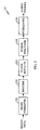
FIG. 2 is a block diagram of an embodiment ofTX data processor 114, which can be designed to implement various embodiments. Traffic data is received (again, typically in frames or packets) by aframe formatter 212 that formats each received frame in a particular manner. For example,frame formatter 212 can perform cycle redundancy check (CRC) coding on each frame of data and append the CRC bits to the frame.Frame formatter 212 typically further adds a number of code-tail bits to the end of each frame. The code-tail bits typically have values of zero and are used to set the subsequent encoder to a known state (e.g., all zeros) after the frame has been coded. Other frame formatting functions may also be performed byframe formatter 212. - The formatted frames are then provided to an
encoder 214 that codes each frame with a particular coding scheme to generate a corresponding frame of code symbols. For example,encoder 214 may perform convolutional or Turbo coding of a data frame. The particular coding scheme used is dependent on the particular system or standard being implemented and may be selectable (e.g., different coding schemes may be used for different types of services). The coding schemes used for the CDMA-2000 and W-CDMA systems are described in detail in the aforementioned standard documents. - The coded frames are then provided to a
symbol repeater 216. Depending on the number of code symbols generated for a particular frame and the capacity of the frame, zero or more symbols may be repeated. For example, in accordance with the CDMA-2000 standard, each symbol in a particular frame is repeated an integer number of time (i.e., M = 1, 2, 3, and so on), with the integer number M being selected such that the number of symbols after repetition minimally exceeds the capacity of the frame. Thus, if L code symbols are generated byencoder 214 for a particular frame and the frame has a capacity of N symbols (where N ≥ L ), then each symbol in the frame is repeated M times, where M is computed as M = ┌N/L┐. The symbol "┌ ┐" represents a ceiling operator, which provides the next greater integer. For example, if N/L = 5.2, then ┌N/L┐ = 6. - In many instances, the number of code symbols after repetition is not equal to the frame size (i.e., the number of code symbols exceeds the capacity of the frame). When this occurs, some of the code symbols are deleted (i.e., punctured) so that the resultant number of code symbols matches the capacity of the frame. Symbol repetition and puncturing are described in further detail below.
- The punctured frames are then provided to an
interleaver 220. The code symbols for each frame are typically written tointerleaver 220 in a particular write order (e.g., sequentially) and, after an entire frame has been stored, the code symbols are retrieved in a particular read order that is typically different from the write order to achieve the reordering of the symbols. Again, the interleaving scheme is typically defined by the particular system or standard being implemented. -
FIG. 3A is a flow diagram of a conventional symbol puncturing technique, which is described in the CDMA-2000 standard. Initially, the number of generated code symbols S and the number of required punctures P for a particular frame are determined, atstep 312. Referring back toFIG. 2 , S code symbols are generated bysymbol repeater 216 for a particular frame. If the frame has a capacity of N symbols and if S ≥ N, then P symbols are punctured, where P = S - N. If P is equal to zero then puncturing is not required. Otherwise, a puncture distance D is computed, atstep 314, based on the determined number of symbols S and the number of punctures P. The puncture distance is the number of symbols between two consecutive puncture symbols, plus 1, wherein the first puncture occurs at the D th symbol in the frame. For example, if D = 3, then there would be two unpunctured symbols before the next puncture. In accordance with the CDMA-2000 standard, the puncture distance D is computed as:
where the symbol "└┘" denotes the floor operator, which provides the next lower integer. For example, if S / P = 5.2, then └S/P┘ = 5. - Symbols in the frame are then punctured using the computed distance D. To perform a symbol puncture, symbols in the frame are counted, starting with the first symbol, and the D th symbol is punctured, at
step 316. After a symbol has been punctured, the number of required punctures P is decremented, atstep 318. A determination is then made whether all P symbols have been punctured, atstep 320. This determination can be made by simply checking whether P = 0. If all P symbols have been punctured, the process terminates. Otherwise, the process returns to step 316 and another symbol is punctured, again based on the previously computed distance D. - The conventional symbol puncturing technique described in
FIG. 3A can provide varied punctured results, depending on the particular values of S and P. Specifically, the punctured symbols may be evenly distributed throughout the frame for some values of S and P, or may be concentrated in one portion of the frame for some other values of S and P. These varied punctured results can be illustrated by the following simple examples. -
FIG. 3B is a diagram that illustrates a simple example using the conventional symbol puncturing technique described inFIG. 3A . In this specific example, 30 symbols are generated (i.e., S = 30) but (for this example) only 20 symbols can be fitted into a frame (i.e., N = 20). Thus, 10 symbols need to be punctured (i.e., P = S - N = 30 - 20 = 10). Using equation (1), the puncture distance D can be computed as 3. As shown inFIG. 3B , every 3rd symbol is punctured, as represented by the boxes with the X. In this specific example, the punctured symbols are uniformly distributed across the entire frame. -
FIG. 3C is a diagram that illustrates another simple example using the conventional symbol puncturing technique, but for different values of S and P. In this specific example, 31 symbols are generated (i.e., S = 31) and 20 symbols may be fitted into a frame (i.e., N = 20). Thus, 11 symbols need to be punctured (i.e., P = 11). Using equation (1), the puncture distance D can be computed as 2. As shown inFIG. 3C , every 2nd symbol is punctured, as represented by the boxes with the X, until all 11 symbols have been punctured. After the 11th symbol has been punctured, the remaining symbols are passed unmodified. As shown in this specific example, the punctured symbols are concentrated toward the front portion of the frame, while the back portion of the frame is left unchanged. The uneven distribution of punctured symbols results from puncturing the symbols with a high puncture rate (i.e., a short puncture distance D). -
FIGS. 3B and 3C illustrate the varied punctured results that can be obtained using the conventional puncturing technique. The puncturing pattern changes from a uniform distribution inFIG. 3B to an uneven distribution inFIG. 3C as a result of simply increasing the number of code symbols S by one. The conventional puncturing technique thus has "critical" points in which, because of the discrete floor operator └┘, the puncturing distance D changes by one whole unit when S is increased by one. - The uneven distribution of the punctured symbols in
FIG. 3C can result in performance degradation at the receiver unit. Deletion of symbols is equivalent to reducing the transmit power for those symbols to zero. For convolutionally coded data, a Viterbi decoder is used at the receiver unit to decode the symbols. The Viterbi decoder provides improved performance (i.e., better error correcting capability) if code symbols received in error are more uniformly spread across an entire frame. By puncturing more symbols in one portion of a frame, the Viterbi decoder may not be able to correct symbol errors in that portion of the frame, and an entire frame may be declared erased (i.e., received in error). -
FIG. 4A is a flow diagram of an embodiment of a symbol puncturing technique in accordance with one embodiment. Initially, the number of generated code symbols S and the number of required punctures P for a particular frame are determined, atstep 412. If the frame has a capacity of N symbols and if S ≥ N , then P symbols are punctured, where P = S - N. If P is equal to zero then puncturing is not required. Otherwise, the puncture distance D is computed based on the determined number of symbols S and the number of punctures P, atstep 414. The puncture distance D can be computed using equation (1). - Symbols in the frame are then punctured using the computed distance D. To perform a symbol puncture, symbols in the frame are counted, initially starting with the first symbol, and the D th symbol is punctured, at
step 416. After a symbol has been punctured, the number of remaining symbols is determined (i.e., S n+1 = Sn - D) and the number of required punctures P is decremented (i.e., P n+1 = Pn - 1), atstep 418. A determination is then made whether all P symbols have been punctured, atstep 420. Again, this determination can be made by simply checking whether P = 0. If all P symbols have been punctured, the process terminates. Otherwise, the process returns to step 414 and the puncture distance D is recomputed based on the updated values for S and P. Symbols are counted from there onwards and the Dth symbol is punctured, atstep 416. The process then continues until all P symbols have been punctured. - The symbol puncturing technique shown in
FIG. 4A recomputes the puncture rate (i.e., the puncture distance D) in "real-time" after each puncture. The new "puncture distance" (i.e., the number of symbols until the next puncture) is computed based on the number of symbols still remaining and the number of punctures still to be performed. Each computation generates a new puncture distance D that attempts to uniformly distribute the remaining symbol punctures. - For a clearer understanding, the puncturing technique described in
FIG. 4A can be applied to the example shown inFIG. 3B in which 31 code symbols are generated (i.e., L = 31) and the frame has a capacity of 20 symbols (i.e., N = 20). Again, 11 symbol punctures are required. Table 1 lists the parameters S, P, and D for each puncture (i.e., for each pass through the loop shown inFIG. 4A ).Table 1 Parameters S P D Start 31 11 D = └31/11┘ = 2 After 1st puncture 29 10 D = └29/10┘ = 2 After 2nd puncture 27 9 D = └27/9┘ = 3 After 3rd puncture 24 8 D = └24/8┘ = 3 After 4th puncture 21 7 D = └21/7┘ = 3 After 5th puncture 18 6 D = └18/6┘ = 3 After 6th puncture 15 5 D = └15/5┘ = 3 After 7th puncture 12 4 D = └12/4┘ = 3 After 8th puncture 9 3 D = └9/3┘ = 3 After 9th puncture 6 2 D = └6/2┘ = 3 After 10th puncture 3 1 D = └3/1┘ = 3 -
FIG. 4B is a diagram that shows the results of the puncturing example described in Table 1. For the first two punctures, the distance is computed as two (i.e., D = 2). After the second symbol puncture, the remaining symbols are punctured with a distance of three (i.e., D = 3). When comparing the puncture pattern shown inFIG. 4B versus the puncture pattern shown inFig. 3C , it can be observed that the symbol puncturing technique of the invention provides a much more even distribution of punctured symbols. -
FIG. 5A is a flow diagram illustrating another symbol puncturing technique. Initially, the number of generated code symbols S and the number of required punctures P for a particular frame are determined, atstep 512. Again, if the frame has a capacity of N symbols and if S ≥ N , then P symbols are punctured, where P = S - N. IfP is equal to zero then puncturing is not required. Otherwise, two puncture distances D1 and D2 are computed, atstep 514, based on the determined number of symbols S and the number of punctures P. - For every integer S and P, the following equality can be shown to be true:

Based on equation (2), two puncture distances D1 and D2 can be computed as:

- The number of punctures P1 using puncture distance D1 and the number of punctures P2 using puncture distance D2 are then computed, at
step 516. The number of punctures P1 and P2 can be computed as:


- Once the puncture distances D1 and D2 and the number of punctures P1 and P2 have been computed, one of the computed puncture distances is selected, at
step 518. Various methods can be used to select either D1 or D2, as described below. A symbol in the frame is then punctured using the selected puncture distance. Again, to perform a symbol puncture, symbols in the frame are counted, starting with first symbol in the frame or the last punctured symbol, and the D1 th or D2 th symbol is punctured, atstep 520. After a symbol has been punctured, the required number of punctures P1 or P2 is decremented, depending on which puncture distance has been selected, atstep 522. Specifically, P1 is decremented if D1 is selected and P2 is decremented if D2 is selected. - A determination is then made whether all P1 and P2 symbols have been punctured, at
step 524. This determination can be made by simply checking whether P1 = 0 and P2 = 0. If all P1 and P2 symbols have been punctured, the process terminates. Otherwise, the process returns to step 518 and one of the puncture distances is selected. The process then continues until all P1 and P2 symbols have been punctured. - For a better understanding, the puncturing technique described in
FIG. 5A can be applied to the specific example described above in which 31 symbols are generated (i.e., S = 31), 20 symbols may be fitted into a frame (i.e., N = 20), and 11 symbols need to be punctured (i.e., P = 11). Using equations (3) and (4), the puncture distances D1 and D2 can be computed as:


- As noted above, various methods can be used to select which one of the puncture distances, D1 or D2, to use for the next puncture. In one example, one of the puncture distances (e.g., D1) is selected and used for a corresponding number of times (e.g., P1) and then the other puncture distance (e.g., D2) is selected and used for the remaining punctures (e.g., P2). For the above example, two punctures (P1) can be performed at the distance of two (D1) followed by nine punctures (P2) at the distance of three (D2).
- In another example, the puncture distances D1 and D2 are alternately selected and used until all punctures at one of the distances are achieved. The remaining punctures are then performed using the other distance. For the above example, the punctures can be performed using the distances of 2, 3, 2, 3, 3, 3, and so on.
- In yet another example, the P1 punctures at the distance of D1 are approximately distributed among the P2 punctures at the distance of D2. For example, if the ratio of P1 to P2 is R, then R punctures are performed using the distance D1 for each puncture using the distance D2. For the above example, two punctures are performed using the distance of two and nine punctures are performed using the distance of three. Thus, four or five punctures can be performed using the distance of three for each puncture at the distance of two.
- In yet another example, a weighting algorithm can be used to distribute the P1 punctures at the distance of D1 among the P2 punctures at the distance of D2. Let intermediate value F = P1*N2 - P2*N1, wherein N1 and N2 are incremental counters indicating the number of punctures at an iterative round. The maximum values for N1 and N2 are chosen so that the puncturing distances P1 and P2 are distributed within the frame. At the beginning of every frame and after every puncture, and while N1 + N2 < P, the distance D2 is chosen and N2 is incremented by 1 if F < 0, otherwise the distance D1 is chosen and N1 is incremented by 1.
- In yet another example, the symbol punctures are (approximately) uniformly distributed over the entire frame. In one specific implementation of this example, a "wrap-around" accumulator can be used to store a value that is then used to select the puncture distance for the next puncture. The accumulator is designed to store a value ranging from zero to B, where B is typically a power of twos (e.g., 256, 512, 1024, or some other value). B may also be selected to be larger than or equal to the size of the frame (i.e., B ≥ N). Initially, the smaller value of the punctures P1 and P2 is determined. Then an accumulation value A is computed as the ratio of the smaller P1 or P2 value to the larger P1 or P2 value, multiplied by the value B. For example, if P1 = 2, P2 = 9, and B = 1024, then A = (P1/P2)·B = (2/9)•1024 ≡ 227. Thereafter, before each puncture, the accumulation value A is added to the value in the accumulator and stored back to the accumulator. If the accumulator wraps around after the accumulation with the value A, then the puncture distance corresponding to the smaller P1 or P2 value is selected for the next symbol puncture.
- For the above example, the values in the accumulator can be computed as 227, 454, 681, 908, 111, 338, 565, 792,1019,222, and 449, before the 1st, 2rd, 3rd, 4th, 5th, 6th, 7th, 8th, 9th, 10th, and 11th symbol punctures, respectively. The puncture distance D1 is selected for the 5th and 10th symbol punctures since the accumulator has wrapped around and has values of 111 and 222, respectively. By initializing the accumulator with a value other than zero, the first puncture at the distance of two can be different. For example, if the accumulator is initialized a the value of 512, then the 3rd and 7th punctures are performed at the distance of two and the remaining punctures are performed at the distance of three.
- For the example shown in
FIG. 5A , the computational costs are maintained low. Specifically, only one division operation is performed atstep 514 to compute the puncture distances D1 and D2, which is the same number of division operation as for the conventional puncturing technique shown inFIG. 3A . Thus, the example shown inFIG. 5A provides improved performance at equivalent computation costs. -
FIG. 5B is a diagram that shows the results of the puncturing example described above using the symbol puncturing technique shown inFIG. 5A . In this diagram, the 1st and 6th punctures are performed using the distance of two and the other punctures are performed using the distance of three. The punctures at distances D1 and D2 can also be distributed in various other manners, some of which are described above. - The symbol puncturing technique described in
FIG. 5A can be generalized to cover N puncture distances. The N puncture distances D1 through DN can be computed based on S and P (and possibly other parameters) and used to puncture S code symbols. For improved puncturing results (e.g., a more even distribution of the symbol punctures), each of the distances D1 through DN can be selected to be greater than or equal to a minimum puncture distance Dmin defined as:
- For the N puncture distances, the number of symbol punctures to be performed at each of the puncture distances D1 through DN is then determined. The P1 through PN symbol punctures at the distances of D1 through DN, respectively, are selected such that the following conditions are satisfied:


- As noted above, a complementary process is performed at the receiver unit to account for the symbol puncturing performed at the transmitter unit. Specifically, erasures (i.e., "don't knows") are inserted in place of symbols that have been punctured. The erasures are given appropriate weighting during the subsequent decoding process.
- Prior to the decoding, N code symbols are received for a particular frame. The number of symbol punctures P that had been performed among S code symbols to generate the N received symbols are then determined. A number of puncture distances, D1 through DN, is then computed based on S and P. P1 through PN symbol punctures that had been performed at the distances of D1 through DN, respectively, are also determined. A puncturing pattern used to puncture the S symbols to generate the N received symbols is then derived based on the P1 through PN symbol punctures at the distances of D1 through DN, respectively. P erasures are then inserted among the N received symbols based on the derived puncturing pattern to generate S recovered symbols, which are then decoded with a particular decoding scheme. Again, for a more even distribution of the erasures/symbol punctures, each of the distances D1 through DN can be selected to be greater than or equal to a minimum puncture distance Dmin defined above.
- As a simple example, for the example in which P1 symbol punctures at the distance of D1 are performed followed by P2 symbol punctures at the distance of D2, the receiver unit inserts P1 erasures, one after each D1th received symbols, then inserts P2 erasures, one after each D2th received symbols. The S recovered symbols are then decoded with a particular decoding scheme complementary to the coding scheme used at the transmitter unit.
-
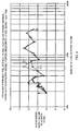
FIG. 6 shows plots of the performance achieved with the conventional puncturing technique described inFIG. 3A versus the performance achieved with a puncturing technique in accordance with one embodiment. The performance results are for the forward link (i.e., from a base station to a user terminal) in the CDMA-2000 system. The horizontal axis represents the number of data and CRC bits for each frame. For the CDMA-2000 system, frames of various sizes are available for use, with the frame sizes being an integer multiple of a basic frame size (e.g., available frame sizes are 768•K, where K = 1, 2, ...). The vertical axis represents the average required energy-per-bit-to-total-noise-plus-interference Eb/(No + loc) for a frame error rate (FER) of 1%. - The simulation results for the conventional puncturing technique are shown by a dashed
line 610 inFIG. 6 . The results indicate some peaks at approximately periodic intervals. For example, peaks are observed at approximately 300, 600, 1200, and 2400 bits. These peaks result from the uneven symbol puncturing generated by the conventional puncturing technique. The peaks represent the need for a higher average energy per bit Eb to maintain the same FER of 1%. - The simulation results for the puncturing technique in accordance with one example are shown by a
solid line 612 inFIG. 6 . The results indicate improvement in performance at some of the peaks. In particular, improvements of approximately 0.5 dB and 1.0 dB are observed at 300 and 600 bits, respectively. - In one example puncturing may be advantageously performed without using numbers of symbol punctures P1 and P2 or puncture distances D1 and D2. An accumulator is configured to wrap around after it has been incremented to a value that is greater than or equal to S, each increment being of size P, wherein P is a desired number of symbol punctures, S is a total number of received symbols, and N is a frame capacity in symbols (i.e., a number of symbols remaining after puncturing). The accumulator is thus a modulo-S accumulator. A symbol index is advantageously initialized to one. The symbol index is incremented by one each time the accumulator is incremented by P, until the symbol index reaches the value S. The process is advantageously begun with a puncture. Each time the accumulator wraps around, a puncture is performed. Nevertheless, one of ordinary skill in the art would readily appreciate that the process need not be initiated with a puncture. Additionally, while the accumulator is advantageously initialized to S, those of skill would understand that the accumulator may be initialized to any value, such as, e.g., zero. Moreover, those of skill would appreciate that the process may instead be run in reverse, so that the symbol index is initially set to the value S, and decremented by one each time the accumulator is incremented by P, until the symbol index reaches one.
- In an example of the just-described example, ten symbols are received and the frame capacity is only seven symbols, so three symbols must be punctured. Accordingly, P is 3, N is seven, and S is ten. The values for the accumulator and the symbol index are shown Table 2 below.
Table 2 Accumulator Value (Initialized to 10) Symbol Index (Initialized to 1) 0 (10-10) PUNCTURE (X) 3 2 6 3 9 4 2 (12-10) PUNCTURE (X) 5 6 8 7 1 (11-10) PUNCTURE (X) 4 9 7 10 0 STOP - A flowchart illustrating algorithm steps in accordance with the just-described example is shown in
FIG. 7 . In step 700 a field denoted ACC_VALUE is initialized to the value S, and a field denoted SYMBOL_IDX is initialized to one. In other examples ACC_VALUE is initialized to values other than S, such as, e.g., zero. Control flow then proceeds to step 702. Instep 702 ACC_VALUE is compared with the number S. If ACC_VALUE is greater than or equal to S, control flow proceeds to step 704. If, on the other hand, ACC_VALUE is not greater than or equal to S, control flow proceeds to step 706. Instep 704 ACC_VALUE is decremented by S (i.e., ACC_VALUE is set equal to the difference between ACC_VALUE and S). Control flow then proceeds to step 708. In step 708 a symbol corresponding to the value of SYMBOL_IDX is punctured. Control flow then proceeds to step 706. Instep 706 ACC_VALUE is incremented by P (i.e., ACC_VALUR is set equal to the sum of ACC_VALUE and P). Control flow then proceeds to step 710. Instep 710 SYMBOL_IDX is incremented by one (i.e., SYMBOL_IDX is set equal to the sum of SYMBOL_IDX and one). Control flow then proceeds to step 712. Instep 714 SYMBOL_IDX is compared with the value S. If SYMBOL_IDX is greater than S, control flow proceeds to step 712, at which the process stops. If, on the other hand, SYMBOL_IDX is not greater than S, control flow returns to step 702 and the process continues. In other embodiments SYMBOL_IDX is initialized to the value S and the algorithm terminates when SYMBOL_IDX drops below the one. - In an alternate embodiment, wherein the values S and P have a common denominator M, the value S/M may be substituted for the value S, and the value P/M may be substituted for the value P in the flowchart of
FIG. 7 for ACC_VALUE field (but not in the SYMBOL_IDX field). Accordingly, the ACC_VALUE field is initialized to S/M and a modulo-S/M register is used for the accumulator. The accumulator is incremented by P/M each increment. Every time the accumulator value exceeds S/M, a modulo-S/M operation is performed and a symbol puncture is done. - In one embodiment symbol puncturing is advantageously combined with symbol repetition as illustrated by the flowchart of
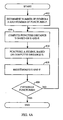
FIG. 8 . In accordance with this embodiment, N is defined as the number of symbols after repetition and puncturing (i.e., the desired frame length in symbols), and L is defined as the input length before repetition (i.e., the frame size in symbols at the output of the encoder (not shown)). It would be readily appreciated by those of skill in the art that, in the embodiments described above with reference toFIG. 7 , S, which is equal to N + P, is also equal to k*L, with k being defined as an integer number of repetitions, and S. - In
FIG. 8 , in step 800 a symbol index, having a field denoted SYMBOL_IDX, is initialized to zero, and an accumulator, having a field denoted ACC_VALUE, is also initialized to zero. Control flow then proceeds to step 802. In step 802 the algorithm determines whether ACC_VALUE is less than N. If ACC_VALUE is less than N, control flow proceeds to step 804. If, on the other hand, ACC_VALUE is not less than N, control flow proceeds to step 806. Instep 804 ACC_VALUE is incremented by L. Control flow then proceeds to step 808. Instep 808 the value of SYMBOL_IDX is output. The algorithm then returns to step 802 to perform another iteration. Instep 806 SYMBOL_IDX is incremented by one, and ACC_VALUE is decremented by N. Control flow then proceeds to step 810. Instep 810 the algorithm determines whether SYMBOL_IDX is greater than or equal to L. If SYMBOL_IDX is greater than or equal to L, control flow proceeds to step 812, and the algorithm stops. If, on the other hand, SYMBOL_IDX is not greater than or equal to L, the algorithm returns to step 802 to perform another iteration. - It would be understood by those of skill that SYMBOL_IDX specifies a symbol position in the frame with length L that is input to combined repeating and puncturing logic (not shown). Each
time step 808 is performed (i.e., SYMBOL_IDX is output), the symbol at location SYMBOL_IDX is repeated a number of times in the frame with length N that is generated by the combined repeating and puncturing logic. In a particular embodiment, the symbol is repeated an integer number times equal to the quotient N/L (rounded up or down if N/L is not an integer, the rounding up and down being advantageously alternated each time SYMBOL_IDX is incremented). Those of skill would understand that the output frame of length N may be arranged in other ways without departing from the scope of the present invention. - In accordance with one embodiment, symbol repetition and puncturing is performed according to the following pseudo-code steps:
 L= size of frame at output of encoder (input buffer)
 N= desired frame length (output buffer)
 IN_SYM= 0;    #Index to the input buffer
 ACC= 0;
 while (IN_SYM < L)
        while (ACC < N)
               output symbol IN_SYM
               ACC= ACC+L;
        end while
        IN_SYM= IN_SYM + 1;
        ACC= ACC-N;
 end while
Claims (13)
- A transmit data processing method in a communications system, the method comprising the following steps for combined repeating and puncturing of symbols:(a) receiving a first number of symbols L to be fitted into an output frame having a capacity of N symbols;(b) initializing (800) to zero an accumulator value and a symbol index value;(c) if the accumulator value is less than N, increasing (804) the accumulator value by L and repeating (808) in the output frame a symbol from a location in the first number of symbols corresponding to the symbol index value, the increasing and repeating being performed until the accumulator value is not less than N;(d) if the accumulator value is greater than or equal to N, increasing (806) the symbol index value by one and decreasing the accumulator value by N; and(e) repeating (810) (c)- (d) until the symbol index value is greater than or equal to L.
- The method of claim 1 further comprising, prior to step (a):performing cycle redundancy check (CRC) coding on a frame of traffic data to generate a formatted frame; andencoding the formatted frame to generate the first number of symbols L.
- The method of claim 2 further comprising adding at least one code-tail bit to the end of the frame of traffic data to generate the formatted frame.
- The method of claim 1 wherein the step of encoding the formatted frame comprises performing convolutional coding on the formatted frame.
- The method of claim 1 wherein the step of encoding the formatted frame comprises performing turbo coding on the formatted frame.
- The method of claim 1 wherein the communications system is either a cdma2000 system or a W-CDMA system (100).
- A transmit data processor for use in a communications system, comprising:means for receiving a first number of symbols L to be fitted into an output frame having a capacity of N symbols (212);means for initializing to zero an accumulator value and a symbol index value (216, 218);means for, if the accumulator value is less than N, increasing the accumulator value by L and repeating in the output frame a symbol from a location in the first number of symbols corresponding to the symbol index value, the increasing and repeating being performed until the accumulator value is not less than N (216, 218);means for, if the accumulator value is greater than or equal to N, increasing the symbol index value by one and decreasing the accumulator value by N; andmeans for repeating the steps of increasing of the accumulator value by L, repeating the symbols in the output frame, increasing the symbol index value by one, and decreasing the accumulator value by N until the symbol index value is greater than or equal to L (216, 218).
- The transmit data processor of claim 7 further comprising:a frame formatter (212) for performing cycle redundancy check (CRC) coding on a frame of traffic data to generate a formatted frame; andan encoder (214) for encoding the formatted frame to generate the first number of symbols L.
- The transmit data processor of claim 8 wherein the encoder (214) performs convolutional coding on the formatted frame.
- The transmit data processor of claim 8 wherein the encoder (214) performs turbo coding on the formatted frame.
- The transmit data processor of claim 7 wherein at least one of the means recited in claim 7 is a combined symbol repeating and puncturing logic (216, 218).
- The transmit data processor of claim 8 wherein the frame formatter further adds at least one code-tail bit to the end of the frame of traffic data to generate the formatted frame.
- The transmit data processor of claim 7 wherein the communications system is either a cdma2000 system or a W-CDMA system (100).
Applications Claiming Priority (3)
| Application Number | Priority Date | Filing Date | Title |
|---|---|---|---|
| US09/618,952 US6675347B1 (en) | 2000-07-19 | 2000-07-19 | Method and apparatus for combined puncturing and repeating of code symbols in a communications system |
| US618952 | 2000-07-19 | ||
| PCT/US2001/022757 WO2002009294A2 (en) | 2000-07-19 | 2001-07-17 | Method and apparatus for combined puncturing and repeating of code symbols in a communications system |
Publications (2)
| Publication Number | Publication Date |
|---|---|
| EP1301994A2 EP1301994A2 (en) | 2003-04-16 |
| EP1301994B1 true EP1301994B1 (en) | 2010-08-25 |
Family
ID=24479817
Family Applications (1)
| Application Number | Title | Priority Date | Filing Date |
|---|---|---|---|
| EP01953552A Expired - Lifetime EP1301994B1 (en) | 2000-07-19 | 2001-07-17 | Method and apparatus for combined puncturing and repeating of code symbols in a communications system |
Country Status (11)
| Country | Link |
|---|---|
| US (1) | US6675347B1 (en) |
| EP (1) | EP1301994B1 (en) |
| JP (1) | JP2004505489A (en) |
| KR (1) | KR100736131B1 (en) |
| CN (1) | CN1258886C (en) |
| AT (1) | ATE479233T1 (en) |
| AU (1) | AU2001275989A1 (en) |
| BR (1) | BR0112578A (en) |
| DE (1) | DE60142905D1 (en) |
| TW (1) | TW515174B (en) |
| WO (1) | WO2002009294A2 (en) |
Families Citing this family (15)
| Publication number | Priority date | Publication date | Assignee | Title |
|---|---|---|---|---|
| EP1277287A4 (en) * | 2000-04-21 | 2004-03-03 | Samsung Electronics Co Ltd | FLEXIBLE METHOD AND APPARATUS FOR CORRESPONDING BIT RATES IN A DATA COMMUNICATION SYSTEM |
| US6888851B1 (en) * | 2000-06-07 | 2005-05-03 | Via Telecom Co., Ltd. | Frame matching method |
| US7437654B2 (en) * | 2000-11-29 | 2008-10-14 | Lucent Technologies Inc. | Sub-packet adaptation in a wireless communication system |
| US7188300B2 (en) * | 2001-05-01 | 2007-03-06 | Telefonaktiebolaget Lm Ericsson (Publ) | Flexible layer one for radio interface to PLMN |
| BR0205740A (en) * | 2001-07-12 | 2004-02-03 | Samsung Electronics Co Ltd | Reverse Transmission Apparatus and Method for Improving Transmission Quality in a Data Communication System |
| WO2003085873A2 (en) * | 2002-04-08 | 2003-10-16 | Siemens Aktiengesellschaft | Method and communications device for adapting the data transfer rate in a communications device |
| BRPI0318842B1 (en) * | 2002-04-08 | 2017-01-17 | Siemens Ag | process for equalizing the data rate on a communication device and communication device |
| JP4909498B2 (en) * | 2004-02-27 | 2012-04-04 | 日本電気株式会社 | Interleave parameter calculation method / program / program recording medium / device, mobile phone |
| US7284185B2 (en) * | 2004-10-08 | 2007-10-16 | Telefonaktiebolaget Lm Ericsson (Publ) | Puncturing/depuncturing using compressed differential puncturing pattern |
| KR100605988B1 (en) * | 2005-01-05 | 2006-07-28 | 삼성전자주식회사 | Efficient Drilling Method for Low Density Parity Check Codes |
| KR101102396B1 (en) | 2006-02-08 | 2012-01-05 | 엘지전자 주식회사 | Codeword Size Matching Method and Transmission Device in Mobile Communication System |
| US8352843B2 (en) | 2007-03-16 | 2013-01-08 | Qualcomm Incorporated | Method and apparatus for coding a communication signal |
| CN101079678B (en) * | 2007-06-29 | 2012-11-21 | 重庆重邮信科通信技术有限公司 | A speed matching algorithm for computing and identifying hole/repeated bit position |
| JP5721316B2 (en) | 2009-03-03 | 2015-05-20 | シャープ株式会社 | Transmitting apparatus, receiving apparatus, and communication system |
| RU2012109385A (en) * | 2012-03-12 | 2013-09-20 | ЭлЭсАй Корпорейшн | OPTIMIZATION OF DATA PROCESSORS USING IRREGULAR COMBINATIONS |
Family Cites Families (9)
| Publication number | Priority date | Publication date | Assignee | Title |
|---|---|---|---|---|
| US4024508A (en) * | 1975-06-19 | 1977-05-17 | Honeywell Information Systems, Inc. | Database instruction find serial |
| US4901307A (en) | 1986-10-17 | 1990-02-13 | Qualcomm, Inc. | Spread spectrum multiple access communication system using satellite or terrestrial repeaters |
| US5103459B1 (en) | 1990-06-25 | 1999-07-06 | Qualcomm Inc | System and method for generating signal waveforms in a cdma cellular telephone system |
| FI104673B (en) * | 1997-10-24 | 2000-04-14 | Nokia Mobile Phones Ltd | Method of transforming the data rate of a signal and transmitter |
| US6084917A (en) * | 1997-12-16 | 2000-07-04 | Integrated Telecom Express | Circuit for configuring and dynamically adapting data and energy parameters in a multi-channel communications system |
| KR100407342B1 (en) * | 1998-05-30 | 2003-11-28 | 삼성전자주식회사 | Apparaus and method for communication in cdma communication system |
| AU763882B2 (en) * | 1998-10-07 | 2003-07-31 | Siemens Aktiengesellschaft | Apparatus and method for transmitting punctured or repeated data |
| CA2394263C (en) | 1999-12-20 | 2006-06-06 | Research In Motion Limited | Hybrid automatic repeat request system and method |
| US6690734B1 (en) | 2000-06-02 | 2004-02-10 | Qualcomm, Incorporated | Method and apparatus for puncturing code symbols in a communications system |
-
2000
- 2000-07-19 US US09/618,952 patent/US6675347B1/en not_active Expired - Lifetime
-
2001
- 2001-07-17 DE DE60142905T patent/DE60142905D1/en not_active Expired - Lifetime
- 2001-07-17 BR BR0112578-8A patent/BR0112578A/en not_active IP Right Cessation
- 2001-07-17 AU AU2001275989A patent/AU2001275989A1/en not_active Abandoned
- 2001-07-17 JP JP2002514897A patent/JP2004505489A/en active Pending
- 2001-07-17 AT AT01953552T patent/ATE479233T1/en not_active IP Right Cessation
- 2001-07-17 EP EP01953552A patent/EP1301994B1/en not_active Expired - Lifetime
- 2001-07-17 KR KR1020037000828A patent/KR100736131B1/en not_active Expired - Fee Related
- 2001-07-17 WO PCT/US2001/022757 patent/WO2002009294A2/en not_active Ceased
- 2001-07-17 CN CNB01812934XA patent/CN1258886C/en not_active Expired - Fee Related
- 2001-07-19 TW TW090117616A patent/TW515174B/en not_active IP Right Cessation
Non-Patent Citations (1)
| Title |
|---|
| "UMTS Terrestrial Radio Access Network (UTRAN); UTRA FDD, multiplexing, channel coding and interleaving description", UMTS XX.04 V1.0.0 (1999-02), February 1999 (1999-02-01), ETSI, XP002181831 * |
Also Published As
| Publication number | Publication date |
|---|---|
| JP2004505489A (en) | 2004-02-19 |
| DE60142905D1 (en) | 2010-10-07 |
| WO2002009294A3 (en) | 2003-01-16 |
| US6675347B1 (en) | 2004-01-06 |
| BR0112578A (en) | 2003-12-30 |
| WO2002009294A2 (en) | 2002-01-31 |
| EP1301994A2 (en) | 2003-04-16 |
| CN1443399A (en) | 2003-09-17 |
| TW515174B (en) | 2002-12-21 |
| HK1056443A1 (en) | 2004-02-13 |
| AU2001275989A1 (en) | 2002-02-05 |
| KR20030040367A (en) | 2003-05-22 |
| ATE479233T1 (en) | 2010-09-15 |
| KR100736131B1 (en) | 2007-07-06 |
| CN1258886C (en) | 2006-06-07 |
Similar Documents
| Publication | Publication Date | Title |
|---|---|---|
| JP5149418B2 (en) | Method and apparatus for puncturing code symbols in a communication system | |
| KR100860245B1 (en) | Method and apparatus for performing reverse rate matching in code division multiple access system | |
| EP2134038B1 (en) | Method for improving TFCI transportation performance | |
| AU751048B2 (en) | Method and apparatus for providing error protection for over the air file transfer | |
| EP1101321B1 (en) | Rate matching device and method for a data communication system | |
| JP3415120B2 (en) | Channel coding apparatus and method for rate matching | |
| US6675347B1 (en) | Method and apparatus for combined puncturing and repeating of code symbols in a communications system | |
| US7415263B2 (en) | Receiver for a wireless communication device | |
| EP2139140A2 (en) | Mobile radio apparatus employing data rate matching | |
| US20020085659A1 (en) | Flexible data rate matching apparatus and method in a data communication system | |
| AU2001252744A1 (en) | Flexible data rate matching apparatus and method in a data communication system | |
| US6614850B1 (en) | Method and apparatus for puncturing code symbols in a communications system | |
| EP2157701B1 (en) | Method and apparatus for puncturing code symbols in a communication system | |
| CA2414363A1 (en) | Method and apparatus for flexible data rate matching by symbol insertion for a data communication system | |
| WO2001093431A1 (en) | Method and apparatus for puncturing code symbols in a communications system |
Legal Events
| Date | Code | Title | Description |
|---|---|---|---|
| PUAI | Public reference made under article 153(3) epc to a published international application that has entered the european phase |
Free format text: ORIGINAL CODE: 0009012 |
|
| 17P | Request for examination filed |
Effective date: 20030129 |
|
| AK | Designated contracting states |
Designated state(s): AT BE CH CY DE DK ES FI FR GB GR IE IT LI LU MC NL PT SE TR |
|
| AX | Request for extension of the european patent |
Extension state: AL LT LV MK RO SI |
|
| 17Q | First examination report despatched |
Effective date: 20090603 |
|
| GRAP | Despatch of communication of intention to grant a patent |
Free format text: ORIGINAL CODE: EPIDOSNIGR1 |
|
| GRAS | Grant fee paid |
Free format text: ORIGINAL CODE: EPIDOSNIGR3 |
|
| GRAA | (expected) grant |
Free format text: ORIGINAL CODE: 0009210 |
|
| AK | Designated contracting states |
Kind code of ref document: B1 Designated state(s): AT BE CH CY DE DK ES FI FR GB GR IE IT LI LU MC NL PT SE TR |
|
| REG | Reference to a national code |
Ref country code: GB Ref legal event code: FG4D |
|
| REG | Reference to a national code |
Ref country code: CH Ref legal event code: EP |
|
| REG | Reference to a national code |
Ref country code: IE Ref legal event code: FG4D |
|
| REF | Corresponds to: |
Ref document number: 60142905 Country of ref document: DE Date of ref document: 20101007 Kind code of ref document: P |
|
| REG | Reference to a national code |
Ref country code: NL Ref legal event code: VDEP Effective date: 20100825 |
|
| PG25 | Lapsed in a contracting state [announced via postgrant information from national office to epo] |
Ref country code: FI Free format text: LAPSE BECAUSE OF FAILURE TO SUBMIT A TRANSLATION OF THE DESCRIPTION OR TO PAY THE FEE WITHIN THE PRESCRIBED TIME-LIMIT Effective date: 20100825 Ref country code: AT Free format text: LAPSE BECAUSE OF FAILURE TO SUBMIT A TRANSLATION OF THE DESCRIPTION OR TO PAY THE FEE WITHIN THE PRESCRIBED TIME-LIMIT Effective date: 20100825 |
|
| PG25 | Lapsed in a contracting state [announced via postgrant information from national office to epo] |
Ref country code: PT Free format text: LAPSE BECAUSE OF FAILURE TO SUBMIT A TRANSLATION OF THE DESCRIPTION OR TO PAY THE FEE WITHIN THE PRESCRIBED TIME-LIMIT Effective date: 20101227 Ref country code: CY Free format text: LAPSE BECAUSE OF FAILURE TO SUBMIT A TRANSLATION OF THE DESCRIPTION OR TO PAY THE FEE WITHIN THE PRESCRIBED TIME-LIMIT Effective date: 20100825 |
|
| PG25 | Lapsed in a contracting state [announced via postgrant information from national office to epo] |
Ref country code: SE Free format text: LAPSE BECAUSE OF FAILURE TO SUBMIT A TRANSLATION OF THE DESCRIPTION OR TO PAY THE FEE WITHIN THE PRESCRIBED TIME-LIMIT Effective date: 20100825 Ref country code: BE Free format text: LAPSE BECAUSE OF FAILURE TO SUBMIT A TRANSLATION OF THE DESCRIPTION OR TO PAY THE FEE WITHIN THE PRESCRIBED TIME-LIMIT Effective date: 20100825 Ref country code: GR Free format text: LAPSE BECAUSE OF FAILURE TO SUBMIT A TRANSLATION OF THE DESCRIPTION OR TO PAY THE FEE WITHIN THE PRESCRIBED TIME-LIMIT Effective date: 20101126 Ref country code: NL Free format text: LAPSE BECAUSE OF FAILURE TO SUBMIT A TRANSLATION OF THE DESCRIPTION OR TO PAY THE FEE WITHIN THE PRESCRIBED TIME-LIMIT Effective date: 20100825 |
|
| PG25 | Lapsed in a contracting state [announced via postgrant information from national office to epo] |
Ref country code: DK Free format text: LAPSE BECAUSE OF FAILURE TO SUBMIT A TRANSLATION OF THE DESCRIPTION OR TO PAY THE FEE WITHIN THE PRESCRIBED TIME-LIMIT Effective date: 20100825 |
|
| PG25 | Lapsed in a contracting state [announced via postgrant information from national office to epo] |
Ref country code: IT Free format text: LAPSE BECAUSE OF FAILURE TO SUBMIT A TRANSLATION OF THE DESCRIPTION OR TO PAY THE FEE WITHIN THE PRESCRIBED TIME-LIMIT Effective date: 20100825 |
|
| PG25 | Lapsed in a contracting state [announced via postgrant information from national office to epo] |
Ref country code: ES Free format text: LAPSE BECAUSE OF FAILURE TO SUBMIT A TRANSLATION OF THE DESCRIPTION OR TO PAY THE FEE WITHIN THE PRESCRIBED TIME-LIMIT Effective date: 20101206 |
|
| PLBE | No opposition filed within time limit |
Free format text: ORIGINAL CODE: 0009261 |
|
| STAA | Information on the status of an ep patent application or granted ep patent |
Free format text: STATUS: NO OPPOSITION FILED WITHIN TIME LIMIT |
|
| 26N | No opposition filed |
Effective date: 20110526 |
|
| REG | Reference to a national code |
Ref country code: DE Ref legal event code: R097 Ref document number: 60142905 Country of ref document: DE Effective date: 20110526 |
|
| PG25 | Lapsed in a contracting state [announced via postgrant information from national office to epo] |
Ref country code: MC Free format text: LAPSE BECAUSE OF NON-PAYMENT OF DUE FEES Effective date: 20110731 |
|
| REG | Reference to a national code |
Ref country code: CH Ref legal event code: PL |
|
| GBPC | Gb: european patent ceased through non-payment of renewal fee |
Effective date: 20110717 |
|
| REG | Reference to a national code |
Ref country code: FR Ref legal event code: ST Effective date: 20120330 |
|
| REG | Reference to a national code |
Ref country code: IE Ref legal event code: MM4A |
|
| PG25 | Lapsed in a contracting state [announced via postgrant information from national office to epo] |
Ref country code: DE Free format text: LAPSE BECAUSE OF NON-PAYMENT OF DUE FEES Effective date: 20120201 Ref country code: FR Free format text: LAPSE BECAUSE OF NON-PAYMENT OF DUE FEES Effective date: 20110801 Ref country code: LI Free format text: LAPSE BECAUSE OF NON-PAYMENT OF DUE FEES Effective date: 20110731 Ref country code: CH Free format text: LAPSE BECAUSE OF NON-PAYMENT OF DUE FEES Effective date: 20110731 |
|
| REG | Reference to a national code |
Ref country code: DE Ref legal event code: R119 Ref document number: 60142905 Country of ref document: DE Effective date: 20120201 |
|
| PG25 | Lapsed in a contracting state [announced via postgrant information from national office to epo] |
Ref country code: GB Free format text: LAPSE BECAUSE OF NON-PAYMENT OF DUE FEES Effective date: 20110717 |
|
| PG25 | Lapsed in a contracting state [announced via postgrant information from national office to epo] |
Ref country code: IE Free format text: LAPSE BECAUSE OF NON-PAYMENT OF DUE FEES Effective date: 20110717 |
|
| PG25 | Lapsed in a contracting state [announced via postgrant information from national office to epo] |
Ref country code: LU Free format text: LAPSE BECAUSE OF NON-PAYMENT OF DUE FEES Effective date: 20110717 |
|
| PG25 | Lapsed in a contracting state [announced via postgrant information from national office to epo] |
Ref country code: TR Free format text: LAPSE BECAUSE OF FAILURE TO SUBMIT A TRANSLATION OF THE DESCRIPTION OR TO PAY THE FEE WITHIN THE PRESCRIBED TIME-LIMIT Effective date: 20100825 |