EP1300977A1 - Parallel interference cancellation in an MC-CDMA telecommunication system - Google Patents
Parallel interference cancellation in an MC-CDMA telecommunication system Download PDFInfo
- Publication number
- EP1300977A1 EP1300977A1 EP01123755A EP01123755A EP1300977A1 EP 1300977 A1 EP1300977 A1 EP 1300977A1 EP 01123755 A EP01123755 A EP 01123755A EP 01123755 A EP01123755 A EP 01123755A EP 1300977 A1 EP1300977 A1 EP 1300977A1
- Authority
- EP
- European Patent Office
- Prior art keywords
- output
- filtering
- detection method
- users
- user detection
- Prior art date
- Legal status (The legal status is an assumption and is not a legal conclusion. Google has not performed a legal analysis and makes no representation as to the accuracy of the status listed.)
- Withdrawn
Links
- 238000001514 detection method Methods 0.000 claims abstract description 34
- 238000001914 filtration Methods 0.000 claims abstract description 28
- 230000005540 biological transmission Effects 0.000 claims abstract description 10
- 238000004891 communication Methods 0.000 claims abstract description 5
- 230000004044 response Effects 0.000 claims abstract description 5
- 239000011159 matrix material Substances 0.000 claims description 29
- 238000000034 method Methods 0.000 description 11
- 230000007480 spreading Effects 0.000 description 5
- 238000007476 Maximum Likelihood Methods 0.000 description 4
- 239000000969 carrier Substances 0.000 description 4
- 230000008569 process Effects 0.000 description 2
- 238000012545 processing Methods 0.000 description 2
- 239000000654 additive Substances 0.000 description 1
- 230000000996 additive effect Effects 0.000 description 1
- 238000006243 chemical reaction Methods 0.000 description 1
- 238000010276 construction Methods 0.000 description 1
- 238000007796 conventional method Methods 0.000 description 1
- 230000003111 delayed effect Effects 0.000 description 1
- 230000001419 dependent effect Effects 0.000 description 1
- 238000011161 development Methods 0.000 description 1
- 230000018109 developmental process Effects 0.000 description 1
- 230000000694 effects Effects 0.000 description 1
- 230000000644 propagated effect Effects 0.000 description 1
- 238000005070 sampling Methods 0.000 description 1
- 230000003595 spectral effect Effects 0.000 description 1
- 238000001228 spectrum Methods 0.000 description 1
- 230000009466 transformation Effects 0.000 description 1
Images




Classifications
-
- H—ELECTRICITY
- H04—ELECTRIC COMMUNICATION TECHNIQUE
- H04B—TRANSMISSION
- H04B1/00—Details of transmission systems, not covered by a single one of groups H04B3/00 - H04B13/00; Details of transmission systems not characterised by the medium used for transmission
- H04B1/69—Spread spectrum techniques
- H04B1/707—Spread spectrum techniques using direct sequence modulation
- H04B1/7097—Interference-related aspects
- H04B1/7103—Interference-related aspects the interference being multiple access interference
- H04B1/7107—Subtractive interference cancellation
- H04B1/71075—Parallel interference cancellation
-
- H—ELECTRICITY
- H04—ELECTRIC COMMUNICATION TECHNIQUE
- H04L—TRANSMISSION OF DIGITAL INFORMATION, e.g. TELEGRAPHIC COMMUNICATION
- H04L27/00—Modulated-carrier systems
- H04L27/26—Systems using multi-frequency codes
- H04L27/2601—Multicarrier modulation systems
- H04L27/2647—Arrangements specific to the receiver only
-
- H—ELECTRICITY
- H04—ELECTRIC COMMUNICATION TECHNIQUE
- H04L—TRANSMISSION OF DIGITAL INFORMATION, e.g. TELEGRAPHIC COMMUNICATION
- H04L5/00—Arrangements affording multiple use of the transmission path
- H04L5/02—Channels characterised by the type of signal
- H04L5/023—Multiplexing of multicarrier modulation signals, e.g. multi-user orthogonal frequency division multiple access [OFDMA]
- H04L5/026—Multiplexing of multicarrier modulation signals, e.g. multi-user orthogonal frequency division multiple access [OFDMA] using code division
Definitions
- the present invention relates to a multi-user detection method for a receiver in a multi-carrier code division multiple access system and more specifically to a multi-user detection method with parallel interference cancellation.
- the present invention concerns also a MC-CDMA receiver implementing such a parallel interference cancellation.
- Multi-Carrier Code Division Multiple Access combines OFDM (Orthogonal Frequency Division Multiplex) modulation and the CDMA multiple access technique.
- This multiple access technique was proposed for the first time by N. Yee et al. in the article entitled “Multicarrier CDMA in indoor wireless radio networks” which appeared in Proceedings of PIMRC'93, Vol. 1, pages 109-113, 1993. The developments of this technique were reviewed by S. Hara et al. in the article entitled “Overview of Multicarrier CDMA” published in IEEE Communication Magazine, pages 126-133, December 1997.
- the signature Unlike the DS-CDMA (Direct Sequence Code Division Multiple Access) method, in which the signal of each user is multiplied in the time domain in order to spread its frequency spectrum, the signature here multiplies the signal in the frequency domain, each element of the signature multiplying the signal of a different sub-carrier.
- DS-CDMA Direct Sequence Code Division Multiple Access
- Fig. 1 shows the structure of an MC-CDMA transmitter for a given user k.
- b k ( i ) be the i th symbol to be transmitted from the user k , where b k ( i ) belongs to the modulation alphabet.
- the symbol b k ( i ) is first of all multiplied at 110 by a spreading sequence or signature of the user, denoted c k ( t ), consisting of N "chips", each "chip” being of duration T c , the total duration of the spreading sequence corresponding to a symbol period T .
- the block of L symbols is then subjected to an inverse fast Fourier transformation (IFFT) in the module 130.
- IFFT inverse fast Fourier transformation
- a guard interval with a length greater than the duration of the pulse-type response of the transmission channel, is added to the MC-CDMA symbol. This interval is obtained by appending a suffix (denoted ⁇ ) identical to the start of the said symbol.
- the MC-CDMA symbols thus obtained are amplified at 150 in order to be transmitted over the user channel. It can therefore be seen that the MC-CDMA method can be analysed into a spreading in the spectral domain (before IFFT) followed by an OFDM modulation.
- the signal modulated at time t ( i - 1). T + (l - 1).
- T c can then be written, if the guard intervals between MC-CDMA symbols are omitted: where ⁇ k is the amplitude of the signal transmitted by the user k , assumed to be constant over a transmission unit.
- MC-CDMA receiver for a given user k has been illustrated schematically in Fig. 2.
- This receiver is known as single-user detection receiver (or SUD receiver) because the detection takes only into account the symbols transmitted to (or from) the user in question.
- the demodulated received signal is sampled at the "chip" frequency.
- the samples obtained by sampling at the "chip” frequency are put in parallel in a serial to parallel converter 210 and stripped from the suffix ( ⁇ ) before undergoing an FFT in the module 220.
- the equalisation can therefore be performed by a single tap, i.e. by a multiplication by a complex coefficient.
- the equalisation is performed carrier-by-carrier i.e. by applying one of the known equalisation methods: MRC (Maximum Ratio Combining), EGC (Equal Gain Combining), ZF (Zero Forcing) or MMSE (Minimum Mean Square Error) independently on each carrier.
- the equalising coefficients thus obtained are denoted q k, 1 ,.., q k,L on Fig. 2.
- the samples in the frequency domain, output from 220, are multiplied by the equalising coefficients and the signature of the user k in 240 0 ,..,240 L -1 (for despreading) before being added in 250.
- the result is a soft estimate b k ( i ) of the transmitted symbol b k ( i ) .
- the soft estimate is then subjected to a hard decision in the hard decision module 260 to output an estimate b and k ( i ) belonging to the modulation alphabet.
- the multiuser detection techniques are known notably in CDMA telecommunications systems. They have the common characteristic of taking account of the interference generated by the other users.
- CMOS-CDMA receiver with GMMSE equalisation for a user k has been shown in Fig. 3. Its structure differs from that of Fig. 2 in that the equalisation is effected by means of a multiplication 330 by a matrix Q of the signals of the different carriers.
- the despread signal obtained at the output of the adder 350 gives a soft estimate b and k ( i ) of the transmitted symbol b k ( i ).
- MC-CDMA receivers using either a parallel interference cancellation (PIC) scheme or a serial interference cancellation scheme (SIC), as disclosed in the article by J-Y. Beaudais et al.
- Parallel interference cancellation consists in iteratively cancelling the multiple access interference (MAI) by subtracting for a given user the contributions due to the other users, these contributions being obtained, for a given step, by respreading the symbols estimated at the previous step and filtering them with filters modelling the transmission channels over which they have propagated.
- serial interference cancellation consists in successively eliminating the contributions of the users in a cascade of stages, each stage eliminating the contribution of a particular user, commencing by the contribution of highest power.
- Fig. 4 illustrates the structure of a MC-CDMA receiver with parallel interference cancellation. For the sake of clarity, only the part related to a user k has been represented.
- r ( i ) denotes the output of the FFT, i.e. the vector of frequency components supplied by stage 320 in Fig. 3 at time i.T.
- K -1 matrices are involved, each matrix corresponding to a transmission channel of a user. These K -1 matrices are represented by the tensor , where the index (1) stands for the first cancellation stage.
- the detected symbols are then respread by said signatures in 440 and the MC-CDMA symbols thus obtained are filtered by K -1 filters modelling the transmission channels of the users k'.
- Each filter can be represented by an LxL diagonal matrix and the K -1 matrices are represented by the tensor .
- the K -1 outputs of 450 give the respective contributions of the users k ' to the MAI. They are subtracted from r ( i ) (delayed so as to compensate for the processing time in 410-450) in 460 1 ,.., 460 K -1 .
- the output of 460 K -1 is a version of r ( i ) freed of a first estimation of MAI.
- the process can be repeated so as to refine the estimation of the MAI and jointly improve the detection of the symbols.
- the last stage is followed by a classical single-user equalisation in 470, despreading in 480 and symbol detection in 490 as in Fig. 2.
- the object of the present invention is to propose a MC-CDMA receiver with multi-user detection and MAI removal which is simpler than those known from the prior art.
- the object of the invention is to propose a MC-CDMA receiver of said type which is simpler when the number of users is low.
- C ( i ) H ( i ) C D
- H ( i ) diag( h 1 ( i ),..., h L ( i ))
- C D is the L x K matrix containing the codes of the active users:
- the maximum likelihood detection of the transmitted signal consists in finding the symbol b which minimises the quadratic distance d 2 Emin ( b ) between the received signal and the signal expected to be received if b was transmitted.
- d 2 (b) C( i )D ⁇ b 2 - 2Re ⁇ C( i )D ⁇ b;r( i ) ⁇
- the scalar product ⁇ C ( i ) D ⁇ b ; r ( i ) ⁇ can be expressed: the output of a filter matched to the signature of the user k and the propagation channel.
- y k ( i ) may also be viewed as the Maximum Ratio Combining of the components r l ( i ) of the received vector r ( i ), for user k. Equation (8) can be simply reformulated:
- the vector y ( i ) represents a sufficient statistic for the maximum likelihood detection of the transmitted vector b ( i ).
- y ( i ) D ⁇ C H ( i )r( i ) where • H denotes the transpose-conjugate.
- the operation (14) can be regarded as an MMSE (Minimum Mean Square Error) equalisation process using the matrix F .
- the basic idea underlying the invention is to propose a multi-user detection method with parallel interference cancellation at the symbol level and not at the carrier level as in the prior art set out in the introductive part.
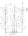
- the structure of a multi-user detector according to a first embodiment of the invention is illustrated in Fig 5.
- the multi-user detector comprises a filter 510 matched to the signatures of the users and to the response(s) of the propagation channel(s) (the plural stands for the uplink).
- the filter 510 multiplies the vector r ( i ) of the frequency components by the matrix D ⁇ C H ( i ) in order to output the observation vector y ( i ) according to equation (11).
- the detector comprises also an equalisation filter 520 and an interference reconstruction filter 550.
- the equalisation filter performs a multiplication of the observation vector y ( i ) by a matrix F ( i ) and outputs a vector denoted ( i ).
- the components of the vector ( i ) are then subjected to hard decision in the detector 540 which outputs a vector b and (1) ( i ) of the estimated symbols for the K users (superscript 1 stands for the first stage).
- the vector of estimated symbols is subjected to a multiplication by a matrix B ( i ) in the filter 550.
- the symbols of or for the different users are then estimated from the new observation vector y (2) ( i ) in the hard decision detector 560.
- the vector of the estimates at the second detection stage is denoted b and (2) ( i ) .
- the estimated symbols are then demodulated into bits (whereby the symbols -1,1 are respectively transformed into 0,1 if BPSK modulation is used) and the obtained bits are subsequently channel decoded. Alternatively, if BPSK modulation is used, channel decoding may take place prior to demodulation.
- F ( i ) depends upon the criterion used for the equalisation.
- the parallel interference cancellation scheme can therefore be performed entirely at the symbol level. This significantly reduces the complexity of implementation, especially when the number of active users K is lower than the number of carriers L in the OFDM multiplex.
- a multi-user detector according to a second embodiment of the invention is illustrated in Fig. 6.
- the blocks 610, 620 and 650 are respectively identical to blocks 510, 520 and 550 of Fig. 5.
- the multi-user detector has been illustrated for a BPSK modulation, although other types of modulation may be used.
- the user data is subjected to channel coding prior to spreading in the frequency domain, at the transmitter side. Furthermore, as known to the man skilled in the art, interleaving steps may be inserted prior to or/and after channel coding.
- the conventional methods of block coding, convolutional coding or turbo-coding can be used for channel coding.
- Each of these decoders performs a channel decoding of the data for one of the K active users. More precisely, decoder 640 k inputs soft values ( i ) and outputs channel decoded data for user k , denoted d and (1) / k ( i ).
- the channel decoded data for the K users are represented by vector d and (1) ( i ).
- the decoder 640 k is a Viterbi decoder
- the decoder 640 k is able to supply the channel decoded data and the data in the channel encoded form along the maximum likelihood path in the code trellis.
- the new observation vector y (2) ( i ) cleared form MAI is subjected to channel decoding in the decoders 641 1 ,..,641 K similar to decoders 640 1 ,..,640 K to output channel decoded data d and (2) / k ( i ) for the K users.
- the channel decoded data for the K users at the second stage are represented by vector d and (2) ( i ).
- deinterleavers and interleavers have to be provided before the channel decoders 640 1 ,..,640 K and after the channel encoders 670 1 ,.., 670 K , respectively.
- the decoders 640 1 ,..,640 K and 641 1 ,..,641 K can be realised by a SISO (soft-in soft-out) decoder followed by a thresholder.
- SISO soft-in soft-out
- a multi-user detector according to a third embodiment of the invention is illustrated in Fig 7.
- the blocks 710, 720 and 750 are respectively identical to blocks 510, 520 and 550 of Fig. 5.
- the multi-user detector has been illustrated for a BPSK modulation, although other types of modulation may be used.
- This embodiment makes use of SISO (soft-in soft-out) decoders 740 1 ,..,740 K which can be SOVA (Soft-Output Viterbi Algorithm) decoders or belong to the family of the MAP (Maximum A Priori) decoders.
- the decoder 740 k is adapted to supply both the channel decoded data d and (1) / k ( i ) and the corresponding data in channel encoded form b and (1) / k ( i ) for user k.
- the decoder 740 k outputs both the channel decoded data and the corresponding data in channel encoded form along the maximum likelihood path in the code trellis.
- MAP decoders can also output both a posteriori channel decoded data and corresponding data in channel encoded form as described in the article from S. Benedetto et al. entitled Soft-input soft-output modules for the construction and distributed iterative decoding of code networks published in European Transactions on Telecommunications, Vol. 9, N°2, March-April 1998.
- the decoded data for the K users are denoted as a vector d and (1) ( i ) while the data in encoded form for the K users are denoted as a vector b and (1) ( i ).
- the data in encoded form is directly filtered by the interference reconstruction filter 750 .
- channel encoders are no longer needed, thus further reducing the complexity of the receiver.
- the new observation vector y (2) ( i ) cleared form MAI, is submitted to soft channel decoding in the SISO decoders 741 1 ,..,741 K .
- the soft outputs d and (2) / k ( i ) represented as vector d and (2) ( i ) are then thresholded in hard decision module 760 to give the channel decoded data of the K active users, represented as a vector d and (2) ( i ) of components d and (2) / k ( i ), where d and (2) / k ( i ) is the channel decoded data for the user k .
- multi-user detection device for an MC-CDMA receiver has been described in terms of functional modules e.g. filters or estimating means, it goes without saying that all or parts of this device can be implemented by means of a single processor either dedicated for fulfilling all the functions depicted or in the form of a plurality of processors either dedicated or programmed for each fulfilling one or some of said functions.
Landscapes
- Engineering & Computer Science (AREA)
- Signal Processing (AREA)
- Computer Networks & Wireless Communication (AREA)
- Cable Transmission Systems, Equalization Of Radio And Reduction Of Echo (AREA)
- Noise Elimination (AREA)
Abstract
said frequency components are subjected to a first filtering (510,610,710) matched to the respective signatures of a second plurality (K) of users and to the common or the respective responses of the transmission channels associated to said communications to or from said users;
a first estimation (540,640 k ,740 k ) of the symbols transmitted to or by said users is obtained from the output of said first filtering;
a multi-user interference is derived (550,650,750) from said first estimation and subtracted (530,630,730) from the output of said first filtering to provide a cleared output;
a second estimation (560,641 k ,660, 741 k ,760) of the symbols transmitted to or by said users is obtained from said cleared output.
Description
- The present invention relates to a multi-user detection method for a receiver in a multi-carrier code division multiple access system and more specifically to a multi-user detection method with parallel interference cancellation. The present invention concerns also a MC-CDMA receiver implementing such a parallel interference cancellation.
- Multi-Carrier Code Division Multiple Access (MC-CDMA) combines OFDM (Orthogonal Frequency Division Multiplex) modulation and the CDMA multiple access technique. This multiple access technique was proposed for the first time by N. Yee et al. in the article entitled "Multicarrier CDMA in indoor wireless radio networks" which appeared in Proceedings of PIMRC'93, Vol. 1, pages 109-113, 1993. The developments of this technique were reviewed by S. Hara et al. in the article entitled "Overview of Multicarrier CDMA" published in IEEE Communication Magazine, pages 126-133, December 1997.
- Unlike the DS-CDMA (Direct Sequence Code Division Multiple Access) method, in which the signal of each user is multiplied in the time domain in order to spread its frequency spectrum, the signature here multiplies the signal in the frequency domain, each element of the signature multiplying the signal of a different sub-carrier.
- More precisely, Fig. 1 shows the structure of an MC-CDMA transmitter for a given user k. Let bk (i) be the i th symbol to be transmitted from the user k, where bk (i) belongs to the modulation alphabet. The symbol bk (i) is first of all multiplied at 110 by a spreading sequence or signature of the user, denoted ck (t), consisting of N "chips", each "chip" being of duration Tc , the total duration of the spreading sequence corresponding to a symbol period T. The results of the multiplication of the symbol bk (i) by the different "chips" are converted by the serial to
parallel converter 120 into a block of L symbols, where L is in general a multiple of N. It will be considered, for reasons of simplification of presentation, that L=N. The block of L symbols is then subjected to an inverse fast Fourier transformation (IFFT) in themodule 130. In order to prevent intersymbol interference, a guard interval, with a length greater than the duration of the pulse-type response of the transmission channel, is added to the MC-CDMA symbol. This interval is obtained by appending a suffix (denoted Δ) identical to the start of the said symbol. After parallel to serial conversion in 140, the MC-CDMA symbols thus obtained are amplified at 150 in order to be transmitted over the user channel. It can therefore be seen that the MC-CDMA method can be analysed into a spreading in the spectral domain (before IFFT) followed by an OFDM modulation. - In practice, a user k transmits his data in the form of frames of I symbols, each symbol bk (i) being spread by a real signature ck (t), typically a Walsh-Hadamard signature, with a duration equal to the symbol period T, such that ck (t)=0 if t∉[0,T[. The signal modulated at time t = (i - 1).T + (ℓ - 1).Tc can then be written, if the guard intervals between MC-CDMA symbols are omitted:where ωk is the amplitude of the signal transmitted by the user k, assumed to be constant over a transmission unit.

- An MC-CDMA receiver for a given user k has been illustrated schematically in Fig. 2. This receiver is known as single-user detection receiver (or SUD receiver) because the detection takes only into account the symbols transmitted to (or from) the user in question.
- The demodulated received signal is sampled at the "chip" frequency. The signal thus obtained can be written:where K is the number of users, ckℓ = ck ((ℓ - 1).Tc ), hkℓ (i) represents the response of the channel of the user k to the frequency of the subcarrier ℓ of the MC-CDMA symbol transmitted at time i.T and where n(t) is the received noise.

- If the downlink channel is considered, the transmission channels have identical characteristics and therefore hkℓ=hℓ.
- The samples obtained by sampling at the "chip" frequency are put in parallel in a serial to
parallel converter 210 and stripped from the suffix (Δ) before undergoing an FFT in themodule 220. - In MC-CDMA, the presence of the guard period makes it possible to neglect the intersymbol interference. For a given subcarrier (hereinafter simply called carrier), the equalisation can therefore be performed by a single tap, i.e. by a multiplication by a complex coefficient. In the SUD receiver, the equalisation is performed carrier-by-carrier i.e. by applying one of the known equalisation methods: MRC (Maximum Ratio Combining), EGC (Equal Gain Combining), ZF (Zero Forcing) or MMSE (Minimum Mean Square Error) independently on each carrier. The equalising coefficients thus obtained are denoted qk, 1,.., qk,L on Fig. 2.
- The samples in the frequency domain, output from 220, are multiplied by the equalising coefficients and the signature of the user k in 2400,..,240 L -1 (for despreading) before being added in 250. The result is a soft estimate bk (i) of the transmitted symbol bk (i). The soft estimate is then subjected to a hard decision in the
hard decision module 260 to output an estimate b andk (i) belonging to the modulation alphabet. - The multiuser detection techniques are known notably in CDMA telecommunications systems. They have the common characteristic of taking account of the interference generated by the other users.
- A multiuser detection or MUD technique for MC-CDMA was presented in the article by J-Y. Beaudais, J.F. Hélard and J. Citerne entitled "A novel linear MMSE detection technique for MC-CDMA" published in Electronics Letters, Vol. 36, N°7, pages 665-666, 30 March 2000. The equalisation method proposed no longer operates carrier by carrier but MC-CDMA symbol by MC-CDMA symbol, taking account of all the carriers and all the signatures of the active users. For this reason it is called GMMSE (Global Minimum Mean Square Error) equalisation or, equivalently, M-MMSE (Matrix Minimum Mean Square Error) equalisation. Its purpose is to minimise the mean square error between the soft estimated symbols b andk (i) and the transmitted symbols bk (i). The soft estimate is then subjected to a hard decision in the
hard decision module 360. - An MC-CDMA receiver with GMMSE equalisation for a user k has been shown in Fig. 3. Its structure differs from that of Fig. 2 in that the equalisation is effected by means of a
multiplication 330 by a matrix Q of the signals of the different carriers. The despread signal obtained at the output of theadder 350 gives a soft estimate b andk (i) of the transmitted symbol bk (i). - Furthermore, there have been proposed MC-CDMA receivers using either a parallel interference cancellation (PIC) scheme or a serial interference cancellation scheme (SIC), as disclosed in the article by J-Y. Beaudais et al. Parallel interference cancellation consists in iteratively cancelling the multiple access interference (MAI) by subtracting for a given user the contributions due to the other users, these contributions being obtained, for a given step, by respreading the symbols estimated at the previous step and filtering them with filters modelling the transmission channels over which they have propagated. In contrast, serial interference cancellation consists in successively eliminating the contributions of the users in a cascade of stages, each stage eliminating the contribution of a particular user, commencing by the contribution of highest power.
- Fig. 4 illustrates the structure of a MC-CDMA receiver with parallel interference cancellation. For the sake of clarity, only the part related to a user k has been represented. In Fig. 4, r(i) denotes the output of the FFT, i.e. the vector of frequency components supplied by
stage 320 in Fig. 3 at time i.T. These components are subjected to a first equalisation in 410. More precisely, 410 provides for an equalisation for the K-1 transmission channels associated with the users k'=1,..K, k'≠ k. If we consider the downlink receiver, the transmission channels are identical, theequalisation 410 amounts to a simple multiplication by an LxL matrix and the output is a vector of dimension L. In the uplink receiver however, K-1 matrices are involved, each matrix corresponding to a transmission channel of a user. These K-1 matrices are represented by the tensor, where the index (1) stands for the first cancellation stage. After equalisation, the received MC-CDMA symbols are despread in 420 with the K-1 signatures of the users k'=1,..K, k'≠ k. and detected in 430. This first estimation does not take into account the MAI. The detected symbols are then respread by said signatures in 440 and the MC-CDMA symbols thus obtained are filtered by K-1 filters modelling the transmission channels of the users k'. Each filter can be represented by an LxL diagonal matrix and the K-1 matrices are represented by the tensor . Here again, if the downlink receiver is considered, the latter matrices are identical. In any case, the K-1 outputs of 450 give the respective contributions of the users k' to the MAI. They are subtracted from r(i) (delayed so as to compensate for the processing time in 410-450) in 4601,.., 460 K -1. The output of 460 K -1 is a version of r(i) freed of a first estimation of MAI. The process can be repeated so as to refine the estimation of the MAI and jointly improve the detection of the symbols. The last stage is followed by a classical single-user equalisation in 470, despreading in 480 and symbol detection in 490 as in Fig. 2.
- The proposed parallel and serial cancellation schemes in MC-CDMA are rather complex in particular for the uplink receiver since some processing stages are performed at the carrier level and therefore involve (K-1).L operations in parallel where K is the number of users and L is the number of carriers.
- The object of the present invention is to propose a MC-CDMA receiver with multi-user detection and MAI removal which is simpler than those known from the prior art. In particular, the object of the invention is to propose a MC-CDMA receiver of said type which is simpler when the number of users is low.
- The above mentioned object is attained by a multi-user detection method as claimed in appended
claim 1 and a multi-user receiver as claimed in independent claim 13. Further advantages are given by the technical features recited in the dependent claims. - The characteristics of the invention mentioned above, as well as others, will emerge more clearly from a reading of the following description given in relation to the accompanying figures, amongst which:
- Fig. 1 depicts schematically the structure of an MC-CDMA transmitter known from the state of the art;
- Fig. 2 depicts schematically the structure of a first MC-CDMA receiver known from the state of the art;
- Fig. 3 depicts schematically the structure of a second MC-CDMA receiver known from the state of the art;
- Fig. 4 depicts schematically the structure of an MC-CDMA receiver with parallel interference cancellation as known from the state of the art;
- Fig. 5 depicts schematically the structure of a MC-CDMA receiver with parallel interference cancellation according to a first embodiment of the invention;
- Fig. 6 depicts schematically the structure of a MC-CDMA receiver with parallel interference cancellation according to a second embodiment of the invention;
- Fig. 7 depicts schematically the structure of a MC-CDMA receiver with parallel interference cancellation according to a third embodiment of the invention.
-
- Once again the context of a MC-CDMA receiver with K users will be referred to. The L frequency components output by the FFT at time i can be regarded as a vector r(i) = ( r 1 (i),..., rL (i)) T , the expression of which can be derived from (2):is a matrix combining the effect of spreading and of channel propagation.

- In the downlink, all the users share the same channel and the matrix C(i) can be expressed by C(i)=H(i)C D where H(i)=diag(h 1(i),...,hL (i)) and C D is the LxK matrix containing the codes of the active users:

- If we assume that the components of the noise η(i) are AWGN (Additive White Gaussian Noise) with covariance matrix E[η(i)η H (i)]=N 0 I L where I L is the LxL identity matrix and N0 the noise variance, the maximum likelihood detection of the transmitted signal consists in finding the symbol b which minimises the quadratic distance d 2 Emin(b) between the received signal and the signal expected to be received if b was transmitted. Hence, from (3), said symbol b should minimise :
b - Equivalently, since r(i) is known, said symbol b should minimise the expression:
 the output of a filter matched to the signature of the user k and the propagation channel. yk (i) may also be viewed as the Maximum Ratio Combining of the components rℓ (i) of the received vector r(i), for user k. Equation (8) can be simply reformulated:

- Let us denote y(i)=(y 1(i),...,yK (i)) T the observation vector of the outputs yk (i) for the K users. According to (7) and (10), the vector y(i) represents a sufficient statistic for the maximum likelihood detection of the transmitted vector b(i).
- It is important to note, that using y(i) instead of r(i) for the multi-user detection advantageously reduces the observation dimension from L to K. The observation vector y(i) may be written in a matrix form from equation (9):
- It has been described in French patent application FR0104050 filed by the Applicant on 22.03.2001 and included herein by reference a multi-user detection method based on Wiener filtering of the observation vector y(i). According to this method, the vector of the estimated symbols
- By replacing (12) and (13) into (16) and assuming that symbols have a unit energy:
- The operation (14) can be regarded as an MMSE (Minimum Mean Square Error) equalisation process using the matrix F.
- Now, the basic idea underlying the invention is to propose a multi-user detection method with parallel interference cancellation at the symbol level and not at the carrier level as in the prior art set out in the introductive part.
- The structure of a multi-user detector according to a first embodiment of the invention is illustrated in Fig 5. The multi-user detector comprises a
filter 510 matched to the signatures of the users and to the response(s) of the propagation channel(s) (the plural stands for the uplink). Thefilter 510 multiplies the vector r(i) of the frequency components by the matrix D ω C H (i) in order to output the observation vector y(i) according to equation (11). The detector comprises also anequalisation filter 520 and aninterference reconstruction filter 550. The equalisation filter performs a multiplication of the observation vector y(i) by a matrix F(i) and outputs a vector denoted(i). The components of the vector
detector 540 which outputs a vector b and (1)(i) of the estimated symbols for the K users (superscript 1 stands for the first stage). The vector of estimated symbols is subjected to a multiplication by a matrix B(i) in thefilter 550. The output of thesecond filter 550 is subtracted in 530 from the output of the matchedfilter 510 to provide a new observation vector y (2)(i) (where superscript 2 stands for the second detection stage):hard decision detector 560. The vector of the estimates at the second detection stage is denoted b and (2) ( i ). The estimated symbols are then demodulated into bits (whereby the symbols -1,1 are respectively transformed into 0,1 if BPSK modulation is used) and the obtained bits are subsequently channel decoded. Alternatively, if BPSK modulation is used, channel decoding may take place prior to demodulation. - The matrix F(i) depends upon the criterion used for the equalisation. For an equalisation of the MMSE type, F(i) is given by equation (17), i.e.
- Alternatively, for an equalisation based on the Zero Forcing (ZF) criterion, the matrix F(i) is simply given by:
- It should be noted that, instead of multiplying y(i) by the matrix F(i) for obtaining
- Recalling that the component of the observation vector for user k isif we have an estimate b and (1)(i) of the K transmitted symbols, we can derive a new component which is cleared from MAI:
 where the expression between square brackets gives the received signal on subcarrier ℓ cleared from the contribution of the other users k'≠k.
- Expression (20) can be reformulated as follows:which can be rewritten in a matrix form:

- The parallel interference cancellation scheme can therefore be performed entirely at the symbol level. This significantly reduces the complexity of implementation, especially when the number of active users K is lower than the number of carriers L in the OFDM multiplex.
- The structure of a multi-user detector according to a second embodiment of the invention is illustrated in Fig. 6. The
blocks blocks - In this embodiment, the user data is subjected to channel coding prior to spreading in the frequency domain, at the transmitter side. Furthermore, as known to the man skilled in the art, interleaving steps may be inserted prior to or/and after channel coding. The conventional methods of block coding, convolutional coding or turbo-coding can be used for channel coding.
- In contrast with the previous embodiment, there are provided
K channel decoders 6401,..,640 K after theequalisation filter 620, for the K active users, respectively. Each of these decoders performs a channel decoding of the data for one of the K active users. More precisely,decoder 640 k inputs soft values(i) and outputs channel decoded data for user k, denoted d and (1) / k(i). The channel decoded data for the K users are represented by vector d and (1)(i). The estimated data d and (1) / k(i), k=1,..,K are then respectively reencoded by the
channel encoders 670 k , k=1,..,K before being filtered by theinterference reconstruction filter 650. Alternatively, if thedecoders 640 k , k=1,..,K are able to supply the estimated data in encoded form, thechannel encoders 670 k , k=1,..,K will be omitted and the estimated data in encoded form will be supplied directly to theinterference reconstruction filter 650. For example, if thedecoder 640 k , is a Viterbi decoder, thedecoder 640 k is able to supply the channel decoded data and the data in the channel encoded form along the maximum likelihood path in the code trellis. - After interference cancellation in 630, the new observation vector y (2)(i) cleared form MAI is subjected to channel decoding in the decoders 6411,..,641 K similar to
decoders 6401,..,640 K to output channel decoded data d and (2) / k(i) for the K users. The channel decoded data for the K users at the second stage are represented by vector d and (2)(i). Of course, if the user data are interleaved at the transmitter side, e.g. after channel coding, deinterleavers and interleavers have to be provided before thechannel decoders 6401,..,640 K and after thechannel encoders 6701,.., 670 K , respectively. - It should be understood that the data output from the channel encoders 670 k k=1,..,K have to be modulated into symbols prior to the filtering by the
interference reconstruction filter 650. - In this embodiment, it should also be understood that the
decoders 6401,..,640 K and 6411,..,641 K can be realised by a SISO (soft-in soft-out) decoder followed by a thresholder. - The structure of a multi-user detector according to a third embodiment of the invention is illustrated in Fig 7. The
blocks blocks - This embodiment makes use of SISO (soft-in soft-out)
decoders 7401,..,740 K which can be SOVA (Soft-Output Viterbi Algorithm) decoders or belong to the family of the MAP (Maximum A Priori) decoders. In both cases, thedecoder 740 k is adapted to supply both the channel decoded data d and (1) / k(i) and the corresponding data in channel encoded form b and (1) / k(i) for user k. For example, if SOVA decoders are used, thedecoder 740 k outputs both the channel decoded data and the corresponding data in channel encoded form along the maximum likelihood path in the code trellis. MAP decoders can also output both a posteriori channel decoded data and corresponding data in channel encoded form as described in the article from S. Benedetto et al. entitled Soft-input soft-output modules for the construction and distributed iterative decoding of code networks published in European Transactions on Telecommunications, Vol. 9, N°2, March-April 1998. - The decoded data for the K users are denoted as a vector d and (1) (i) while the data in encoded form for the K users are denoted as a vector b and (1)(i). The data in encoded form is directly filtered by the
interference reconstruction filter 750 . In contrast with the previous embodiment, channel encoders are no longer needed, thus further reducing the complexity of the receiver. After interference cancellation in 730, the new observation vector y (2)(i), cleared form MAI, is submitted to soft channel decoding in theSISO decoders 7411,..,741 K. The soft outputs d and (2) / k(i) represented as vector d and (2)(i) are then thresholded inhard decision module 760 to give the channel decoded data of the K active users, represented as a vector d and (2)(i) of components d and (2) / k(i), where d and (2) / k(i) is the channel decoded data for the user k. Here again, if a modulation other than BPSK is used, the data in channel encoded form, output from thechannel encoders 740 k , k=1,..,K and represented by vector b and (1)(i), have to be modulated into symbols prior to the filtering by theinterference reconstruction filter 750. - It is important to note that the embodiments of the invention described above apply equally to downlink and uplink MC-CDMA receivers.
- Furthermore, although the multi-user detection device for an MC-CDMA receiver according to the invention has been described in terms of functional modules e.g. filters or estimating means, it goes without saying that all or parts of this device can be implemented by means of a single processor either dedicated for fulfilling all the functions depicted or in the form of a plurality of processors either dedicated or programmed for each fulfilling one or some of said functions.
Claims (13)
- Multi-user detection method for a receiver in a multi-carrier code division multiple access telecommunication system, each communication to or from a user of the system being coded with a signature, the signal received by said receiver being decomposed into a first plurality (L) of frequency components,
characterised in that
said frequency components are subjected to a first filtering (510,610,710) matched to the respective signatures of a second plurality (K) of users and to the common or the respective responses of the transmission channels associated to said communications to or from said users;
a first estimation (540,640 k ,740 k ) of symbols or data transmitted to or by said users is obtained from the output of said first filtering;
a multi-user interference is derived (550,650,750) from said first estimation and subtracted (530,630,730) from the output of said first filtering to provide a cleared output;
a second estimation (560,641 k ,660,741 k ,760) of the symbols or data transmitted to or by said users is obtained from said cleared output. - Multi-user detection method according to claim 1, characterised in that the output of said first filtering is subjected to an equalisation step (520,620,720) prior to said first estimation.
- Multi-user detection method according to claim 2, characterised in that the equalisation step uses a Minimum Mean Square Error equalisation.
- Multi-user detection method according to claim 2, characterised in that the equalisation step uses a Zero Forcing equalisation.
- Multi-user detection method according to any of claims 2 to 4, characterised in that said first estimation provides first estimates (b and (1) / k(i)) of the symbols transmitted to or by said users by applying a hard decision (540) on the equalised output of said first filtering and said second estimation subsequently provides second estimates (b and (2) / k(i)) of said symbols by applying a hard decision (560) to said cleared output.
- Multi-user detection method according to claim 5, characterised in that said second filtering (550) is applied to said first estimates (b and (1) / k(i)) and that said cleared output is obtained by subtracting (530) the output of said second filtering (550) from the output of said first filtering (510).
- Multi-user detection method according to any of claims 2 to 4, characterised in that said first estimation applies a first channel decoding step (6401,..,640 K ) to the equalised output of said first filtering for providing first estimates (d and (1) / k(i)) of data transmitted to or by said users and that said second estimation applies a second channel decoding step (6411,..,641 K ) to said cleared output for providing second estimates (d and (2) / k(i)) of said data.
- Multi-user detection method according to claim 7, characterised in that said first estimates are further subjected to a channel coding step (6701,..,670 K ) followed by a second filtering (650), said cleared output being obtained by subtracting (630) the output of said second filtering (650) from the output of said first filtering (610).
- Multi-user detection method according to claim 7, characterised in that said first estimates are supplied in channel encoded form to a second filtering, said cleared output being obtained by subtracting (630) the output of said second filtering (650) from the output of said first filtering (610).
- Multi-user detection method according to any of claims 2 to 4, characterised in that said first estimation applies a soft-in soft-out channel decoding step (7401,..,740 K ) to the equalised output of said filtering for providing both first estimates (d and (1) / k(i)) of data transmitted to or by said users and corresponding data in channel encoded form.
- Multi-user detection method according to claim 10, characterised in that a second filtering (750) is applied to said data in channel encoded form, said cleared output being obtained by subtracting (730) the output of said second filtering (750) from the output of said first filtering (710).
- Multi-user detection method according to one of claims 6,8,11, characterised in that said second filtering comprises a multiplication step by a matrix B(i) = R(i) - diag(R(i)) where R(i) is the autocovariance matrix of the output of said first filtering and diag(R(i)) is a matrix having the same diagonal elements as R(i) and zero off-diagonal elements.
- Multi-user receiver for a multi-carrier code division multiple access telecommunication system, characterised by comprising means for carrying out the multi-user detection method according to any of claims 1 to 12.
Priority Applications (3)
| Application Number | Priority Date | Filing Date | Title |
|---|---|---|---|
| EP01123755A EP1300977A1 (en) | 2001-10-04 | 2001-10-04 | Parallel interference cancellation in an MC-CDMA telecommunication system |
| JP2002263055A JP4284047B2 (en) | 2001-10-04 | 2002-09-09 | Multi-user detection method for receiver of multi-carrier code division multiple access communication system |
| US10/238,719 US7286517B2 (en) | 2001-10-04 | 2002-09-11 | Multi-user detection method for a receiver in a MC-CDMA telecommunication system |
Applications Claiming Priority (1)
| Application Number | Priority Date | Filing Date | Title |
|---|---|---|---|
| EP01123755A EP1300977A1 (en) | 2001-10-04 | 2001-10-04 | Parallel interference cancellation in an MC-CDMA telecommunication system |
Publications (1)
| Publication Number | Publication Date |
|---|---|
| EP1300977A1 true EP1300977A1 (en) | 2003-04-09 |
Family
ID=8178847
Family Applications (1)
| Application Number | Title | Priority Date | Filing Date |
|---|---|---|---|
| EP01123755A Withdrawn EP1300977A1 (en) | 2001-10-04 | 2001-10-04 | Parallel interference cancellation in an MC-CDMA telecommunication system |
Country Status (3)
| Country | Link |
|---|---|
| US (1) | US7286517B2 (en) |
| EP (1) | EP1300977A1 (en) |
| JP (1) | JP4284047B2 (en) |
Cited By (3)
| Publication number | Priority date | Publication date | Assignee | Title |
|---|---|---|---|---|
| WO2004107623A1 (en) * | 2003-06-02 | 2004-12-09 | Matsushita Electric Industrial Co., Ltd. | Radio communication system and radio communication method |
| EP1618681A4 (en) * | 2003-05-01 | 2007-05-30 | Nokia Corp | METHOD AND APPARATUS FOR INCREASING THE DATA RATE IN A BROADBAND MC-CDMA TELECOMMUNICATION SYSTEM |
| CN105407063A (en) * | 2014-09-10 | 2016-03-16 | 三星电子株式会社 | Apparatus and method for mitigating interference in a wireless communication system |
Families Citing this family (16)
| Publication number | Priority date | Publication date | Assignee | Title |
|---|---|---|---|---|
| FR2822567B1 (en) * | 2001-03-22 | 2003-05-02 | Mitsubishi Electric Inf Tech | GMMSE TYPE EQUALIZATION METHOD AND DEVICE |
| ATE283580T1 (en) * | 2001-07-05 | 2004-12-15 | Mitsubishi Electric Inf Tech | MULTI-USER DETECTION IN A MC-CDMA TELECOMMUNICATIONS SYSTEM |
| US7079828B1 (en) * | 2002-10-25 | 2006-07-18 | Edgewater Computer Systems, Inc. | Method and apparatus for side-lobe cancellation in wideband radio systems |
| US7042967B2 (en) * | 2003-03-03 | 2006-05-09 | Interdigital Technology Corporation | Reduced complexity sliding window based equalizer |
| TWI260143B (en) * | 2003-03-03 | 2006-08-11 | Interdigital Tech Corp | Reduced complexity sliding window based equalizer method and apparatus |
| AU2003251738A1 (en) * | 2003-04-24 | 2004-11-26 | Bae Systems Information And Electronic Systems Integration, Inc. | Cross-system interference cancellation for multicarrier cdma and ofdm |
| US7590199B2 (en) * | 2003-09-12 | 2009-09-15 | Advantech Advanced Microwave Technologies Inc. | Hybrid frequency offset estimator |
| US7428260B2 (en) | 2003-10-30 | 2008-09-23 | Marvell World Trade Ltd. | Unified MMSE equalization and multi-user detection approach for use in a CDMA system |
| FR2863122B1 (en) * | 2003-11-28 | 2006-04-28 | Thales Sa | METHOD AND APPARATUS FOR INCREASING THE CAPACITY OF NON-ETAL TRANSMISSION SYSTEMS |
| US7593473B2 (en) * | 2004-12-01 | 2009-09-22 | Bae Systems Information And Electronic Systems Integration Inc. | Tree structured multicarrier multiple access systems |
| US8670493B2 (en) | 2005-06-22 | 2014-03-11 | Eices Research, Inc. | Systems and/or methods of increased privacy wireless communications |
| US7881410B2 (en) | 2005-06-29 | 2011-02-01 | Samsung Electronics Co., Ltd. | Apparatus and method for detecting user in a communication system |
| KR101329145B1 (en) * | 2007-10-05 | 2013-11-21 | 포항공과대학교 산학협력단 | Method of space block coding signal transmission and receive with interactive multiuser detection, and aparatus using the same |
| TWI429207B (en) * | 2009-06-21 | 2014-03-01 | Ablaze Wireless Inc | Transform domain multi-user detection and interference suppression apparatus for femtocell |
| US8385387B2 (en) * | 2010-05-20 | 2013-02-26 | Harris Corporation | Time dependent equalization of frequency domain spread orthogonal frequency division multiplexing using decision feedback equalization |
| CN105635025B (en) * | 2016-01-26 | 2018-09-07 | 哈尔滨工业大学 | Multi-user's mixed carrier method of NOMA uplinks |
Family Cites Families (18)
| Publication number | Priority date | Publication date | Assignee | Title |
|---|---|---|---|---|
| US5377225A (en) * | 1993-10-19 | 1994-12-27 | Hughes Aircraft Company | Multiple-access noise rejection filter for a DS-CDMA system |
| BR9408527A (en) * | 1994-02-10 | 1997-08-05 | Ibm | Method and apparatus for reducing the interference of input signals produced by multiple users in communication systems and cdma communication system that use them |
| US6201799B1 (en) * | 1997-05-01 | 2001-03-13 | Lucent Technologies, Inc | Partial decorrelation for a coherent multicode code division multiple access receiver |
| US6075792A (en) * | 1997-06-16 | 2000-06-13 | Interdigital Technology Corporation | CDMA communication system which selectively allocates bandwidth upon demand |
| SG77607A1 (en) * | 1997-08-26 | 2001-01-16 | Univ Singapore | A multi-user code division multiple access receiver |
| US6175588B1 (en) * | 1997-12-30 | 2001-01-16 | Motorola, Inc. | Communication device and method for interference suppression using adaptive equalization in a spread spectrum communication system |
| US6301293B1 (en) * | 1998-08-04 | 2001-10-09 | Agere Systems Guardian Corp. | Detectors for CDMA systems |
| JP2000082982A (en) * | 1998-09-03 | 2000-03-21 | Nec Corp | Array antenna reception device |
| AU2273099A (en) * | 1998-12-15 | 2000-07-03 | Nokia Networks Oy | A receiver |
| US6151358A (en) * | 1999-08-11 | 2000-11-21 | Motorola, Inc. | Method and apparatus, and computer program for producing filter coefficients for equalizers |
| US6714527B2 (en) * | 1999-09-21 | 2004-03-30 | Interdigital Techology Corporation | Multiuser detector for variable spreading factors |
| US6614836B1 (en) * | 2000-01-28 | 2003-09-02 | Intersil Americas Inc. | Biased-corrected rake receiver for direct sequence spread spectrum waveform |
| US6654408B1 (en) * | 2000-10-27 | 2003-11-25 | Wisconsin Alumni Research Foundation | Method and system for multi-carrier multiple access reception in the presence of imperfections |
| JP3639206B2 (en) * | 2000-11-24 | 2005-04-20 | 富士通株式会社 | Parallel matrix processing method and recording medium in shared memory type scalar parallel computer |
| US6711219B2 (en) * | 2000-12-04 | 2004-03-23 | Tensorcomm, Incorporated | Interference cancellation in a signal |
| FR2822568B1 (en) * | 2001-03-22 | 2003-06-06 | Mitsubishi Electric Inf Tech | GMMSE TYPE EQUALIZATION METHOD AND DEVICE |
| US6785341B2 (en) * | 2001-05-11 | 2004-08-31 | Qualcomm Incorporated | Method and apparatus for processing data in a multiple-input multiple-output (MIMO) communication system utilizing channel state information |
| ATE283580T1 (en) * | 2001-07-05 | 2004-12-15 | Mitsubishi Electric Inf Tech | MULTI-USER DETECTION IN A MC-CDMA TELECOMMUNICATIONS SYSTEM |
-
2001
- 2001-10-04 EP EP01123755A patent/EP1300977A1/en not_active Withdrawn
-
2002
- 2002-09-09 JP JP2002263055A patent/JP4284047B2/en not_active Expired - Fee Related
- 2002-09-11 US US10/238,719 patent/US7286517B2/en not_active Expired - Fee Related
Non-Patent Citations (5)
| Title |
|---|
| BAUDAIS J-Y ET AL: "AN IMPROVED LINEAR MMSE DETECTION TECHNIQUE FOR MULTI-CARRIER CDMA SYSTEMS: COMPARISON AND COMBINATION WITH INTERFERENCE CANCELLATION SCHEMES", EUROPEAN TRANSACTIONS ON TELECOMMUNICATIONS, EUREL PUBLICATION, vol. 11, no. 6, 1 November 2000 (2000-11-01), Milano, IT, pages 547 - 554, XP001006826, ISSN: 1124-318X * |
| HEGARTY C ET AL: "TWO-STAGE MULTIUSER DETECTION FOR ASYNCHRONOUS CDMA USING DPSK SIGNALLING", GLOBAL TELECOMMUNICATIONS CONFERENCE, 18 November 1996 (1996-11-18), IEEE, New York, NY, USA, pages 132 - 136, XP000741701, ISBN: 0-7803-3337-3 * |
| KAFLE P L ET AL: "Performance of turbo coded multicarrier CDMA with iterative multiuser detection and decoding", CANADIAN CONFERENCE ON ELECTRICAL AND COMPUTER ENGINEERING 2001. CONFERENCE PROCEEDINGS (CAT. NO.01TH8555), vol. 1, 13 May 2001 (2001-05-13) - 16 May 2001 (2001-05-16), IEEE, Piscataway, NJ, USA, pages 105 - 110, XP002192399, ISBN: 0-7803-6715-4 * |
| KAISER S ET AL: "Multi-carrier CDMA with iterative decoding and soft-interference cancellation", GLOBAL TELECOMMUNICATIONS CONFERENCE, 3 November 1997 (1997-11-03) - 8 November 1997 (1997-11-08), IEEE, New York, NY, USA, pages 6 - 10, XP010254574, ISBN: 0-7803-4198-8 * |
| KIM D-J ET AL: "THE NEW APPROACH TO MITIGATE MAI IN MC-CDMA SYSTEMS", VEHICULAR TECHNOLOGY CONFERENCE, vol. 1, 19 September 1999 (1999-09-19) - 22 September 1999 (1999-09-22), IEEE, New York, USA, pages 171 - 175, XP000929034, ISBN: 0-7803-5436-2 * |
Cited By (6)
| Publication number | Priority date | Publication date | Assignee | Title |
|---|---|---|---|---|
| EP1618681A4 (en) * | 2003-05-01 | 2007-05-30 | Nokia Corp | METHOD AND APPARATUS FOR INCREASING THE DATA RATE IN A BROADBAND MC-CDMA TELECOMMUNICATION SYSTEM |
| US7286603B2 (en) | 2003-05-01 | 2007-10-23 | Nokia Corporation | Method and apparatus for increasing data rates in a wideband MC-CDMA telecommunication system |
| WO2004107623A1 (en) * | 2003-06-02 | 2004-12-09 | Matsushita Electric Industrial Co., Ltd. | Radio communication system and radio communication method |
| JP2004363721A (en) * | 2003-06-02 | 2004-12-24 | Matsushita Electric Ind Co Ltd | Wireless communication system and wireless communication method |
| CN105407063A (en) * | 2014-09-10 | 2016-03-16 | 三星电子株式会社 | Apparatus and method for mitigating interference in a wireless communication system |
| CN105407063B (en) * | 2014-09-10 | 2020-09-08 | 三星电子株式会社 | Apparatus and method for mitigating interference in a wireless communication system |
Also Published As
| Publication number | Publication date |
|---|---|
| JP2003188849A (en) | 2003-07-04 |
| US20030072291A1 (en) | 2003-04-17 |
| JP4284047B2 (en) | 2009-06-24 |
| US7286517B2 (en) | 2007-10-23 |
Similar Documents
| Publication | Publication Date | Title |
|---|---|---|
| US7286517B2 (en) | Multi-user detection method for a receiver in a MC-CDMA telecommunication system | |
| AU2007233563B2 (en) | Channel estimation for rapid dispersive fading channels | |
| El Gamal et al. | Iterative multiuser detection for coded CDMA signals in AWGN and fading channels | |
| US7463703B2 (en) | Joint symbol, amplitude, and rate estimator | |
| US7023265B1 (en) | Equalizing method in receivers using a combination of multiple carrier and code division multiple access modulating techniques | |
| KR100843253B1 (en) | Iterative reception method and Iterative receiver | |
| US20090141834A1 (en) | Receiver and receiving method for rf signals | |
| US20020041644A1 (en) | Multi-user detection method | |
| EP1603264B1 (en) | Method and system for receiving a linearly precoded and channel coded signal | |
| Kafle et al. | Iterative semiblind multiuser receivers for a space-time block-coded MC-CDMA uplink system | |
| EP1274176B1 (en) | Multi-user detection in an MC-CDMA telecommunication system | |
| Kafle et al. | Iterative semi-blind multiuser detection for coded MC-CDMA uplink system | |
| EP1359700A1 (en) | MC-CDMA receiver with an equalisation per subcarrier | |
| EP1661286B1 (en) | Receiver and method for decoding a coded signal with the aid of a space-time or space-frequency coding matrix | |
| EP1757051B1 (en) | Apparatus and method for iteratively estimating a channel transfer function | |
| US7333538B2 (en) | Equalisation method and device of the GMMSE type | |
| EP1276268B1 (en) | Multi-user detection in an MC-CDMA telecommunication system | |
| US7298801B2 (en) | Method and device for demodulating signals from multiple users | |
| Chang et al. | Cancellation of ICI by Doppler effect in OFDM systems | |
| Kafle et al. | Performance of turbo coded multicarrier CDMA with iterative multiuser detection and decoding | |
| Al-Iesawi | Iterative hybrid decision-feedback equalization (HDFE) based single-carrier IDMA schemes | |
| Nasser et al. | Sensitivity of multicarrier two-dimensional spreading schemes to synchronization errors | |
| Kafle et al. | An iterative semi-blind multiuser detector for coded MC-CDMA uplink | |
| Xu et al. | A M-ary biorthogonal code SS multicarrier CDMA transmission scheme | |
| Silva et al. | SIC and PIC multiuser detection for prefix-assisted DS-CDMA systems |
Legal Events
| Date | Code | Title | Description |
|---|---|---|---|
| PUAI | Public reference made under article 153(3) epc to a published international application that has entered the european phase |
Free format text: ORIGINAL CODE: 0009012 |
|
| AK | Designated contracting states |
Kind code of ref document: A1 Designated state(s): AT BE CH CY DE DK ES FI FR GB GR IE IT LI LU MC NL PT SE TR Designated state(s): AT BE CH CY DE DK ES FI FR GB GR IE IT LI LU MC NL PT SE TR |
|
| AX | Request for extension of the european patent |
Extension state: AL LT LV MK RO SI |
|
| 17P | Request for examination filed |
Effective date: 20030503 |
|
| 17Q | First examination report despatched |
Effective date: 20030807 |
|
| AKX | Designation fees paid |
Designated state(s): AT BE CH CY DE DK ES FI FR GB GR IE IT LI LU MC NL PT SE TR |
|
| RAP1 | Party data changed (applicant data changed or rights of an application transferred) |
Owner name: MITSUBISHI ELECTRIC R&D CENTRE EUROPE B.V. |
|
| STAA | Information on the status of an ep patent application or granted ep patent |
Free format text: STATUS: THE APPLICATION IS DEEMED TO BE WITHDRAWN |
|
| 18D | Application deemed to be withdrawn |
Effective date: 20150501 |