EP1300968A1 - A device for demultiplexing optical RZ signals - Google Patents
A device for demultiplexing optical RZ signals Download PDFInfo
- Publication number
- EP1300968A1 EP1300968A1 EP01440330A EP01440330A EP1300968A1 EP 1300968 A1 EP1300968 A1 EP 1300968A1 EP 01440330 A EP01440330 A EP 01440330A EP 01440330 A EP01440330 A EP 01440330A EP 1300968 A1 EP1300968 A1 EP 1300968A1
- Authority
- EP
- European Patent Office
- Prior art keywords
- signals
- shifted
- optical device
- filter
- pulses
- Prior art date
- Legal status (The legal status is an assumption and is not a legal conclusion. Google has not performed a legal analysis and makes no representation as to the accuracy of the status listed.)
- Withdrawn
Links
- 230000003287 optical effect Effects 0.000 title claims abstract description 26
- 230000005540 biological transmission Effects 0.000 claims abstract description 18
- 239000000835 fiber Substances 0.000 claims description 29
- 238000011144 upstream manufacturing Methods 0.000 claims description 3
- 238000001228 spectrum Methods 0.000 description 16
- 230000010287 polarization Effects 0.000 description 15
- 238000010586 diagram Methods 0.000 description 11
- 239000013307 optical fiber Substances 0.000 description 10
- 238000001514 detection method Methods 0.000 description 5
- 239000006185 dispersion Substances 0.000 description 3
- 230000001902 propagating effect Effects 0.000 description 3
- 238000011084 recovery Methods 0.000 description 3
- 230000005374 Kerr effect Effects 0.000 description 2
- 230000002159 abnormal effect Effects 0.000 description 1
- 230000000694 effects Effects 0.000 description 1
- 238000004519 manufacturing process Methods 0.000 description 1
- 238000000034 method Methods 0.000 description 1
- 230000008054 signal transmission Effects 0.000 description 1
- 230000003595 spectral effect Effects 0.000 description 1
Images

Classifications
-
- H—ELECTRICITY
- H04—ELECTRIC COMMUNICATION TECHNIQUE
- H04B—TRANSMISSION
- H04B10/00—Transmission systems employing electromagnetic waves other than radio-waves, e.g. infrared, visible or ultraviolet light, or employing corpuscular radiation, e.g. quantum communication
- H04B10/25—Arrangements specific to fibre transmission
- H04B10/2507—Arrangements specific to fibre transmission for the reduction or elimination of distortion or dispersion
- H04B10/25077—Arrangements specific to fibre transmission for the reduction or elimination of distortion or dispersion using soliton propagation
-
- H—ELECTRICITY
- H04—ELECTRIC COMMUNICATION TECHNIQUE
- H04J—MULTIPLEX COMMUNICATION
- H04J14/00—Optical multiplex systems
- H04J14/02—Wavelength-division multiplex systems
- H04J14/0223—Conversion to or from optical TDM
-
- H—ELECTRICITY
- H04—ELECTRIC COMMUNICATION TECHNIQUE
- H04J—MULTIPLEX COMMUNICATION
- H04J14/00—Optical multiplex systems
- H04J14/08—Time-division multiplex systems
Definitions
- the present invention relates to the field of optical fiber transmission. More particularly, it relates to return to zero (RZ) signal transmission systems such as transmission systems using soliton pulses of distinct intensities, for example.
- RZ return to zero
- WDM wavelength division multiplex
- the RZ signals are RZ pulses having distinct intensities.
- RZ pulses at a repetition rate of 10 GHz are coded in four levels of distinct intensities namely one zero level and three non-zero levels. This produces a train of pulses at 20 gigabits per second (Gbit/s) occupying a spectrum bandwidth that is about half the width corresponding to a conventional binary pulse train of two levels at 20 Gbit/s.
- Gbit/s gigabits per second
- An object of the invention is to provide an optical device for demultiplexing RZ optical signals of distinct intensities, in particular for high data rate optical fiber transmission systems that are simple to manufacture and operate.
- the invention provides an optical device for demultiplexing at least two RZ optical signals, each having a distinct non-zero intensity, said signals belonging to a given transmission channel having a given carrier frequency, and the device comprising:
- the device of the invention makes it possible to process the signals separately as a function of their intensities.
- the device of the invention enables three frequency-shifted signal trains to be extracted together, each train being at the repetition rate of 10 GHz, i.e. at a rate compatible with conventional detection systems.
- the device of the invention by incorporating the device of the invention in a high data transmission system, it is possible for the system to make use of high performance multilevel coding.
- the RZ signals of the invention can be soliton pulses.
- Known RZ signals include solitons which are generally transmitted in the portion of an optical fiber that presents abnormal dispersion.
- Solitons are pulses having a sech 2 hyperbolic secant waveform. With pulses of this waveform, the non-linearity in the corresponding portion of the fiber compensates for dispersion of the optical signal. Soliton transmission is modelled in conventional manner by the non-linear Schrödinger equation.
- Menyuk shows that above a certain power level, the Kerr effect leads to soliton pulses becoming stable in time by cross-phase modulation between the soliton components propagating with each of the two polarization directions. Mutual time trapping then takes place between the components with the two polarization directions; thus, above a certain intensity level, the components in both of the polarization directions travel together.
- the threshold intensity depends on the birefringence of the fiber.
- RZ signal can exist in which the components on the two polarization directions of a birefringent fiber become trapped by cross-phase modulation, in the same manner as for solitons.
- the means of the invention for spectrally shifting the signals can thus comprise a birefringent fiber.
- the birefringence of the fiber can be greater than or equal to 1 ⁇ 10 -5 .
- each signal of intensity greater than the threshold intensity is duplicated and thus presents two shifted carrier frequencies disposed symmetrically about the initial carrier frequency of the transmission channel.
- the spacing between the shifted carrier frequencies and the initial carrier frequency increases with increasing intensity of the signal.
- the two components of the shifted signal of the invention coincide in time at the outlet from the birefringent fiber.
- the signals that are injected into the birefringent fiber to be polarized in a direction that substantially bisects the two polarization directions of the fiber.
- the optical device of the invention preferably comprises means for polarizing the signals, which means are disposed at the inlet to the birefringent fiber.
- the means of the invention for extracting the shifted signals comprise a wavelength demultiplexer.
- the means for the invention for extracting the shifted signals comprise one discrete bandpass type filter per shifted signal, each filter being centered on a distinct "filter" frequency that is substantially equal to one or other of the two shifted carrier frequencies of the associated shifted signal.
- one-half of the half-height bandwidth of each filter can be less than the frequency spacing(s) between the filter frequency and the adjacent filter frequency(ies).
- the optical device of the invention can include means for amplifying the signals, which means can be located upstream from the shifting means.
- the spectrum shifting means comprise a birefringent fiber
- such an amplifier can serve to adjust the intensity of the signals to beyond the given threshold intensity.
- the invention proposes imparting differing spectrum shifts to the RZ signals as a function of their respective intensities, prior to extracting them individually.
- the invention proposes trapping signals propagating on the two polarization directions in a birefringent optical fiber. As mentioned above, such trapping occurs only above a certain intensity threshold.
- the invention applies in particular to soliton or to other RZ signals whose components on the polarization directions of a birefringent fiber can become trapped by cross-phase modulation, as is the case for solitons.
- Figure 1 is a diagram of a train S of four RZ signals in the form of pulses i 0 , i 1 , i 2 , i 3 transmitted in succession from left to right in the figure. Time is plotted along the abscissa, which is equivalent to length along a transmission system; and intensity is plotted up the ordinate.
- the first pulse i 0 referred to the zero level has zero intensity I 0 implemented by practically cutting off the signal source.
- the other three pulses i 1 , i 2 , i 3 referred to non-zero levels are of increasing non-zero intensities respectively equal to I 1 , I 2 , and I 3 .
- train S is also called multilevel signal.
- All of the pulses belong to a given transmission channel having a given carrier frequency.
- the transmission channel can form part of the C transmission band (1530 nanometers (nm) to 1560 nm) or the L band (1565 nm to 1610 nm).
- the repetition frequency of pulses is for example 10 GHz leading to a rate of 20 Gbit/s. Obviously, a higher rate is obtained by having a train pulse at higher repetition frequency and/or coding with more levels.
- Figure 2 is a diagram of a first embodiment of an optical demultiplexer device 100 of the invention which comprises in succession:
- a coupler 13 1 having two outlet branches a 1 and a 2 .
- One of the outlet branches a 1 in combination with clock recovery means 16 and the other a 2 leading to another coupler 13 2 having three outlet branches b 1 , b 2 , and b 3 .
- the dynamic behavior of the device 100 is described below with reference to the paths of the pulses i 0 , i 1 , i 2 , and i 3 .
- the pulses i 1 , i 2 , and i 3 are initially injected into the inlet of the device 100 via the amplifier 10 so that the pulses i 1 , i 2 , and i 3 present intensities that are higher than the threshold intensity of the birefringent fiber 120.
- the pulses i 1 , i 2 , and i 3 are polarized by the means 12 to occupy a direction that bisects or substantially bisects the two polarization directions of the fiber 120 so as to generate two components (not shown) per pulse, each component propagating on a distinct polarization direction.
- the two components propagate at different speeds, so at the outlet from the fiber 120 two components are obtained one on each of the two polarization directions, in which the components have become shifted in time, and both of these components are spectrally at the frequency of the inlet RZ pulse, i.e. at the initial carrier frequency.
- the Kerr effect serves to trap the components on the two polarization directions; the components at the outlet from the fiber therefore coincide in time, but are spectrally shifted.
- the corresponding threshold intensity is mentioned in the above-cited articles by C.R. Menyuk and M.N. Islam.
- the intensity necessary for achieving mutual trapping between the two components in a birefringent fiber can easily be determined experimentally, by analyzing the spectrum and time positions of pulses injected into the birefringent fiber 120.
- the fiber 120 can present the following characteristics:
- an optimal intensity for trapping the components of a pulse on both polarization directions is 84 picojoules (pJ).
- the fiber 120 then makes it possible to shift the pulses by not less than 1 terahertz (THz). These values are given for pulses having a full width at half maximum (FWHM) of about 300 femtoseconds (fs) at a carrier wavelength equal to 1.686 ⁇ m.
- the shifted pulses enter the coupler13 1 .
- a small part (not shown) of each shifted pulse is driven via the branch a 1 to the clock recovery means 16 which provide for example a sinusoidal electric clock signal CK sent to detection means 15 for piloting signals.
- the shifted pulses enter the coupler 13 2 which produces three pulses i' 1 , i' 2 , and i' 3 of respective intensities I 1 /3, I 2 /3, and I 3 /3 on each of the outlet branches b 1 , b 2 , and b 3 .
- the branches b 1 , b 2 , and b 3 lead to three respective bandpass filters 141, 142, and 143.
- Each filter 141, 142, and 143 serves to extract a single pulse i' 1 , i' 2 , or i' 3 .
- Each pulse i' 1 , i' 2 , or i' 3 is injected to detection means 15 and is converted into electric pulses (not shown) by a photodiode 151, 152, 153.
- Detection means 15 include a chip (not shown) forming a pulse train starting from all the electric pulses generated at the same repetition frequency than the initial optic pulse train S.
- shifting means 12 and extractor means 14 are obviously transparent to a zero level pulse (not shown) which passes through them.
- Figure 3 shows curves 101, 102, and 103 representing the respective spectra of the pulses i 1 , i 2 , and i 3 at the inlet to the device 100.
- Frequency is plotted along the abscissa and power spectrum density is plotted up the ordinate.
- the RZ pulses are represented by respective peaks centered on the given carrier frequency f p .
- Figure 4 is a diagram showing the spectra 111, 112, and 113 of the pulses i 1 , i 2 , and i 3 at the outlet from the birefringent fiber 120.
- this diagram shows the two spectra 111a & 111b, 112a & 112b, 113a & 113b of the two simultaneous components that are frequency shifted symmetrically about the carrier frequency f p .
- each shifted pulse i 1 , i 2 , and i 3 presents two shifted carrier frequencies f 1 & f 11 , f 2 & f 22 , and f 3 & f 33 respectively above and below the carrier frequency f p .
- the representation of each spectrum is schematic as each two shifted carrier frequencies per pulse may be nearer from each other.
- Figure 4 also shows a curve C specifying the filter characteristic for a bandpass filter 142 suitable for use in the invention.
- This rectangular filter characteristic is centered on a "filter" frequency that is substantially equal to the shifted carrier frequency f 1 of the associated shifted pulse i' 1 .
- the half-height bandwidth B of the filter 142 is less than either of the frequency spacings f 3 -f 2 and f 2 -f 1 .
- the other filters 141 and 143 present characteristics that are similar (not shown).
- Figure 5 is a diagram showing the spectra 121, 122, and 123 of the pulses i' 1 , i' 2 , and i' 3 at the outlet from the device of the invention 100.
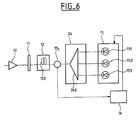
- Figure 6 is a diagram of a second embodiment of an optical device 200 of the invention for demultiplexing RZ pulses of distinct intensities.
- this device 200 has means 24 for extracting the signals as shifted by the shift means 12, with the means 24 advantageously comprising a WDM type demultiplexer 240.
- the path followed by the RZ pulses is similar to that described for the device 100.
- the intensity values of the RZ pulses at the inlet to the birefringent fiber and the birefringence values of the fiber are given purely by way of example.
- the number of non-zero levels on a given transmission channel can equally well be greater than or equal totwo, and the ratios between the intensities of distinct levels can be different.
- any kind of filter can be used, and its filter frequency can equally well be equal to the upper or to the lower shifted carrier frequency.
Landscapes
- Physics & Mathematics (AREA)
- Electromagnetism (AREA)
- Engineering & Computer Science (AREA)
- Computer Networks & Wireless Communication (AREA)
- Signal Processing (AREA)
- Optical Communication System (AREA)
Abstract
The invention provides an optical device (100) for demultiplexing at least two RZ optical signals (i1, i2, i3), each having a distinct non-zero intensity, said signals belonging to a given transmission channel having a given carrier frequency, and the device comprising: . means (12) for shifting said signals spectrally as a function of their intensities, thereby giving rise to shifted signals, each presenting at least one distinct shifted carrier frequency; and . means (14) for extracting said shifted signals as a function of their shifted carrier frequencies. <IMAGE>
Description
The present invention relates to the field of
optical fiber transmission. More particularly, it
relates to return to zero (RZ) signal transmission
systems such as transmission systems using soliton pulses
of distinct intensities, for example.
As is known, attempts are being made to increase the
capacity of optical transmission systems. In present
wavelength division multiplex (WDM) type optical fiber
transmission systems, it is desired to increase spectrum
efficiency expressed in terms of bits per second per
hertz (bit/s/Hz), i.e. the ratio of the modulation rate
over the frequency spacing between adjacent channels,
while avoiding interchannel spectrum overlap.
One of the means that can be envisaged is to make
use of multilevel RZ coding. Under such circumstances,
the RZ signals are RZ pulses having distinct intensities.
By way of example, for a channel having a given carrier
frequency, RZ pulses at a repetition rate of 10 GHz are
coded in four levels of distinct intensities namely one
zero level and three non-zero levels. This produces a
train of pulses at 20 gigabits per second (Gbit/s)
occupying a spectrum bandwidth that is about half the
width corresponding to a conventional binary pulse train
of two levels at 20 Gbit/s.
However, although it is presently known how to
generate RZ pulses of distinct intensities, means for
recovering and in particular for demultiplexing such
pulses of different levels are limited and provide poor
performance.
The only known solution consists in using electronic
means which are incapable of operating at very high rates
in order to avoid distorting the pulses because of nonlinearities.
An object of the invention is to provide an optical
device for demultiplexing RZ optical signals of distinct
intensities, in particular for high data rate optical
fiber transmission systems that are simple to manufacture
and operate.
More precisely, the invention provides an optical
device for demultiplexing at least two RZ optical
signals, each having a distinct non-zero intensity, said
signals belonging to a given transmission channel having
a given carrier frequency, and the device comprising:
Thus, the device of the invention makes it possible
to process the signals separately as a function of their
intensities. By way of example, for the 20 Gbit/s train
of four RZ signals of distinct level intensities
previously described, the device of the invention enables
three frequency-shifted signal trains to be extracted
together, each train being at the repetition rate of
10 GHz, i.e. at a rate compatible with conventional
detection systems. Thus, by incorporating the device of
the invention in a high data transmission system, it is
possible for the system to make use of high performance
multilevel coding.
Advantageously, the RZ signals of the invention can
be soliton pulses.
Known RZ signals include solitons which are
generally transmitted in the portion of an optical fiber
that presents abnormal dispersion. Solitons are pulses
having a sech2 hyperbolic secant waveform. With pulses of
this waveform, the non-linearity in the corresponding
portion of the fiber compensates for dispersion of the
optical signal. Soliton transmission is modelled in
conventional manner by the non-linear Schrödinger
equation.
It is not necessary to provide a soliton source in
order to transmit solitons since an optical fiber of
sufficient length can itself be very efficient at
delivering pulses that are solitons, even when starting
from pulses of Gaussian or square waveform.
Furthermore, C.R. Menyuk in "Stability of solitons
in birefringent optical fibers I: Equal propagation
amplitudes", published in Optics Letters, Vol. 12, No. 8,
August 1987, proposes a model of the effects of
birefringence on the propagation of RZ signals such as
solitons in monomode fibers. Birefringence, i.e. the
difference in refractive index between the two
polarization directions of an optical fiber, leads to a
soliton pulse being split into two components which
propagate at different speeds for each of the two
polarization directions. The article by C.R. Menyuk
shows that above a certain power level, the Kerr effect
leads to soliton pulses becoming stable in time by cross-phase
modulation between the soliton components
propagating with each of the two polarization directions.
Mutual time trapping then takes place between the
components with the two polarization directions; thus,
above a certain intensity level, the components in both
of the polarization directions travel together. The
threshold intensity depends on the birefringence of the
fiber.
M.N. Islam et al., in "Soliton trapping in
birefringent optical fibers" published in Optics Letters,
Vol. 14, No. 18, September 1989, describe an experimental
demonstration of orthogonally polarized solitons being
trapped in birefringent optical fibers; that experiment
confirmed the results put forward in the above-cited
article by C.R. Menyuk.
Those articles by C.R. Menyuk and M.N. Islam et al.
mention the case of soliton pulses. More generally,
other types of RZ signal can exist in which the
components on the two polarization directions of a
birefringent fiber become trapped by cross-phase
modulation, in the same manner as for solitons.
In a preferred embodiment, the means of the
invention for spectrally shifting the signals can thus
comprise a birefringent fiber. The birefringence of the
fiber can be greater than or equal to 1×10⁻⁵.
In this embodiment, each signal of intensity greater
than the threshold intensity is duplicated and thus
presents two shifted carrier frequencies disposed
symmetrically about the initial carrier frequency of the
transmission channel. The spacing between the shifted
carrier frequencies and the initial carrier frequency
increases with increasing intensity of the signal.
Furthermore, the two components of the shifted signal of
the invention coincide in time at the outlet from the
birefringent fiber.
To optimize spectral shifting, it is desirable for
the signals that are injected into the birefringent fiber
to be polarized in a direction that substantially bisects
the two polarization directions of the fiber.
Thus, in this embodiment, the optical device of the
invention preferably comprises means for polarizing the
signals, which means are disposed at the inlet to the
birefringent fiber.
Furthermore, in an embodiment of the invention, the
means of the invention for extracting the shifted signals
comprise a wavelength demultiplexer.
In another embodiment of the invention, the means
for the invention for extracting the shifted signals
comprise one discrete bandpass type filter per shifted
signal, each filter being centered on a distinct "filter"
frequency that is substantially equal to one or other of
the two shifted carrier frequencies of the associated
shifted signal.
In this embodiment, one-half of the half-height
bandwidth of each filter can be less than the frequency
spacing(s) between the filter frequency and the adjacent
filter frequency(ies).
This makes it possible to limit mixing between a
portion of the adjacent shifted signals with the
associated signal, thus enabling better data recovery.
Furthermore, the optical device of the invention can
include means for amplifying the signals, which means can
be located upstream from the shifting means.
When the spectrum shifting means comprise a
birefringent fiber, such an amplifier can serve to adjust
the intensity of the signals to beyond the given
threshold intensity.
Other characteristics and advantages of the
invention will appear on reading the following
description of embodiments of the invention, given by way
of example and with reference to the accompanying
drawings, in which:
In all of these figures, elements which are common,
i.e. which perform the same functions, are given the same
reference numerals.
In order to demultiplex RZ optical signals, the
invention proposes imparting differing spectrum shifts to
the RZ signals as a function of their respective
intensities, prior to extracting them individually.
To apply spectrum shifts to such signals as a
function of their intensities, the invention proposes
trapping signals propagating on the two polarization
directions in a birefringent optical fiber. As mentioned
above, such trapping occurs only above a certain
intensity threshold.
The invention applies in particular to soliton or to
other RZ signals whose components on the polarization
directions of a birefringent fiber can become trapped by
cross-phase modulation, as is the case for solitons.
Figure 1 is a diagram of a train S of four RZ
signals in the form of pulses i0, i1, i2, i3 transmitted in
succession from left to right in the figure. Time is
plotted along the abscissa, which is equivalent to length
along a transmission system; and intensity is plotted up
the ordinate. The first pulse i0 referred to the zero
level has zero intensity I0 implemented by practically
cutting off the signal source. The other three pulses i1,
i2, i3 referred to non-zero levels are of increasing non-zero
intensities respectively equal to I1, I2, and I3.
Such train S is also called multilevel signal. All of the
pulses belong to a given transmission channel having a
given carrier frequency. By way of example, the
transmission channel can form part of the C transmission
band (1530 nanometers (nm) to 1560 nm) or the L band
(1565 nm to 1610 nm). The repetition frequency of pulses
is for example 10 GHz leading to a rate of 20 Gbit/s.
Obviously, a higher rate is obtained by having a train
pulse at higher repetition frequency and/or coding with
more levels.
Figure 2 is a diagram of a first embodiment of an
optical demultiplexer device 100 of the invention which
comprises in succession:
In the embodiment of Figure 1, there is also
provided, upstream from the means 14, a coupler 131 having
two outlet branches a1 and a2. One of the outlet branches
a1 in combination with clock recovery means 16 and the
other a2 leading to another coupler 132 having three
outlet branches b1, b2, and b3.
The dynamic behavior of the device 100 is described
below with reference to the paths of the pulses i0, i1,
i2, and i3.
The pulses i1, i2, and i3 are initially injected into
the inlet of the device 100 via the amplifier 10 so that
the pulses i1, i2, and i3 present intensities that are
higher than the threshold intensity of the birefringent
fiber 120.
Thereafter, the pulses i1, i2, and i3 are polarized
by the means 12 to occupy a direction that bisects or
substantially bisects the two polarization directions of
the fiber 120 so as to generate two components (not
shown) per pulse, each component propagating on a
distinct polarization direction.
As mentioned above, for an inlet pulse that is
beneath a certain intensity referred to as the threshold
intensity, the two components propagate at different
speeds, so at the outlet from the fiber 120 two
components are obtained one on each of the two
polarization directions, in which the components have
become shifted in time, and both of these components are
spectrally at the frequency of the inlet RZ pulse, i.e.
at the initial carrier frequency.
In contrast, above this threshold intensity, the
Kerr effect serves to trap the components on the two
polarization directions; the components at the outlet
from the fiber therefore coincide in time, but are
spectrally shifted.
The corresponding threshold intensity is mentioned
in the above-cited articles by C.R. Menyuk and
M.N. Islam. The intensity necessary for achieving mutual
trapping between the two components in a birefringent
fiber can easily be determined experimentally, by
analyzing the spectrum and time positions of pulses
injected into the birefringent fiber 120.
By way of example, the fiber 120 can present the
following characteristics:
By way of example, in such a fiber, an optimal
intensity for trapping the components of a pulse on both
polarization directions is 84 picojoules (pJ). The fiber
120 then makes it possible to shift the pulses by not
less than 1 terahertz (THz). These values are given for
pulses having a full width at half maximum (FWHM) of
about 300 femtoseconds (fs) at a carrier wavelength equal
to 1.686 µm.
At the output from the shift means 120, the shifted
pulses enter the coupler131. Then, a small part (not
shown) of each shifted pulse is driven via the branch a1
to the clock recovery means 16 which provide for example
a sinusoidal electric clock signal CK sent to detection
means 15 for piloting signals. From the other branch a2
the shifted pulses enter the coupler 132 which produces
three pulses i'1, i'2, and i'3 of respective intensities
I1/3, I2/3, and I3/3 on each of the outlet branches b1, b2,
and b3. The branches b1, b2, and b3 lead to three
respective bandpass filters 141, 142, and 143. Each
filter 141, 142, and 143 serves to extract a single pulse
i'1, i'2, or i'3.
Each pulse i'1, i'2, or i'3 is injected to detection
means 15 and is converted into electric pulses (not
shown) by a photodiode 151, 152, 153. Detection means 15
include a chip (not shown) forming a pulse train starting
from all the electric pulses generated at the same
repetition frequency than the initial optic pulse train
S.
In addition, the shifting means 12 and extractor
means 14 are obviously transparent to a zero level pulse
(not shown) which passes through them.
Figure 3 shows curves 101, 102, and 103 representing
the respective spectra of the pulses i1, i2, and i3 at the
inlet to the device 100. Frequency is plotted along the
abscissa and power spectrum density is plotted up the
ordinate. In conventional manner, the RZ pulses are
represented by respective peaks centered on the given
carrier frequency fp.
Figure 4 is a diagram showing the spectra 111, 112,
and 113 of the pulses i1, i2, and i3 at the outlet from
the birefringent fiber 120. For each shifted pulse i1,
i2, and i3 this diagram shows the two spectra 111a & 111b,
112a & 112b, 113a & 113b of the two simultaneous
components that are frequency shifted symmetrically about
the carrier frequency fp. Thus each shifted pulse i1, i2,
and i3 presents two shifted carrier frequencies f1 & f11,
f2 & f22, and f3 & f33 respectively above and below the
carrier frequency fp. The representation of each spectrum
is schematic as each two shifted carrier frequencies per
pulse may be nearer from each other.
Figure 4 also shows a curve C specifying the filter
characteristic for a bandpass filter 142 suitable for use
in the invention. This rectangular filter characteristic
is centered on a "filter" frequency that is substantially
equal to the shifted carrier frequency f1 of the
associated shifted pulse i'1. The half-height bandwidth B
of the filter 142 is less than either of the frequency
spacings f3-f2 and f2-f1. The other filters 141 and 143
present characteristics that are similar (not shown).
Figure 5 is a diagram showing the spectra 121, 122,
and 123 of the pulses i'1, i'2, and i'3 at the outlet from
the device of the invention 100.
Pulses of distinct intensities have thus been
demultiplexed.
Figure 6 is a diagram of a second embodiment of an
optical device 200 of the invention for demultiplexing RZ
pulses of distinct intensities.
In addition to the elements 10, 11, 12 & 120, 131, 15
& 151 & 152 & 153, and 16 that are the same as in the
device 100, this device 200 has means 24 for extracting
the signals as shifted by the shift means 12, with the
means 24 advantageously comprising a WDM type
demultiplexer 240.
The path followed by the RZ pulses is similar to
that described for the device 100.
Naturally, the present invention is not limited to
the examples and embodiments described and shown, and the
invention can be the subject of numerous variants that
are available to the person skilled in the art.
The intensity values of the RZ pulses at the inlet
to the birefringent fiber and the birefringence values of
the fiber are given purely by way of example.
Similarly, the number of non-zero levels on a given
transmission channel can equally well be greater than or
equal totwo, and the ratios between the intensities of
distinct levels can be different.
It is also possible to provide as many devices of
the invention as there are data transmission channels so
as to cover an entire transmission window.
Furthermore, any kind of filter can be used, and its
filter frequency can equally well be equal to the upper
or to the lower shifted carrier frequency.
Claims (9)
- An optical device (100, 200) for demultiplexing at least two RZ optical signals (i1, i2, i3), each having a distinct non-zero intensity, said signals belonging to a given transmission channel having a given carrier frequency (fp), and the device comprising:· means (12) for shifting said signals spectrally as a function of their intensities, thereby giving rise to shifted signals each presenting at least one distinct shifted carrier frequency (f1 & f11, f2 & f22, and f3 & f33); and· means (14, 24) for extracting said shifted signals as a function of their shifted carrier frequencies.
- An optical device (100, 200) according to claim 1, characterized in that said RZ signals (i1, i2, i3) are soliton pulses.
- An optical device (100, 200) according to claim 1 or claim 2, characterized in that said means (12) for spectrally shifting said signals (i1, i2, i3) comprise a birefringent fiber (120).
- An optical device (100, 200) according to claim 3, characterized in that said fiber (120) presents birefringence greater than or equal to 1×10⁻⁵.
- An optical device (100, 200) according to claim 3 or claim 4, characterized in that it includes means (11) for polarizing said signals (i1, i2, i3) , said means being located at the inlet to said fiber (120).
- An optical device (200) according to any one of claims 1 to 5, characterized in that said means (24) for extracting said shifted signals comprise a wavelength demultiplexer (240).
- An optical device (100) according to any one of claims 1 to 5, characterized in that said means (14) for extracting said shifted signals comprise one discrete bandpass type filter (141, 142, 143) per shifted signal, each filter being centered on a distinct "filter" frequency substantially equal to one of said shifted carrier frequencies (f1, f2, f3) of the associated shifted signal.
- An optical device (100) according to claim 7, characterized in that one-half of the half-height bandwidth of each filter (141, 142, 143) is less than the spacing(s) between the filter frequency (f1, f2, f3) and the adjacent filter frequency(ies).
- An optical device (100, 200) according to any one of claims 1 to 8, characterized in that it comprises means (10) for amplifying said signals (i1, i2, i3), which means are located upstream from said shifting means (12).
Priority Applications (3)
| Application Number | Priority Date | Filing Date | Title |
|---|---|---|---|
| EP01440330A EP1300968A1 (en) | 2001-10-03 | 2001-10-03 | A device for demultiplexing optical RZ signals |
| US10/245,300 US20030063344A1 (en) | 2001-10-03 | 2002-09-18 | Device for demultiplexing optical RZ signals |
| CN02144223.1A CN1409143A (en) | 2001-10-03 | 2002-09-29 | Device for multipath resolving optical R2 signal |
Applications Claiming Priority (1)
| Application Number | Priority Date | Filing Date | Title |
|---|---|---|---|
| EP01440330A EP1300968A1 (en) | 2001-10-03 | 2001-10-03 | A device for demultiplexing optical RZ signals |
Publications (1)
| Publication Number | Publication Date |
|---|---|
| EP1300968A1 true EP1300968A1 (en) | 2003-04-09 |
Family
ID=8183312
Family Applications (1)
| Application Number | Title | Priority Date | Filing Date |
|---|---|---|---|
| EP01440330A Withdrawn EP1300968A1 (en) | 2001-10-03 | 2001-10-03 | A device for demultiplexing optical RZ signals |
Country Status (3)
| Country | Link |
|---|---|
| US (1) | US20030063344A1 (en) |
| EP (1) | EP1300968A1 (en) |
| CN (1) | CN1409143A (en) |
Family Cites Families (1)
| Publication number | Priority date | Publication date | Assignee | Title |
|---|---|---|---|---|
| CA1330242C (en) * | 1987-11-30 | 1994-06-14 | Gte Laboratories Incorporated | Subcarrier-multiplexed optical transmission systems using optical channel selection |
-
2001
- 2001-10-03 EP EP01440330A patent/EP1300968A1/en not_active Withdrawn
-
2002
- 2002-09-18 US US10/245,300 patent/US20030063344A1/en not_active Abandoned
- 2002-09-29 CN CN02144223.1A patent/CN1409143A/en active Pending
Non-Patent Citations (4)
| Title |
|---|
| HATAMI-HANZA H ET AL: "A MULTILEVEL SOLITON COMMUNICATION SYSTEM", JOURNAL OF LIGHTWAVE TECHNOLOGY, IEEE. NEW YORK, US, vol. 15, no. 1, 1997, pages 6 - 18, XP000642273, ISSN: 0733-8724 * |
| HATAMI-HANZA H ET AL: "Demonstration of all-optical demultiplexing of a multilevel soliton signal employing soliton decomposition and self-frequency shift", IEEE PHOTONICS TECHNOLOGY LETTERS, JUNE 1997, IEEE, USA, vol. 9, no. 6, pages 833 - 835, XP002193036, ISSN: 1041-1135 * |
| MENYUK C R ET AL: "Raman effect in birefringent optical fibers", OPTICS LETTERS, 15 APRIL 1991, USA, vol. 16, no. 8, pages 566 - 568, XP002193037, ISSN: 0146-9592 * |
| MORIOKA T ET AL: "ULTRAFAST POLARISATION-INDEPENDENT OPTICAL DEMULTIPLEXER USING OPTICAL CARRIER FREQUENCY SHIFT THROUGH CROSSPHASE MODULATION", ELECTRONICS LETTERS, IEE STEVENAGE, GB, vol. 28, no. 11, 21 May 1992 (1992-05-21), pages 1070 - 1072, XP000305903, ISSN: 0013-5194 * |
Also Published As
| Publication number | Publication date |
|---|---|
| CN1409143A (en) | 2003-04-09 |
| US20030063344A1 (en) | 2003-04-03 |
Similar Documents
| Publication | Publication Date | Title |
|---|---|---|
| DE69535619T2 (en) | Optical transmission system, optical multiplexing transmission system and associated methods | |
| US5953138A (en) | All-optical processing in communications systems | |
| US20030189745A1 (en) | Optical single sideband transmitter | |
| EP0892516B1 (en) | All-optical time-division demultiplexing circuit and all-optical TDM-WDM conversion circuit | |
| EP1531355A1 (en) | Wavelength divition multiplex optical regeneration system and wavelength division multiplex optical regeneration method | |
| WO1996013104A9 (en) | All-optical processing in communications systems | |
| Hansen Mulvad et al. | Ultra-high-speed optical serial-to-parallel data conversion by time-domain optical Fourier transformation in a silicon nanowire | |
| Cvecek et al. | Phase-preserving amplitude regeneration for a WDM RZ-DPSK signal using a nonlinear amplifying loop mirror | |
| EP0555063B1 (en) | Optical waveform shaping device | |
| US6814376B2 (en) | Method and system for generating short pulse signals | |
| US7587140B2 (en) | Optical time-division demultiplexing apparatus | |
| CN100353254C (en) | Optical switch and optical waveform monitoring device utilizing optical switch | |
| EP1300968A1 (en) | A device for demultiplexing optical RZ signals | |
| US8369711B2 (en) | Ethernet transmitter apparatus | |
| Suzuki et al. | Recent progress in optical soliton communication | |
| Yu et al. | 3R regeneration of a 40-Gbit/s optical signal by optical parametric amplification in a highly-nonlinear fiber | |
| Leclerc et al. | 40 Gbit/s polarization-independent, push-pull InP Mach-Zehnder modulator for all-optical regeneration | |
| Miyazaki et al. | All optical reshaping in 160 Gbit/s OTDM receiver using an XAM gate followed by an SPM discriminator | |
| US20020168138A1 (en) | Optical module for a parallel dispersion management | |
| Lu et al. | Wideband All-Optical Phase Interleaving Technology Enabling Phase-Multiplexing of 3x10-Gb/s DPSK-WDM into 30-Gb/s DPSK using FWM in HNLF | |
| Kaur et al. | Nonlinear effects and its impact on multichannel systems | |
| Spälter et al. | Single-channel data rates beyond 40Gbit/s | |
| Hecht | Slow Light and Fast Data Links: Report from OFC 2006 | |
| Yang et al. | Demonstration of a 16* 10-Gb/s OTDM system | |
| 孔德明 et al. | 80-GB all-optical serial-to-parallel convertor for QPSK signal based on cascaded phase modulators and optical filters |
Legal Events
| Date | Code | Title | Description |
|---|---|---|---|
| PUAI | Public reference made under article 153(3) epc to a published international application that has entered the european phase |
Free format text: ORIGINAL CODE: 0009012 |
|
| AK | Designated contracting states |
Kind code of ref document: A1 Designated state(s): AT BE CH CY DE DK ES FI FR GB GR IE IT LI LU MC NL PT SE TR Designated state(s): AT BE CH CY DE DK ES FI FR GB GR IE IT LI LU MC NL PT SE TR |
|
| AX | Request for extension of the european patent |
Extension state: AL LT LV MK RO SI |
|
| AKX | Designation fees paid |
Designated state(s): DE ES FR GB IT |
|
| STAA | Information on the status of an ep patent application or granted ep patent |
Free format text: STATUS: THE APPLICATION IS DEEMED TO BE WITHDRAWN |
|
| 18D | Application deemed to be withdrawn |
Effective date: 20031010 |