EP1300706A1 - Optical deinterleaver - Google Patents
Optical deinterleaver Download PDFInfo
- Publication number
- EP1300706A1 EP1300706A1 EP02013511A EP02013511A EP1300706A1 EP 1300706 A1 EP1300706 A1 EP 1300706A1 EP 02013511 A EP02013511 A EP 02013511A EP 02013511 A EP02013511 A EP 02013511A EP 1300706 A1 EP1300706 A1 EP 1300706A1
- Authority
- EP
- European Patent Office
- Prior art keywords
- signal
- channels
- wdm
- medium
- directing
- Prior art date
- Legal status (The legal status is an assumption and is not a legal conclusion. Google has not performed a legal analysis and makes no representation as to the accuracy of the status listed.)
- Withdrawn
Links
- 230000003287 optical effect Effects 0.000 title claims description 22
- 238000000034 method Methods 0.000 claims description 8
- 239000000835 fiber Substances 0.000 description 12
- 239000013307 optical fiber Substances 0.000 description 8
- 230000005540 biological transmission Effects 0.000 description 4
- 239000006185 dispersion Substances 0.000 description 4
- 238000001228 spectrum Methods 0.000 description 4
- 238000004891 communication Methods 0.000 description 3
- 238000003780 insertion Methods 0.000 description 2
- 230000037431 insertion Effects 0.000 description 2
- 238000004519 manufacturing process Methods 0.000 description 2
- 238000004806 packaging method and process Methods 0.000 description 2
- 230000003595 spectral effect Effects 0.000 description 2
- 230000008878 coupling Effects 0.000 description 1
- 238000010168 coupling process Methods 0.000 description 1
- 238000005859 coupling reaction Methods 0.000 description 1
- 239000013078 crystal Substances 0.000 description 1
- 239000000463 material Substances 0.000 description 1
- 238000000926 separation method Methods 0.000 description 1
Images


Classifications
-
- G—PHYSICS
- G02—OPTICS
- G02B—OPTICAL ELEMENTS, SYSTEMS OR APPARATUS
- G02B6/00—Light guides; Structural details of arrangements comprising light guides and other optical elements, e.g. couplings
- G02B6/24—Coupling light guides
- G02B6/26—Optical coupling means
- G02B6/28—Optical coupling means having data bus means, i.e. plural waveguides interconnected and providing an inherently bidirectional system by mixing and splitting signals
- G02B6/293—Optical coupling means having data bus means, i.e. plural waveguides interconnected and providing an inherently bidirectional system by mixing and splitting signals with wavelength selective means
- G02B6/29304—Optical coupling means having data bus means, i.e. plural waveguides interconnected and providing an inherently bidirectional system by mixing and splitting signals with wavelength selective means operating by diffraction, e.g. grating
- G02B6/29316—Light guides comprising a diffractive element, e.g. grating in or on the light guide such that diffracted light is confined in the light guide
- G02B6/29317—Light guides of the optical fibre type
-
- G—PHYSICS
- G02—OPTICS
- G02B—OPTICAL ELEMENTS, SYSTEMS OR APPARATUS
- G02B6/00—Light guides; Structural details of arrangements comprising light guides and other optical elements, e.g. couplings
- G02B6/24—Coupling light guides
- G02B6/26—Optical coupling means
- G02B6/28—Optical coupling means having data bus means, i.e. plural waveguides interconnected and providing an inherently bidirectional system by mixing and splitting signals
- G02B6/293—Optical coupling means having data bus means, i.e. plural waveguides interconnected and providing an inherently bidirectional system by mixing and splitting signals with wavelength selective means
- G02B6/29379—Optical coupling means having data bus means, i.e. plural waveguides interconnected and providing an inherently bidirectional system by mixing and splitting signals with wavelength selective means characterised by the function or use of the complete device
- G02B6/2938—Optical coupling means having data bus means, i.e. plural waveguides interconnected and providing an inherently bidirectional system by mixing and splitting signals with wavelength selective means characterised by the function or use of the complete device for multiplexing or demultiplexing, i.e. combining or separating wavelengths, e.g. 1xN, NxM
- G02B6/29386—Interleaving or deinterleaving, i.e. separating or mixing subsets of optical signals, e.g. combining even and odd channels into a single optical signal
Definitions
- the present invention relates to optical communication devices. More specifically, the present invention relates to an optical interleaver for multiplexing optical signals.
- FIG. 1A illustrates a plurality of optical channels, or signals, L 1 , L 2 , ..., L N multiplexed (by a multiplexer 10) as a single WDM signal carried by a first optical medium, for example optical fiber 11.
- the wavelength of the optical carrier of signal L2 is longer than the wavelength of the optical carrier of signal L1, and so on.
- a demultiplexer 12 is used to separate the individual channels of the WDM signal.
- the channels of the WDM signal are closely packed in the frequency spectrum.
- frequency spacing between the channels L 1 , L 2 ... L N may be 100 GHz, 50 GHz, or even less.
- Such a tightly packed WDM signal requires a complex and difficult-to-build demultiplexer 12. It is especially difficult to build demultiplexing devices with high resolution and high spectral efficiency to separate broad, closely spaced channels.
- An interleaver is a three-port wavelength-separation device that splits a WDM signal into even and odd channels.
- Figure 1B illustrates the use of an interleaver 14 to split the WDM signal into an odd-channel WDM signal (carried in a second medium 13 toward a first output port) including the odd channels L 1 , L 3 , ..., L N-1 of the WDM signal and an even-channel WDM signal (carried in a third medium 15 toward a second output port) including the even channels L 2 , L 4 , ..., L N of the WDM signal. Consequently, the frequency spacing between the channels of each of the split WDM signals (of fibers 13 and 15) is twice as wide as the frequency spacing of the input WDM signal. Therefore, the demultiplexers 16 and 18 are comparatively easier to build, thus less costly.
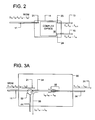
- the interleaver 14 of Figure 1B is illustrated in greater detail in Figure 2A.
- the incoming WDM signal 21 leaves the first fiber 14 and is separated to odd 23 and even 24 signal channels (collectively, "separated signals" 23 and 24) by intricate arrangements of various combinations of optical devices such as lenses, mirrors, crystals, rotators, wave guides, reflectors, polarizers, beam splitters, filters, and collimators (collectively illustrated as a box 16).
- optical devices such as lenses, mirrors, crystals, rotators, wave guides, reflectors, polarizers, beam splitters, filters, and collimators
- One shortcoming of the prior art interleavers is that there is a relatively high insertion loss when the separated signals 23 and 24 are directed into the output fibers 13 and 15, respectively.
- the optical arrangement 16 is a free-space or planar wave-guide device having coupling losses.
- the interleaver 14 is difficult and costly to manufacture because the free-space optical arrangement 16 and the output fibers 13 and 15 must be aligned such that each of the separated signals 23 and 24 is lined-up to enter core of the output fibers 13 and 15.
- the core of each of the output fibers 13 and 15 is typically no more than 10 microns in diameter. Due to the difficulty of the alignments, manufacturing and packaging of interleavers are very costly.
- an interleaver includes a circulator for directing an incoming wavelength division multiplexed (WDM) signal from a first signal medium to a second signal medium.
- the second signal medium has a grating section to reflect a portion of the WDM signal toward the circulator.
- the circulator directs the reflected signals to a third signal medium.
- an optical device includes an input means for receiving a wavelength division multiplexed (WDM) signal including at least four different wavelength optical channels referable as L1, L2, L3, and L4.
- the device also includes means for directing the WDM signal from the input means to a first output means.
- the first output means has grating to reflect even signal channels L2 and L4 back to the directing means.
- the directing means directs the reflected signals L2 and L4 to a second output means.
- a method of separating a wavelength division multiplexed (WDM) signal including a plurality of channels is described. First, the WDM signal is directed from a first medium to a second medium via a circulator. Then, alternating channels of the WDM signal are reflected back toward the circulator. Finally, reflected channels are directed to a third medium.
- WDM wavelength division multiplexed
- an apparatus includes a first signal medium for receiving a wavelength division multiplexed (WDM) signal and means for separating the WDM signal into even channels and odd channels, the means comprising at least one Bragg grating.
- WDM wavelength division multiplexed
- a method of separating a wavelength division multiplexed (WDM) signal including a plurality of channels is disclosed. First, odd and even channels are separated using one or more Bragg gratings. The odd channels are directed toward a first output and the even channels are directed toward a second output.
- WDM wavelength division multiplexed
- an apparatus includes a first coupler for receiving a wavelength division multiplexed (WDM) signal including a plurality of channels.
- the first coupler directs a first portion of the WDM signal into a first path and a second portion of the WDM signal into a second path.
- the first path includes a first grating section reflecting odd channels of the first portion of the WDM signal.
- the second path includes a second grating section reflecting odd channels of the second portion of the WDM signal.
- the first coupler combines the reflected odd channels from the first path and the reflected odd channels from the second path.
- the combined odd channels are directed toward an output of the first coupler.
- a second coupler combines even channels of the first portion of the WDM signal received from the first path and even channels of the second portion of the WDM signal received from the second path. The combined even channels are directed toward an output of the second coupler.
- Figure 1A illustrates transmission of multiple optical channels using multiplexing and demultiplexing techniques
- Figure 1B illustrates transmission of multiple optical channels using multiplexing, interleaving, and demultiplexing techniques
- Figure 2 illustrates the interleaver of Figure 1B
- Figure 3A illustrates an apparatus according to a first embodiment of the present invention
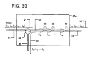
- Figure 3B illustrates an apparatus according to a second embodiment of the present invention
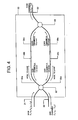
- Figure 4 illustrates an apparatus according to a third embodiment of the present invention.
- Figure 5 illustrates an interleaver according to a fourth embodiment of the present invention.
- the present invention is embodied in an optical apparatus including a directional separator for directing an incoming wavelength division multiplexed (WDM) signal from a first signal medium to a second signal medium.
- the second signal medium has multiple grating sections to reflect a portion of the WDM signal toward the circulator.
- the directional separator directs the reflected signals to a third signal medium. Because the incoming WDM signal does not leave various media, the signal need not be re-inserted into the output fibers (the second and the third signal medium). Consequently, the insertion loss is minimized and alignment and packaging problems are eliminated.
- the apparatus 30 is an interleaver 30.
- the WDM signal 21 enters the interleaver 30 via a first signal medium 11 such as an optical fiber or a wave-guide.
- the phrase "signal medium” includes, without limitation, optical fiber (or "fiber") and wave-guide.
- the WDM signal 21 includes N channels, or signals, referable to as L 1 , L 2 , L 3 , L 4 , ..., L N , with each channel at a unique optical frequency relative to the other channels of the WDM signal 21. Typically, but not necessarily, N is an even number.
- the medium 11 is connected to a directional separator 32 that directs the incoming WDM signal 21 to a second signal medium 34.
- the directional separator 32 can be a circulator 32. Circulators are known in the art.
- the second signal medium 34 includes a grating section 35 to reflect a portion of the WDM signal 21 back toward the circulator 32.
- the grating section includes a sampled Bragg grating such that all odd channels of the WDM signal 21 or all even channels of the WDM signal 21, but not both, are reflected back toward the directional separator 32.
- Sampled Bragg gratings are known in the art, and are described, for example, in Ibsen, M.; Eggleton, B.J.; Sceats, M.G.; Ouellette, F.: "Broadly tunable DBR fibre laser using sampled fibre Bragg gratings," Electronics Letters, Volume 31 Issue 1, 5 Jan. 1995 Page(s): 37-38.
- the reflected channels are directed to a third signal medium 44 as indicated by directional ray 39. In the illustrated example, all even channels are reflected by the grating section 35.
- the second signal medium 34 also serves as an a first output port, or means, 34 of the interleaver 30 for reflecting a portion (every other channels, for example even channels in the Figure) of the WDM signal 21 back toward the circulator 32 while allowing non-reflected portions (odd channels in the illustrated example) of the WDM signal 21 to pass through the interleaver 30 as a first output signal 31.
- the first output signal 31 includes signals L 1 , L 3 , ..., L N-1 .
- the grating section 35 of Figure 3A is implemented as a series of Bragg grating sections 36, 38, and 40.
- Figure 3B illustrates an alternative embodiment of the apparatus having certain alternate configuration. Portions of this embodiment is similar to those shown in Figure 3A.
- components in Figure 3B that are similar to components in Figure 3A are assigned the same reference numerals, analogous but changed components are assigned the same reference numerals accompanied by letter "a" and different components are assigned different reference numerals.
- the interleaver 30a has the series of Bragg grating sections 36, 38, and 40.
- the Bragg grating sections 36, 38, and 40 are designed, for instance using apodization, to produce a flat, sharp-edged (ideally "top-hat") passband of spectral width.
- the Bragg grating sections 36, 38, and 40 can be designed so that there is constant group delay across each passband spectrum.
- the Bragg grating sections 36, 38, and 40 can be designed so that there is a change in group delay across the passband spectrum (that is, chromatic dispersion) that undoes some or all of the chromatic dispersion of the preceding transmission fiber.
- the propagation speed of signals (or, inversely, their so-called group delay) through an optical fiber depends on their wavelength.
- a pulse that has dispersed as a result of traveling through optical fiber can be returned to its original undispersed shape by passing it through a device or material with equal and opposite dispersion, for example a specially-designed fiber Bragg grating.
- the first grating section 36 reflects the channel L 2
- the second grating section 38 reflects the channel L 4
- the final grating section 40 reflects channel L N
- the sections 36, 38, and 40 are designed to reflect alternating channels of the WDM signal 21.
- the reflected channels are directed to a third signal medium 44 as indicated by directional ray 39.
- the second signal medium 34 also serves as an a first output means 34 of the interleaver 30 for reflecting a portion of the WDM signal 21 back toward the circulator 32 while allowing non-reflected portions of the WDM signal 21 to pass through the interleaver 30 as a first output signal 31.
- the first output signal 31 includes signals L 1 , L 3 , ..., L N-1 .
- the circulator 32 in the present invention represents any device, apparatus, or means for separating and redirecting the reflected signals L 2 , L 4 , ..., L N from the incident input WDM signal 21.
- the third signal medium 44 also serves a second output port, or means, 44 of the interleaver 30 for carrying the alternating channels reflected by the sections 36, 38, and 40 of the second signal medium 34 and directed, by the circulator 32, to the third signal medium 44.
- the reflected channels directed to the third signal medium 44 are a second output signal 39 of the interleaver 30.
- the second output signal 39 includes channels L 2 , L 4 , ..., L N . If the channels of the WDM signal 21 were spaced at 50 GHz, then the spacing of the channels of the first output signal 31 is at 100 GHz, and the spacing of the channels of the second output signal 39 is at 100 GHz.
- An apparatus 50 includes a first coupler 52 for receiving a WDM signal 21 including a plurality of channels referable as channels L 1 , L 2 , L 3 , L 4 , ..., L N .
- the first coupler 52 directs the WDM signal 21 to a first path and a second path.
- Such couplers are known in the art: see for example www.adc.com.
- the first path includes signal medium 54a, a first grating section 54b, and signal medium 54c, all serially connected, the first path collectively referred to using reference number 54.
- the second path includes signal medium 56a, a second grating section 56b, and signal medium 56c, all serially connected, the second path collectively referred to using reference number 54.
- the channels of the WDM signal 21 are not separated, but all the channels of the WDM signal 21 are directed toward both the signal media 54a and 56a.
- the power of the WDM signal 21 is divided equally between the media 54a and 56a where these media carry 1 ⁇ 2 of the power of the incoming WDM signal 21 toward their respective grating sections 54b and 56b with the medium 54a carrying a first portion of the WDM signal 21 and the medium 56a carrying a second portion of the WDM signal 21.
- Each of the grating sections 54b and 56b reflects odd channels of the half-powered WDM signal (or even channels depending upon implementation) and allows even channels (or odd channels) to be transmitted toward a second coupler 58.
- the reflected odd channels (and their powers) from the first grating section 54b and from the second grating section 56b are combined by the first coupler 52. Their relative phases are controlled (by controlling the lengths of the coupler arms) so that the combined odd channels are directed toward an output medium 60 of the first coupler 52.
- the transmitted even channels form the first path 54 and from the second path 56 are combined by the second coupler 58. Their relative phases are controlled (by controlling the lengths of the coupler arms) so that they are directed toward an output medium 62 of the second coupler 58.
- the interleavers 30 of Figure 3A or 50 of Figure 4 can be cascaded to further separate the channels of the WDM signal 21.
- Figure 5 illustrates one embodiment of the cascaded interleaver 70 including a cascaded configuration of interleavers 72a, 72b, and 72c implemented according to the present invention.
- the cascaded interleaver 70 includes multiple instances of the interleaver 72, each interleaver 72 implemented according to the present invention.
- a first instance interleaver 72a separates the incoming WDM signal 21 into a first output signal 71 (odd channels) and a second output signal 79 (even channels) as discussed in connection with Figures 3A and 4.
- N is an integer greater than equal to eight and is divisible by four. Theoretically, N can be any number greater than one. In practice, N is often 64 or larger.
- the first output signal 71 acts as input to a second instance interleaver 72b that separates the first output signal 71 into a third output signal 81 (odd channels of the first output signal 71) and a fourth output signal 89 (even channels of the first output signal 71).
- the second output signal 79 acts as input to a third instance interleaver 72c that separates the second output signal 79 into a fifth output signal 91 (odd channels of the second output signal 79) and a sixth output signal 99 (even channels of the second output signal 79).
- the channels of the WDM signal 21 having 50 GHz spacing can be separated into output signals 81, 89, 91, and 99, each output signal having channels with 200 GHz spacing.
Landscapes
- Physics & Mathematics (AREA)
- General Physics & Mathematics (AREA)
- Optics & Photonics (AREA)
- Optical Communication System (AREA)
Abstract
An interleaver (30, 50) implemented using a directional
separator (32, 52) and Bragg grating sections is disclosed.
Wavelength division multiplexed (WDM) signal (21) enters the
interleaver (30, 50) and is directed from the input medium
(11) to a first output medium (34). The first output medium
(34) includes Bragg grating segments designed to reflect
alternating channels of the WDM signal (21). The reflected
channels (39) are directed to a second output medium (44).
Description
The present invention relates to optical
communication devices. More specifically, the present
invention relates to an optical interleaver for
multiplexing optical signals.
Often, to increase bandwidth (amount of data that
can be passed along a communications channel in a given
period of time) of optical communication channels such
as optical fiber, many optical signals of varying
wavelengths are multiplexed for transmission using a
single optical fiber. This is commonly known as a
wavelength division multiplexed (WDM) signal. Figure
1A illustrates a plurality of optical channels, or
signals, L1, L2, ..., LN multiplexed (by a multiplexer 10)
as a single WDM signal carried by a first optical
medium, for example optical fiber 11. The wavelength
of the optical carrier of signal L2 is longer than the
wavelength of the optical carrier of signal L1, and so
on. Then, a demultiplexer 12 is used to separate the
individual channels of the WDM signal. Increasingly,
the channels of the WDM signal are closely packed in
the frequency spectrum. For example, frequency spacing
between the channels L1, L2... LN may be 100 GHz, 50 GHz,
or even less. Such a tightly packed WDM signal
requires a complex and difficult-to-build demultiplexer
12. It is especially difficult to build demultiplexing
devices with high resolution and high spectral
efficiency to separate broad, closely spaced channels.
To reduce the complexity, and eventually the cost,
of the demultiplexer 12, interleavers are used to
increase the space, in the frequency spectrum, between
the channels. An interleaver is a three-port
wavelength-separation device that splits a WDM signal
into even and odd channels. Figure 1B illustrates the
use of an interleaver 14 to split the WDM signal into
an odd-channel WDM signal (carried in a second medium
13 toward a first output port) including the odd
channels L1, L3, ..., LN-1 of the WDM signal and an even-channel
WDM signal (carried in a third medium 15 toward
a second output port) including the even channels L2,
L4, ..., LN of the WDM signal. Consequently, the
frequency spacing between the channels of each of the
split WDM signals (of fibers 13 and 15) is twice as
wide as the frequency spacing of the input WDM signal.
Therefore, the demultiplexers 16 and 18 are
comparatively easier to build, thus less costly.
However, the interleavers, as used in the current
state of the art, are difficult to build and have
various shortcomings. The interleaver 14 of Figure 1B
is illustrated in greater detail in Figure 2A. In this
example of a prior art interleaver 14, the incoming WDM
signal 21 leaves the first fiber 14 and is separated to
odd 23 and even 24 signal channels (collectively,
"separated signals" 23 and 24) by intricate
arrangements of various combinations of optical devices
such as lenses, mirrors, crystals, rotators, wave
guides, reflectors, polarizers, beam splitters,
filters, and collimators (collectively illustrated as a
box 16). For example, see U.S. Patent Nos. 6,130,971
(granted to Cao) and 6,212,313 (granted to Li) for
interleavers implemented using complex and intricate
configuration of optical devices. Finally, the
separated odd 23 and even 24 channels (each channel
being a light beam) are inserted into output optical
fibers 13 and 15 respectively. Here, the WDM signal
21, the odd channels of the WDM signal 23, and the-even
channels of the WDM signal 24 are illustrated using
directional arrows in Figure 2A. These arrows are used
to indicate the general direction of the signals and
not used to indicate ray traces of optics art.
One shortcoming of the prior art interleavers is
that there is a relatively high insertion loss when the
separated signals 23 and 24 are directed into the
output fibers 13 and 15, respectively. This is because
the optical arrangement 16 is a free-space or planar
wave-guide device having coupling losses. More
importantly, the interleaver 14 is difficult and costly
to manufacture because the free-space optical
arrangement 16 and the output fibers 13 and 15 must be
aligned such that each of the separated signals 23 and
24 is lined-up to enter core of the output fibers 13
and 15. The core of each of the output fibers 13 and
15 is typically no more than 10 microns in diameter.
Due to the difficulty of the alignments, manufacturing
and packaging of interleavers are very costly.
Accordingly, there remains a need for an
interleaver that eliminates or reduces the shortcomings
of the current-art interleavers as discussed above.
These needs are met by the present invention.
According to a first aspect of the present invention,
an interleaver includes a circulator for directing an
incoming wavelength division multiplexed (WDM) signal
from a first signal medium to a second signal medium.
The second signal medium has a grating section to
reflect a portion of the WDM signal toward the
circulator. The circulator directs the reflected
signals to a third signal medium.
According to a second aspect of the present
invention, an optical device includes an input means
for receiving a wavelength division multiplexed (WDM)
signal including at least four different wavelength
optical channels referable as L1, L2, L3, and L4. The
device also includes means for directing the WDM signal
from the input means to a first output means. The
first output means has grating to reflect even signal
channels L2 and L4 back to the directing means. The
directing means directs the reflected signals L2 and L4
to a second output means.
According to a third aspect of the present
invention, a method of separating a wavelength division
multiplexed (WDM) signal including a plurality of
channels is described. First, the WDM signal is
directed from a first medium to a second medium via a
circulator. Then, alternating channels of the WDM
signal are reflected back toward the circulator.
Finally, reflected channels are directed to a third
medium.
According to a fourth aspect of the present
invention, an apparatus includes a first signal medium
for receiving a wavelength division multiplexed (WDM)
signal and means for separating the WDM signal into
even channels and odd channels, the means comprising at
least one Bragg grating.
According to a fifth aspect of the present
invention, a method of separating a wavelength division
multiplexed (WDM) signal including a plurality of
channels is disclosed. First, odd and even channels
are separated using one or more Bragg gratings. The
odd channels are directed toward a first output and the
even channels are directed toward a second output.
According to a fifth aspect of the present
invention, an apparatus includes a first coupler for
receiving a wavelength division multiplexed (WDM)
signal including a plurality of channels. The first
coupler directs a first portion of the WDM signal into
a first path and a second portion of the WDM signal
into a second path. The first path includes a first
grating section reflecting odd channels of the first
portion of the WDM signal. The second path includes a
second grating section reflecting odd channels of the
second portion of the WDM signal. The first coupler
combines the reflected odd channels from the first path
and the reflected odd channels from the second path.
The combined odd channels are directed toward an output
of the first coupler. A second coupler combines even
channels of the first portion of the WDM signal
received from the first path and even channels of the
second portion of the WDM signal received from the
second path. The combined even channels are directed
toward an output of the second coupler.
Other aspects and advantages of the present
invention will become apparent from the following
detailed description, taken in combination with the
accompanying drawings, illustrating by way of example
the principles of the invention.
Figure 1A illustrates transmission of multiple
optical channels using multiplexing and demultiplexing
techniques;
Figure 1B illustrates transmission of multiple
optical channels using multiplexing, interleaving, and
demultiplexing techniques;
Figure 2 illustrates the interleaver of Figure 1B;
Figure 3A illustrates an apparatus according to a
first embodiment of the present invention;
Figure 3B illustrates an apparatus according to a
second embodiment of the present invention;
Figure 4 illustrates an apparatus according to a
third embodiment of the present invention; and
Figure 5 illustrates an interleaver according to a
fourth embodiment of the present invention.
As shown in the drawings for purposes of
illustration, the present invention is embodied in an
optical apparatus including a directional separator for
directing an incoming wavelength division multiplexed
(WDM) signal from a first signal medium to a second
signal medium. The second signal medium has multiple
grating sections to reflect a portion of the WDM signal
toward the circulator. The directional separator
directs the reflected signals to a third signal medium.
Because the incoming WDM signal does not leave various
media, the signal need not be re-inserted into the
output fibers (the second and the third signal medium).
Consequently, the insertion loss is minimized and
alignment and packaging problems are eliminated.
Referring to Figure 3A, an apparatus 30 according
to one embodiment of the present invention is
illustrated. In this embodiment, the apparatus 30 is
an interleaver 30. The WDM signal 21 enters the
interleaver 30 via a first signal medium 11 such as an
optical fiber or a wave-guide. Here, the phrase
"signal medium" includes, without limitation, optical
fiber (or "fiber") and wave-guide. The WDM signal 21
includes N channels, or signals, referable to as L1,
L2, L3, L4, ..., LN, with each channel at a unique optical
frequency relative to the other channels of the WDM
signal 21. Typically, but not necessarily, N is an
even number. The medium 11 is connected to a
directional separator 32 that directs the incoming WDM
signal 21 to a second signal medium 34. For example,
the directional separator 32 can be a circulator 32.
Circulators are known in the art.
The second signal medium 34 includes a grating
section 35 to reflect a portion of the WDM signal 21
back toward the circulator 32. In the present example,
the grating section includes a sampled Bragg grating
such that all odd channels of the WDM signal 21 or all
even channels of the WDM signal 21, but not both, are
reflected back toward the directional separator 32.
Sampled Bragg gratings are known in the art, and are
described, for example, in Ibsen, M.; Eggleton, B.J.;
Sceats, M.G.; Ouellette, F.: "Broadly tunable DBR fibre
laser using sampled fibre Bragg gratings,"
Electronics Letters, Volume 31 Issue 1, 5 Jan. 1995
Page(s): 37-38. The reflected channels are directed to
a third signal medium 44 as indicated by directional
ray 39. In the illustrated example, all even channels
are reflected by the grating section 35.
The result is that, the second signal medium 34
also serves as an a first output port, or means, 34 of
the interleaver 30 for reflecting a portion (every
other channels, for example even channels in the
Figure) of the WDM signal 21 back toward the circulator
32 while allowing non-reflected portions (odd channels
in the illustrated example) of the WDM signal 21 to
pass through the interleaver 30 as a first output
signal 31. In the example, the first output signal 31
includes signals L1, L3, ..., LN-1.
As illustrated in Figure 3B, in an alternative
embodiment, the grating section 35 of Figure 3A is
implemented as a series of Bragg grating sections 36,
38, and 40. Figure 3B illustrates an alternative
embodiment of the apparatus having certain alternate
configuration. Portions of this embodiment is similar
to those shown in Figure 3A. For convenience,
components in Figure 3B that are similar to components
in Figure 3A are assigned the same reference numerals,
analogous but changed components are assigned the same
reference numerals accompanied by letter "a" and
different components are assigned different reference
numerals. In Figure 3B, the interleaver 30a has the
series of Bragg grating sections 36, 38, and 40. The
Bragg grating sections 36, 38, and 40 are designed, for
instance using apodization, to produce a flat, sharp-edged
(ideally "top-hat") passband of spectral width.
The Bragg grating sections 36, 38, and 40 can be
designed so that there is constant group delay across
each passband spectrum. Alternatively, the Bragg
grating sections 36, 38, and 40 can be designed so that
there is a change in group delay across the passband
spectrum (that is, chromatic dispersion) that undoes
some or all of the chromatic dispersion of the
preceding transmission fiber. The propagation speed
of signals (or, inversely, their so-called group delay)
through an optical fiber depends on their wavelength.
This phenomenon is known as chromatic dispersion, and
it causes pulse broadening, and hence overlap between
adjacent pulses, which results in errors in
distinguishing transmitted digital ones from digital
zeroes. A pulse that has dispersed as a result of
traveling through optical fiber can be returned to its
original undispersed shape by passing it through a
device or material with equal and opposite dispersion,
for example a specially-designed fiber Bragg grating.
In the illustrated example, the first grating
section 36 reflects the channel L2, the second grating
section 38 reflects the channel L4, and so on until the
final grating section 40 reflects channel LN. Here,
the sections 36, 38, and 40 are designed to reflect
alternating channels of the WDM signal 21. The
reflected channels are directed to a third signal
medium 44 as indicated by directional ray 39. The
result is that, the second signal medium 34 also serves
as an a first output means 34 of the interleaver 30 for
reflecting a portion of the WDM signal 21 back toward
the circulator 32 while allowing non-reflected portions
of the WDM signal 21 to pass through the interleaver 30
as a first output signal 31. In the example, the first
output signal 31 includes signals L1, L3, ..., LN-1. The
circulator 32 in the present invention represents any
device, apparatus, or means for separating and
redirecting the reflected signals L2, L4, ..., LN from the
incident input WDM signal 21.
Likewise, the third signal medium 44 also serves a
second output port, or means, 44 of the interleaver 30
for carrying the alternating channels reflected by the
sections 36, 38, and 40 of the second signal medium 34
and directed, by the circulator 32, to the third signal
medium 44. The reflected channels directed to the
third signal medium 44 are a second output signal 39 of
the interleaver 30. In the example, the second output
signal 39 includes channels L2, L4, ..., LN. If the
channels of the WDM signal 21 were spaced at 50 GHz,
then the spacing of the channels of the first output
signal 31 is at 100 GHz, and the spacing of the
channels of the second output signal 39 is at 100 GHz.
Yet another embodiment of the present invention is
illustrated by Figure 4. An apparatus 50 includes a
first coupler 52 for receiving a WDM signal 21
including a plurality of channels referable as channels
L1, L2, L3, L4, ..., LN. The first coupler 52 directs the
WDM signal 21 to a first path and a second path. Such
couplers are known in the art: see for example
www.adc.com.
The first path includes signal medium 54a, a first
grating section 54b, and signal medium 54c, all
serially connected, the first path collectively
referred to using reference number 54. The second path
includes signal medium 56a, a second grating section
56b, and signal medium 56c, all serially connected, the
second path collectively referred to using reference
number 54. Here, the channels of the WDM signal 21 are
not separated, but all the channels of the WDM signal
21 are directed toward both the signal media 54a and
56a. However, the power of the WDM signal 21 is
divided equally between the media 54a and 56a where
these media carry ½ of the power of the incoming WDM
signal 21 toward their respective grating sections 54b
and 56b with the medium 54a carrying a first portion of
the WDM signal 21 and the medium 56a carrying a second
portion of the WDM signal 21. Each of the grating
sections 54b and 56b reflects odd channels of the half-powered
WDM signal (or even channels depending upon
implementation) and allows even channels (or odd
channels) to be transmitted toward a second coupler 58.
The reflected odd channels (and their powers) from
the first grating section 54b and from the second
grating section 56b are combined by the first coupler
52. Their relative phases are controlled (by
controlling the lengths of the coupler arms) so that
the combined odd channels are directed toward an output
medium 60 of the first coupler 52.
The transmitted even channels form the first path
54 and from the second path 56 are combined by the
second coupler 58. Their relative phases are
controlled (by controlling the lengths of the coupler
arms) so that they are directed toward an output medium
62 of the second coupler 58.
The interleavers 30 of Figure 3A or 50 of Figure 4
can be cascaded to further separate the channels of the
WDM signal 21. Figure 5 illustrates one embodiment of
the cascaded interleaver 70 including a cascaded
configuration of interleavers 72a, 72b, and 72c
implemented according to the present invention.
Referring to Figure 5, the cascaded interleaver 70
includes multiple instances of the interleaver 72, each
interleaver 72 implemented according to the present
invention.
A first instance interleaver 72a separates the
incoming WDM signal 21 into a first output signal 71
(odd channels) and a second output signal 79 (even
channels) as discussed in connection with Figures 3A
and 4. In this example, N is an integer greater than
equal to eight and is divisible by four.
Theoretically, N can be any number greater than one.
In practice, N is often 64 or larger.
The first output signal 71 acts as input to a
second instance interleaver 72b that separates the
first output signal 71 into a third output signal 81
(odd channels of the first output signal 71) and a
fourth output signal 89 (even channels of the first
output signal 71).
The second output signal 79 acts as input to a
third instance interleaver 72c that separates the
second output signal 79 into a fifth output signal 91
(odd channels of the second output signal 79) and a
sixth output signal 99 (even channels of the second
output signal 79).
Using the cascaded interleaver 70, the channels of
the WDM signal 21 having 50 GHz spacing can be
separated into output signals 81, 89, 91, and 99, each
output signal having channels with 200 GHz spacing.
From the foregoing, it will be appreciated that
the apparatus and the methods of the present invention
is novel and offers advantages over the current art.
Although specific embodiment of the invention are
described and illustrated above, the invention is not
to be limited to the specific forms or arrangements of
parts so described and illustrated. For example, in
the above sample embodiments of the present invention,
roles of the odd channels and the even channels can be
reversed and still be within the scope of the present
invention. The invention is limited only by the
claims.
Claims (10)
- An apparatus (30) comprising:a circulator (32) for directing an incoming wavelength division multiplexed (WDM) signal (21) from a first signal medium (11) to a second signal medium (34);the second signal medium (34) having a grating section (35) to reflect a portion (39) of the WDM signal (21) toward the circulator (32); andthe circulator (32) directing the reflected signals (39) to a third signal medium (44).
- The apparatus (30) recited in claim 1 wherein the second signal medium (34) reflects every other channel of the WDM signal (21).
- The apparatus (30) recited in claim 1 wherein the grating section (35) includes sampled Bragg grating.
- An optical device (30) comprising:input means (11) for receiving wavelength division multiplexed (WDM) signal (21) including at least four different wavelength optical channels referable as L1, L2, L3, and L4;means (32) for directing the WDM signal (21) from the input means (11) to a first output means (34);the first output means (34) having a grating (35) to reflect even signal channels L2 and L4 back to the directing means (32); andthe directing means (32) directing the reflected signals L2 and L4 to a second output means (44).
- A method of separating a wavelength division multiplexed (WDM) signal (21) including a plurality of channels, the method comprising:directing the WDM signal (21) from a first medium (21) to a second medium (44) via a circulator (32);reflecting alternating channels (39) of the WDM signal (21) back toward the circulator (32); anddirecting the reflected channels (39) to a third medium (44).
- The method recited in claim 5 wherein the alternating channels (39) reflect on Bragg grating sections of the second medium (34).
- An apparatus (50) comprising:a first signal medium for receiving a wavelength division multiplexed (WDM) signal (21); andmeans (54b, 56b) for separating the WDM signal into even channels and odd channels, the means (54b, 56b) comprising at least one Bragg grating.
- The apparatus (50) recited in claim 7 further comprising a directional separator (52) to direct the even channels to a first output port (60) and the odd channels to a second output port (52).
- The apparatus (50) recited in claim 8 wherein the directional separator (52) comprises a circulator.
- The apparatus (50) recited in claim 8 wherein the directional separator (52) comprises a coupler.
Applications Claiming Priority (2)
| Application Number | Priority Date | Filing Date | Title |
|---|---|---|---|
| US09/972,803 US20030068120A1 (en) | 2001-10-05 | 2001-10-05 | Optical interleaver |
| US972803 | 2001-10-05 |
Publications (1)
| Publication Number | Publication Date |
|---|---|
| EP1300706A1 true EP1300706A1 (en) | 2003-04-09 |
Family
ID=25520166
Family Applications (1)
| Application Number | Title | Priority Date | Filing Date |
|---|---|---|---|
| EP02013511A Withdrawn EP1300706A1 (en) | 2001-10-05 | 2002-06-17 | Optical deinterleaver |
Country Status (3)
| Country | Link |
|---|---|
| US (1) | US20030068120A1 (en) |
| EP (1) | EP1300706A1 (en) |
| JP (1) | JP2003177274A (en) |
Families Citing this family (4)
| Publication number | Priority date | Publication date | Assignee | Title |
|---|---|---|---|---|
| JP4740526B2 (en) * | 2003-08-29 | 2011-08-03 | 住友大阪セメント株式会社 | Wavelength selection method and apparatus |
| US7768708B1 (en) | 2006-02-03 | 2010-08-03 | Raytheon Company | Light source having spatially interleaved light beams |
| KR101345788B1 (en) | 2013-01-18 | 2014-01-16 | 한국광기술원 | High resolution optical coherence tomography using wavelength division multiplexing coupler(wdm) and wide band splitter |
| US12092863B2 (en) * | 2021-10-18 | 2024-09-17 | Cisco Technology, Inc. | Fabrication-tolerant on-chip multiplexers and demultiplexers |
Citations (4)
| Publication number | Priority date | Publication date | Assignee | Title |
|---|---|---|---|---|
| WO1999008143A1 (en) * | 1997-08-12 | 1999-02-18 | University Of Southampton | Optical wavelength division multiplexer |
| WO2001005082A1 (en) * | 1999-07-13 | 2001-01-18 | Jds Uniphase Corporation | Method and devices for multiplexing and de-multiplexing multiple wavelengths |
| US6317539B1 (en) * | 1999-09-17 | 2001-11-13 | Jds Uniphase Corporation | Interleaved sampled and chirped optical waveguide gratings for WDM channel operations and resulting devices |
| WO2002025328A2 (en) * | 2000-09-20 | 2002-03-28 | Phaethon Communications | Sampled bragg gratings for wdm applications |
-
2001
- 2001-10-05 US US09/972,803 patent/US20030068120A1/en not_active Abandoned
-
2002
- 2002-06-17 EP EP02013511A patent/EP1300706A1/en not_active Withdrawn
- 2002-10-04 JP JP2002292232A patent/JP2003177274A/en active Pending
Patent Citations (4)
| Publication number | Priority date | Publication date | Assignee | Title |
|---|---|---|---|---|
| WO1999008143A1 (en) * | 1997-08-12 | 1999-02-18 | University Of Southampton | Optical wavelength division multiplexer |
| WO2001005082A1 (en) * | 1999-07-13 | 2001-01-18 | Jds Uniphase Corporation | Method and devices for multiplexing and de-multiplexing multiple wavelengths |
| US6317539B1 (en) * | 1999-09-17 | 2001-11-13 | Jds Uniphase Corporation | Interleaved sampled and chirped optical waveguide gratings for WDM channel operations and resulting devices |
| WO2002025328A2 (en) * | 2000-09-20 | 2002-03-28 | Phaethon Communications | Sampled bragg gratings for wdm applications |
Non-Patent Citations (2)
| Title |
|---|
| HUEBNER J ET AL: "STRONG SAMPLED BRAGG GRATINGS FOR WDM APPLICATIONS", IEEE PHOTONICS TECHNOLOGY LETTERS, IEEE INC. NEW YORK, US, vol. 10, no. 4, 1 April 1998 (1998-04-01), pages 552 - 554, XP000754219, ISSN: 1041-1135 * |
| LOH W H ET AL: "NOVEL DESIGNS FOR SAMPLED GRATING-BASED MULTIPLEXERS-DEMULTIPLEXERS", OPTICS LETTERS, OPTICAL SOCIETY OF AMERICA, WASHINGTON, US, vol. 24, no. 21, 1 November 1999 (1999-11-01), pages 1457 - 1459, XP000893673, ISSN: 0146-9592 * |
Also Published As
| Publication number | Publication date |
|---|---|
| JP2003177274A (en) | 2003-06-27 |
| US20030068120A1 (en) | 2003-04-10 |
Similar Documents
| Publication | Publication Date | Title |
|---|---|---|
| US6339474B2 (en) | Interferometric optical device including an optical resonator | |
| US5982518A (en) | Optical add-drop multiplexers compatible with very dense WDM optical communication systems | |
| US5748349A (en) | Gratings-based optical add-drop multiplexers for WDM optical communication system | |
| EP0568236A2 (en) | Efficient reflective optical multiplexers and demultiplexers | |
| CA2245054C (en) | Multi-pass optical filter | |
| JPH07212304A (en) | Optical dispersion compensator | |
| JP3448182B2 (en) | All-optical fiber optical router | |
| CA2220319C (en) | Hybrid bi-directional wavelength division multiplexing device | |
| CA2241707C (en) | Optical drop circuit having group delay compensation | |
| US6381052B1 (en) | Multiplexors with a flat top spectral channel shape | |
| EP1192494A1 (en) | Method and apparatus for higher-order chromatic dispersion compensation | |
| US6678441B1 (en) | Multireflector fiber optic filter apparatus and method | |
| US20030068120A1 (en) | Optical interleaver | |
| KR101317965B1 (en) | Optical interleavers and de-interleavers | |
| CA2326973A1 (en) | Optical demultiplexing/multiplexing device | |
| WO1999008143A1 (en) | Optical wavelength division multiplexer | |
| US20010055442A1 (en) | Optical wavelength-division multiplexing and demultiplexing by using a common optical bandpass filter for adding, dropping, or excanging one or more channels | |
| US6546167B1 (en) | Tunable grating optical device | |
| US8005328B2 (en) | Optical add/drop module | |
| US20030091276A1 (en) | Grating-based MUX/DMUX with expanded waveguides | |
| CA2281044A1 (en) | Optical multiplexor/demultiplexor | |
| US20020131142A1 (en) | System and method for tailoring dispersion within an optical communication system | |
| CA2326990A1 (en) | Multiplexing/demultiplexing optical circuit | |
| JP2600507B2 (en) | Optical multiplexer / demultiplexer | |
| Suzuki et al. | 40-wavelength channelized tunable optical dispersion compensator with increased bandwidth consisting of arrayed waveguide gratings and liquid crystal on silicon |
Legal Events
| Date | Code | Title | Description |
|---|---|---|---|
| PUAI | Public reference made under article 153(3) epc to a published international application that has entered the european phase |
Free format text: ORIGINAL CODE: 0009012 |
|
| AK | Designated contracting states |
Kind code of ref document: A1 Designated state(s): AT BE CH CY DE DK ES FI FR GB GR IE IT LI LU MC NL PT SE TR Designated state(s): AT BE CH CY DE DK ES FI FR GB GR IE IT LI LU MC NL PT SE TR |
|
| AX | Request for extension of the european patent |
Extension state: AL LT LV MK RO SI |
|
| STAA | Information on the status of an ep patent application or granted ep patent |
Free format text: STATUS: THE APPLICATION HAS BEEN WITHDRAWN |
|
| 18W | Application withdrawn |
Effective date: 20030723 |