EP1300599A2 - Electronic apparatus - Google Patents
Electronic apparatus Download PDFInfo
- Publication number
- EP1300599A2 EP1300599A2 EP02256773A EP02256773A EP1300599A2 EP 1300599 A2 EP1300599 A2 EP 1300599A2 EP 02256773 A EP02256773 A EP 02256773A EP 02256773 A EP02256773 A EP 02256773A EP 1300599 A2 EP1300599 A2 EP 1300599A2
- Authority
- EP
- European Patent Office
- Prior art keywords
- frictional
- electronic apparatus
- frictional member
- sliding
- panel unit
- Prior art date
- Legal status (The legal status is an assumption and is not a legal conclusion. Google has not performed a legal analysis and makes no representation as to the accuracy of the status listed.)
- Withdrawn
Links
Images



Classifications
-
- G—PHYSICS
- G06—COMPUTING OR CALCULATING; COUNTING
- G06F—ELECTRIC DIGITAL DATA PROCESSING
- G06F1/00—Details not covered by groups G06F3/00 - G06F13/00 and G06F21/00
- G06F1/16—Constructional details or arrangements
- G06F1/1613—Constructional details or arrangements for portable computers
- G06F1/1633—Constructional details or arrangements of portable computers not specific to the type of enclosures covered by groups G06F1/1615 - G06F1/1626
- G06F1/1675—Miscellaneous details related to the relative movement between the different enclosures or enclosure parts
- G06F1/1679—Miscellaneous details related to the relative movement between the different enclosures or enclosure parts for locking or maintaining the movable parts of the enclosure in a fixed position, e.g. latching mechanism at the edge of the display in a laptop or for the screen protective cover of a PDA
-
- F—MECHANICAL ENGINEERING; LIGHTING; HEATING; WEAPONS; BLASTING
- F16—ENGINEERING ELEMENTS AND UNITS; GENERAL MEASURES FOR PRODUCING AND MAINTAINING EFFECTIVE FUNCTIONING OF MACHINES OR INSTALLATIONS; THERMAL INSULATION IN GENERAL
- F16C—SHAFTS; FLEXIBLE SHAFTS; ELEMENTS OR CRANKSHAFT MECHANISMS; ROTARY BODIES OTHER THAN GEARING ELEMENTS; BEARINGS
- F16C11/00—Pivots; Pivotal connections
- F16C11/04—Pivotal connections
- F16C11/10—Arrangements for locking
- F16C11/103—Arrangements for locking frictionally clamped
-
- F—MECHANICAL ENGINEERING; LIGHTING; HEATING; WEAPONS; BLASTING
- F16—ENGINEERING ELEMENTS AND UNITS; GENERAL MEASURES FOR PRODUCING AND MAINTAINING EFFECTIVE FUNCTIONING OF MACHINES OR INSTALLATIONS; THERMAL INSULATION IN GENERAL
- F16M—FRAMES, CASINGS OR BEDS OF ENGINES, MACHINES OR APPARATUS, NOT SPECIFIC TO ENGINES, MACHINES OR APPARATUS PROVIDED FOR ELSEWHERE; STANDS; SUPPORTS
- F16M11/00—Stands or trestles as supports for apparatus or articles placed thereon ; Stands for scientific apparatus such as gravitational force meters
- F16M11/02—Heads
- F16M11/04—Means for attachment of apparatus; Means allowing adjustment of the apparatus relatively to the stand
- F16M11/06—Means for attachment of apparatus; Means allowing adjustment of the apparatus relatively to the stand allowing pivoting
- F16M11/10—Means for attachment of apparatus; Means allowing adjustment of the apparatus relatively to the stand allowing pivoting around a horizontal axis
-
- G—PHYSICS
- G06—COMPUTING OR CALCULATING; COUNTING
- G06F—ELECTRIC DIGITAL DATA PROCESSING
- G06F1/00—Details not covered by groups G06F3/00 - G06F13/00 and G06F21/00
- G06F1/16—Constructional details or arrangements
- G06F1/1613—Constructional details or arrangements for portable computers
- G06F1/1615—Constructional details or arrangements for portable computers with several enclosures having relative motions, each enclosure supporting at least one I/O or computing function
- G06F1/1616—Constructional details or arrangements for portable computers with several enclosures having relative motions, each enclosure supporting at least one I/O or computing function with folding flat displays, e.g. laptop computers or notebooks having a clamshell configuration, with body parts pivoting to an open position around an axis parallel to the plane they define in closed position
-
- G—PHYSICS
- G06—COMPUTING OR CALCULATING; COUNTING
- G06F—ELECTRIC DIGITAL DATA PROCESSING
- G06F1/00—Details not covered by groups G06F3/00 - G06F13/00 and G06F21/00
- G06F1/16—Constructional details or arrangements
- G06F1/1613—Constructional details or arrangements for portable computers
- G06F1/1633—Constructional details or arrangements of portable computers not specific to the type of enclosures covered by groups G06F1/1615 - G06F1/1626
- G06F1/1675—Miscellaneous details related to the relative movement between the different enclosures or enclosure parts
- G06F1/1681—Details related solely to hinges
-
- H—ELECTRICITY
- H04—ELECTRIC COMMUNICATION TECHNIQUE
- H04M—TELEPHONIC COMMUNICATION
- H04M1/00—Substation equipment, e.g. for use by subscribers
- H04M1/02—Constructional features of telephone sets
- H04M1/0295—Mechanical mounting details of display modules
-
- H—ELECTRICITY
- H04—ELECTRIC COMMUNICATION TECHNIQUE
- H04N—PICTORIAL COMMUNICATION, e.g. TELEVISION
- H04N1/00—Scanning, transmission or reproduction of documents or the like, e.g. facsimile transmission; Details thereof
- H04N1/0035—User-machine interface; Control console
- H04N1/00496—Constructional details of the interface or console not otherwise provided for, e.g. rotating or tilting means
-
- F—MECHANICAL ENGINEERING; LIGHTING; HEATING; WEAPONS; BLASTING
- F16—ENGINEERING ELEMENTS AND UNITS; GENERAL MEASURES FOR PRODUCING AND MAINTAINING EFFECTIVE FUNCTIONING OF MACHINES OR INSTALLATIONS; THERMAL INSULATION IN GENERAL
- F16M—FRAMES, CASINGS OR BEDS OF ENGINES, MACHINES OR APPARATUS, NOT SPECIFIC TO ENGINES, MACHINES OR APPARATUS PROVIDED FOR ELSEWHERE; STANDS; SUPPORTS
- F16M2200/00—Details of stands or supports
- F16M2200/04—Balancing means
- F16M2200/041—Balancing means for balancing rotational movement of the head
Definitions
- the present invention relates to an electronic apparatus such as a telephone, a facsimile and a portable terminal, and more specifically, to a structure of a tilting mechanism capable of smoothly tilting a tilting portion provided in the electronic apparatus and holding the tilting portion at a given tilt angle with reliability.
- an electronic apparatus having a display portion implemented by a liquid crystal display or the like is provided with a tilting mechanism that holds the display portion on the electronic apparatus body so as to be angularly displaceable and is capable of adjusting the angle of the display portion to an easy-to-view angle.
- a shaft hole or a shaft is provided in a synthetic-resin-made rotary joint portion of a housing or the like of the tilting portion, a pair of helical compression springs are provided on a non-rotary member such as a synthetic-resin-made strut so that their compressive forces can be adjusted in opposite directions by an adjuster, and by engaging the shaft hole or the shaft of the tilting portion with the shaft or the shaft hole of the non-rotary member, the tilting portion is prevented from being angularly displaced downward under its own weight and the magnitude of the tilt holding force capable of smoothly angularly displacing the tilting portion can be adjusted to the optimum one.
- the display portion which is the tilting portion is structured so that its tilt angle with respect to the electronic apparatus body can be held by angle holding means for making constant the compressive force between a sliding rubber attached to an arc-shaped part or a U-shaped part, and a sliding surface of a printed circuit board which is a part of the body case unit.
- JP-A 9-160669 intends to achieve a tilting mechanism capable of holding the tilting portion at a desired tilt angle and smoothly tilting the tilting portion by adjusting the spring force of the helical compression coil springs by changing the position of the adjuster, and changing the frictional force between the contacting parts of the rotary member and the non-rotary member.
- An object of the invention is to provide an electronic apparatus capable of holding the tilting portion at a desired tilt angle and smoothly angularly displacing the tilting portion irrespective of the weight of the tilting portion.
- the invention relates to an electronic apparatus comprising:
- the frictional member is attached to the attachment portion provided on the electronic apparatus, and the sliding member is provided on the rear surface of the tilting portion.
- the sliding member slides on the frictional member, and at this time, the sliding member receives from the frictional member a frictional force in a direction opposite to the angular displacement direction.
- the frictional member is made of a material having flexibility and elasticity, the frictional member is elastically deformed by the sliding member in accordance with the angular displacement direction and the angular displacement position of the tilting portion, and the area of contact changes in accordance with the elastic deformation, whereby the frictional force acting on the sliding member can be reduced.
- the configuration and the contact position of the sliding member are set so that the area of contact of the sliding member with the frictional member or the pushing force of the sliding member against the frictional member increases as the tilt angle of the tilting portion with respect to the horizontal decreases.
- the sliding member includes a plate for sliding on a side of the frictional member over the angular displacement range of the tilting portion.
- the sliding member comprises the plate sliding on the side of the frictional member, under a condition where the tilting portion is held at a fixed tilt angle, a large static frictional force can be caused to act by the side of the frictional member elastically pushing the sliding member.
- the sliding member includes a plate spring for elastically pushing a free end of the frictional member over the angular displacement range of the tilting portion.
- the sliding member comprises the plate spring for elastically pushing the free end of the frictional member
- a plate spring having a spring force appropriate for the weight of the tilting portion can be adopted as the plate spring, so that a tilt holding force appropriate for the weight of the tilting portion can be obtained with a simple structure.
- the sliding member includes a plate for sliding on a side of the frictional member over the angular displacement range of the tilting portion, an area of contact of the sliding member with the side of the frictional member decreases as the tilting portion is angularly displaced in an opening direction with respect to the electronic apparatus, and the area of contact of the sliding member with the side of the frictional member increases as the tilting portion is angularly displaced in a closing direction with respect to the electronic apparatus.
- the tilt moment in the closing direction that acts on the tilting portion increases, and with this, the area of contact increases to increase the frictional force, so that the tilt holding force is increased.
- the sliding member includes a plate spring for elastically pushing a free end of the frictional member over the angular displacement range of the tilting portion, and the plate spring has a rough sliding surface having a higher sliding frictional force on the frictional member than that of the plate spring.
- the frictional member is provided with the sliding surface having a higher sliding frictional force on the frictional member than that of the plate spring, even when the tilting portion is increased in size and its weight increases accordingly, an optimum tilt holding force can be obtained by easily increasing the frictional force between the sliding member and the frictional member.
- the sliding member includes a plate spring for elastically pushing a free end of the frictional member over the angular displacement range of the tilting portion, and on the plate spring, a plurality of bent portions convexly bent outward with respect to the rear surface of the tilting portion is formed.
- the frictional member is brought into contact with parts between the bent portions of the plate spring to thereby support in multiple steps with a large supporting force the angular displacement of the tilting portion in the closing direction, and an undesired angular displacement of the tilting portion in the closing direction due to the weight of the tilting portion can be prevented with reliability.
- the area of contact of the plate spring with the frictional member is, for example, linear and small under a condition where the bent portions are in contact with the frictional member, the tilting portion can be angularly displaced with a small operating force both in the opening direction and in the closing direction.
- a tilt holding force appropriate for the weight of the tilting portion can be obtained with a simple structure.
- the frictional member is detachably attached to the attachment portion.
- the frictional member is detachably attached to the attachment portion, attachment of the frictional member at the time of manufacture, and attachment and detachment of the frictional member when a worn, deteriorating or damaged frictional member is replaced can be easily performed, so that the productivity and the maintainability of the electronic apparatus can be improved.
- the attachment portion includes a protrusion which is inserted into the frictional member and a latching portion formed integrally with the protrusion so as to bend downward from the tip of the protrusion, and the frictional member includes an insertion hole formed so as to be opened downward through an opening to allow the latching portion to pass therethrough and is detachably attached to the attachment portion.
- the latching portion since when the frictional member is pushed upward by the sliding member at a time of angular displacement of the tilting portion, the latching portion outwardly protrudes through the opening and is latched to a peripheral portion of the frictional member facing the opening, the frictional member is prevented from being detached from the attachment portion.
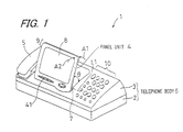
- FIG. 1 is a perspective view showing the appearance of a telephone 1 having a facsimile function according to an embodiment of the invention.
- the telephone 1 as the electronic apparatus includes a lower cabinet 2, an upper cabinet 3, a panel unit 4 as the tilting portion provided on the upper cabinet 3, and a handset 5 hung on a side part of the upper cabinet 3.
- the lower cabinet 2 and the upper cabinet 3 constitute a telephone body 6 as the electronic apparatus body.
- the panel unit 4 has its base end coupled to the upper cabinet 3 on the rear surface side so as to be angularly displaceable about a rotation axis line L1 by a rotary bearing 7 and to be detachably attachable, and by operating a top end 9 of the panel unit 4 with fingers in the direction of the arrow A1 when the panel unit 4 is opened and in the direction of the arrow A2 when the panel unit 4 is closed, a liquid crystal 8 can be set at an easy-to-view angle, that is, the tilt angle ⁇ can be adjusted to the easy-to-view angle with the rotation axis line L1 as the center of the angular displacement.
- the upper cabinet 3 has a telephone key input portion 10 having a plurality of keys for inputting telephone numbers and the like.
- the panel unit 4 has a display key input portion 41 having a plurality of keys for selecting or switching the display mode displayed on a liquid crystal display 8. Since the display key input portion 41 is provided on the panel unit 4, it can be performed to, when the line is connected once, raise the panel unit 4 at a desired tilt angle ⁇ and operate the display key input portion 41 provided on the panel unit 4 while viewing the contents displayed on the liquid crystal display 8. Thus, convenience is improved in viewability and operability.
- FIG. 2 is an exploded perspective view showing the panel unit 4 viewed from the rear surface side, and a neighborhood of the area of the upper cabinet 3 covered when the panel unit 4 is closed.
- FIG. 3 is a perspective view of a frictional member 14 viewed obliquely from below.
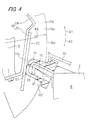
- FIG. 4 is an enlarged cross-sectional view of a neighborhood of the frictional member 14.
- the telephone 1 includes the following as a structure for supplying the panel unit 4 with an optimum tilt holding force: an attachment portion 15 provided on the upper cabinet 3 so as to protrude while facing the panel unit 4; the frictional member 14 made of silicone rubber which is a material having flexibility and elasticity, and detachably attached to the attachment portion 15; and two sliding members 11 and 12 provided on the rear surface of the panel unit 4 which rear surface faces the attachment portion 15, and sliding on the frictional member 14 over the angular displacement range of the panel unit 4.
- the first sliding member 11 comprises a pair of plates 18a and 18b sliding on sides 17a and 17b of the frictional portion 14 over the angular displacement range of the panel unit 4.
- the second sliding member 12 comprises a plate spring 19 for elastically pushing a free end 17c of the frictional member 14 over the angular displacement range of the panel unit 4, and a rough sheet 20 bonded to the plate spring 19 with an adhesive and having a rough sliding surface 20a having a higher sliding frictional force on the frictional member 14 than that of the plate spring 19.
- the rough sheet 20 is implemented, for example, by a rubber mixed with cork powder.
- the rough sheet 20 is provided on the plate spring 19 as described above, a moderate frictional force by the sliding contact between the frictional member 14 and the rough sheet 20 is obtained, the edges of the plate spring 19 on the side that is in contact with the frictional member 14 are never directly in contact with the frictional member 14 because of the presence of the rough sheet 20, and the edges prevent the frictional member 14 from wearing away, so that the durability of the frictional member 14 is improved.
- the plates 18a and 18b of the first sliding member 11 slide on the sides 17a and 17b of the frictional portion 14 over the angular displacement range of the panel unit 4.
- the area of contact with the sides 17a and 17b of the frictional member 14 is decreased as the panel unit 4 is angularly displaced in the opening direction A1 with respect to the telephone body 6, and the area of contact with the sides 17a and 17b of the frictional member 14 is increased as the panel unit 4 is angularly displaced in the closing direction A2 with respect to the telephone body 6.
- the second sliding member 12 elastically pushes the free end 17c of the frictional member 14 over the angular displacement range of the panel unit 4.
- an opening 21 is formed in the area to which the rear surface of the panel unit 4 is opposed when the panel unit 4 is closed, and the attachment portion 15 is provided so as to face the outside from the opening 21.
- concave portions 23a and 23b in which a pair of pins 22a and 22b of the panel unit 4 are fitted are provided in a lower part of the rear surface of the panel unit 4.
- the pins 22a and 22b are integrally formed on both sides of the opening 21 so as to protrude.
- the attachment portion 15 has a protrusion 24 inserted in the frictional member 14, and a latching portion 25 formed integrally with the protrusion 24 so as to bend downward (downward in FIG. 4) from the tip of the protrusion 24.
- an insertion hole 37 allowing the latching portion 25 to pass therethrough is formed so as to be opened downward through an opening 121.
- a rib 36 is provided for preventing the frictional member 14 from being detached when the frictional member 14 is elastically deformed in the angular displacement direction A1 or A2 due to the sliding frictional force caused when the panel unit 4 is angularly displaced in the direction of the arrow A1 or A2.
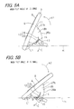
- FIGs. 5A and 5B are views of assistance in explaining tilting of the panel unit 4.
- FIG. 5A shows the held condition of the panel unit 4 when the tilt angle ⁇ is large.
- FIG. 5B shows the held condition of the panel unit 4 when the tilt angle ⁇ is small.
- the frictional member 14 is attached to the attachment portion 15 provided on the telephone body 6, and the sliding member 11 is provided on the rear surface of the panel unit 4.
- the plates 18a and 18b slide on the frictional member 14 in the same direction.
- the plates 18a and 18b receive from the frictional member 14 a frictional force in a direction C opposite to the angular displacement direction A1.
- the frictional member 14 is made of a material having flexibility and elasticity, the frictional member 14 is elastically deformed by the plates 18a and 18b in accordance with the angular displacement direction A1 and the angular displacement position of the panel unit 4, and the area of contact decreases in accordance with the elastic deformation, whereby the frictional force acting on the plates 18a and 18b can be reduced.
- the frictional member 14 elastically pushes the inner surfaces 27a and 27b while being deformed in the direction of movement of the plates 18a and 18b and at this time, the dynamic frictional force is smaller than the static frictional force, so that an appropriate tilt holding force where no shift is caused due to the weight of the panel unit 4 can be obtained with a simple structure.
- the second sliding member 12 includes the plate spring 19 for elastically pushing the free end 17c of the frictional member 14, a plate spring having a spring force appropriate for the weight of the panel unit 4 can be adopted as the plate spring 19, so that a tilt holding force appropriate for the weight of the panel unit 4 can be obtained with a simple structure.
- the frictional member 14 is detachably attached to the attachment portion 15, attachment of the frictional member at the time of manufacture, and attachment and detachment of the frictional member when a worn, deteriorating or damaged frictional member is replaced can be easily performed, so that the productivity and the maintainability of the telephone 1 can be improved.
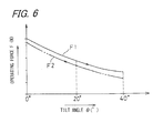
- FIG. 6 is a graph showing a relationship between the tilt angle ⁇ and operating forces F1 and F2 in the angular displacement direction at the top end which forces F1 and F2 are necessary for the angular displacement of the panel unit 4 in the opening direction A1 and in the closing direction A2.
- the inventor of the invention attached a measuring instrument such as a spring balance to the top end of the panel unit 4 which top end was farthest from the rotation axis line L1, an arc-shaped locus along which the top end should move at the time of the angular displacement was assumed, the panel unit 4 was pulled in the direction of the tangent to the locus, and the tensile load caused at that time was measured.
- a measuring instrument such as a spring balance
- This measurement was performed, both when the panel unit 4 was opened and when the panel unit 4 was closed, in the following three positions: when the minimum tilt angle ⁇ where the panel unit 4 was closed with respect to the upper cabinet 3 so as to be substantially horizontal was 0°; when the maximum tilt angle ⁇ where the panel unit 4 was opened with respect to the upper cabinet 3 was 40°; and when a middle tilt angle ⁇ which was the midpoint of the minimum and the maximum tilt angles was 20°.
- the operating force F1 was 5.4 N (approximately 550 gf), when the tilt angle ⁇ was 20°, the operating force F1 was approximately 3.5 N (360 gf), and when the tilt angle ⁇ was 40°, the operating force F1 was approximately 2.6 N (270 gf).
- the operating force F2 was approximately 2.4 N (240 gf)
- the tilt angle ⁇ was 20°
- the operating force F2 was approximately 3.2 N (330 gf)
- the operating force F2 was approximately 5.2 N (530 gf).
- a frictional force can be obtained both in the opening direction A1 and in the closing direction A2 and by the second sliding member 12 comprising the plate spring 19 and the rough sheet 20, a large frictional force can be obtained by increasing the area of contact by elastically deforming a neighborhood of the free end 17c of the frictional member 14 in the closing direction A2, so that the panel unit 4 can be stopped at a desired angle against the increase in the weight of the panel unit 4 with a large resisting force in the closing direction A2, and can be smoothly moved in the closing direction A2 without the need for an unnecessarily large force.
- FIG. 7 is a cross-sectional view of a part of an electronic apparatus 1a according to another embodiment of the invention.
- FIG. 8 is an exploded perspective view of a panel unit 4a of the electronic apparatus 1a viewed from the rear surface side.
- FIG. 9 is a perspective view of the panel unit 4a viewed from the rear surface side.
- the elements corresponding to those of the above-described embodiment are designated by the same reference numerals. While the electronic apparatus 1a of this embodiment is similar to the above-described embodiment in that similar advantages are obtained by a common structure, what is worthy of note is that a plate spring 30 for elastically pushing a free end of a frictional member 14 over the angular displacement range of the panel unit 4a is provided as the second sliding member 12.
- the plate spring 30 has its one end detachably fixed to a back wall of the panel unit 4a with a screw 35.
- the plate spring 30 On the plate spring 30, a plurality of bent portions 31a, 31b and 31c convexly bent outward with respect to the rear surface of the panel unit 4a is formed.
- the plate spring 30 is fitted between plates 18a and 18b.
- the plates 18a and 18b are similar to those of the above-described embodiment in that the plates 18a and 18b elastically sandwich sides 17a and 17b of the frictional member 14 from both sides and that the plate spring 30 elastically pushes the free end 17c of the frictional member 14.
- the frictional member 14 is brought into contact with parts 32a to 32c between the bent portions 31a to 31c of the plate spring 30 to thereby support in multiple steps with a large supporting force the angular displacement of the panel unit 4a in the opening direction A1 and in the closing direction A2, and particularly, an undesired angular displacement of the panel unit 4a in the closing direction A2 due to the weight of the panel unit 4 can be prevented with reliability.
- the panel unit 4 can be angularly displaced with a small operating force both in the opening direction A1 and in the closing direction A2.
- a tilt holding force appropriate for the weight of the tilting portion can be obtained with a simple structure.
- a rubber tube 33 may be attached to the plate spring 30 of the embodiment shown in FIGs. 7 to 9 as shown by the virtual line of FIG. 7.
- the tilting portion may be an apparatus other than the panel unit 4, for example, an operation panel provided with only a plurality of operation keys.
- the electronic apparatus may be an apparatus other than the above-described telephone having a facsimile function, for example, a personal computer.
- the invention can be implemented for controlling tilting of a display panel as the tilting portion.
- only one plate may be provided on the rear surface of the panel unit 4 as the sliding member so as to slide on one side of the frictional member 14, or one plate may be inserted in a notch formed in the center of the free end of the frictional member, so as to be supported from both sides thereof by the frictional member 14.
- only one plate since only one plate is used, the number of parts is reduced, and further, a large sliding frictional force can be obtained by the frictional member being in contact with both surfaces of the plate.
Landscapes
- Engineering & Computer Science (AREA)
- General Engineering & Computer Science (AREA)
- Theoretical Computer Science (AREA)
- Computer Hardware Design (AREA)
- Physics & Mathematics (AREA)
- Human Computer Interaction (AREA)
- General Physics & Mathematics (AREA)
- Signal Processing (AREA)
- Mechanical Engineering (AREA)
- Multimedia (AREA)
- Mathematical Physics (AREA)
- Casings For Electric Apparatus (AREA)
- Telephone Set Structure (AREA)
- Pivots And Pivotal Connections (AREA)
Abstract
Description
Claims (8)
- An electronic apparatus (1, 1a) comprising:an electronic apparatus body (6);a tilting portion (4) provided on the electronic apparatus body (6) so as to be angularly displaceable about a rotation axis line (L1);an attachment portion (15) provided on the electronic apparatus body (6) so as to protrude while facing the tilting portion (4);a frictional member (14) made of a material having flexibility and elasticity, and attached to the attachment portion (15); anda sliding member (11, 12) provided on a rear surface of the tilting portion (4) which rear surface faces the attachment portion (15), for sliding on the frictional member (14) over an angular displacement range of the tilting portion (4).
- The electronic apparatus (1, 1a) of claim 1, wherein the sliding member (11) includes a plate (18a, 18b) for sliding on a side (17a, 17b) of the frictional member (14) over the angular displacement range of the tilting portion (4).
- The electronic apparatus (1, 1a) of claim 1, wherein the sliding member (12) includes a plate spring (19) for elastically pushing a free end (17c) of the frictional member (14) over the angular displacement range of the tilting portion (4).
- The electronic apparatus (1, 1a) of claim 1, wherein the sliding member (11) includes a plate (18a, 18b) for sliding on a side (17a, 17b) of the frictional member (14) over the angular displacement range of the tilting portion (4), an area of contact of the sliding member (11) with the side (17a, 17b) of the frictional member (14) decreases as the tilting portion (4) is angularly displaced in an opening direction (A1) with respect to the electronic apparatus (6), and the area of contact of the sliding member (11) with the side (17a, 17b) of the frictional member (14) increases as the tilting portion (4) is angularly displaced in a closing direction (A2) with respect to the electronic apparatus (6).
- The electronic apparatus (1) of claim 1, wherein the sliding member (12) includes a plate spring (19) for elastically pushing a free end (17c) of the frictional member (14) over the angular displacement range of the tilting portion (4), and the plate spring (19) has a rough sliding surface (20a) having a higher sliding frictional force on the frictional member (14) than that of the plate spring (19).
- The electronic apparatus (1a) of claim 1, wherein the sliding member (12) includes a plate spring (30) for elastically pushing a free end (17c) of the frictional member (14) over the angular displacement range of the tilting portion (4), and on the plate spring (30), a plurality of bent portions (31a, 31b, 31c) convexly bent outward with respect to the rear surface of the tilting portion (4) is formed.
- The electronic apparatus (1, 1a) of any one of claims 1 to 6, wherein the frictional member (14) is detachably attached to the attachment portion (15).
- The electronic apparatus (1, la) of any one of claims 1 to 6, wherein the attachment portion (15) includes a protrusion (24) which is inserted into the frictional member (14) and a latching portion (25) formed integrally with the protrusion (24) so as to bend downward from the tip of the protrusion (24), and the frictional member (14) includes an insertion hole (37) formed so as to be opened downward through an opening (121) to allow the latching portion (25) to pass therethrough and is detachably attached to the attachment portion (15).
Applications Claiming Priority (2)
| Application Number | Priority Date | Filing Date | Title |
|---|---|---|---|
| JP2001303111 | 2001-09-28 | ||
| JP2001303111A JP3934902B2 (en) | 2001-09-28 | 2001-09-28 | Electronics |
Publications (2)
| Publication Number | Publication Date |
|---|---|
| EP1300599A2 true EP1300599A2 (en) | 2003-04-09 |
| EP1300599A3 EP1300599A3 (en) | 2005-11-09 |
Family
ID=19123252
Family Applications (1)
| Application Number | Title | Priority Date | Filing Date |
|---|---|---|---|
| EP02256773A Withdrawn EP1300599A3 (en) | 2001-09-28 | 2002-09-27 | Electronic apparatus |
Country Status (4)
| Country | Link |
|---|---|
| US (1) | US20030061684A1 (en) |
| EP (1) | EP1300599A3 (en) |
| JP (1) | JP3934902B2 (en) |
| CN (1) | CN1410685A (en) |
Cited By (4)
| Publication number | Priority date | Publication date | Assignee | Title |
|---|---|---|---|---|
| EP1832224A1 (en) | 2006-03-09 | 2007-09-12 | Olympus Medical Systems Corp. | Endoscope device and display device |
| EP1930646A3 (en) * | 2006-12-07 | 2009-07-15 | Toshiba Tec Kabushiki Kaisha | Display device |
| EP1736094A4 (en) * | 2004-04-12 | 2010-10-13 | Olympus Corp | Endoscope device |
| EP3540557A4 (en) * | 2016-11-10 | 2019-12-04 | JRD Communication (Shenzhen) Ltd | COMPOSITE TREE ASSEMBLY, MULTIFUNCTION KEYBOARD, AND EXTERNAL COMPONENT OF TABLET COMPUTER |
Families Citing this family (12)
| Publication number | Priority date | Publication date | Assignee | Title |
|---|---|---|---|---|
| KR100542354B1 (en) | 2003-10-13 | 2006-01-10 | 삼성전자주식회사 | Electronic device with improved hinge |
| US20060272129A1 (en) * | 2005-06-04 | 2006-12-07 | Torqmaster, Inc. | Friction hinge with viscous damping |
| JP5250957B2 (en) * | 2006-10-17 | 2013-07-31 | サクサ株式会社 | Display mounting structure |
| JP2008142975A (en) * | 2006-12-07 | 2008-06-26 | Brother Ind Ltd | Cover opening / closing mechanism and printing apparatus provided with the cover opening / closing mechanism |
| JP4834692B2 (en) * | 2008-05-19 | 2011-12-14 | 株式会社日立製作所 | Electronic device with display unit |
| JP5472631B2 (en) * | 2010-07-28 | 2014-04-16 | 岩崎通信機株式会社 | Electronic device with display unit |
| JP5112535B2 (en) * | 2011-05-23 | 2013-01-09 | 株式会社ティ・ケイ・エム | Hinge mechanism |
| CN103133515A (en) * | 2011-11-29 | 2013-06-05 | 致伸科技股份有限公司 | Support device for flip cover |
| JP6932482B2 (en) * | 2016-04-25 | 2021-09-08 | キヤノン株式会社 | Image forming device |
| CN106194984B (en) * | 2016-08-31 | 2019-02-15 | 上海度娃教育科技有限公司 | A kind of self-resetting structure of controllable rotating angle |
| JP2020034011A (en) * | 2018-08-27 | 2020-03-05 | シャープ株式会社 | Hinge device and image forming device |
| JP6773348B1 (en) * | 2019-09-12 | 2020-10-21 | Necプラットフォームズ株式会社 | How to assemble the angle adjustment mechanism, desktop equipment and angle adjustment mechanism |
Family Cites Families (27)
| Publication number | Priority date | Publication date | Assignee | Title |
|---|---|---|---|---|
| US588642A (en) * | 1897-08-24 | Hinge | ||
| US3237239A (en) * | 1963-08-30 | 1966-03-01 | Rudnick Jack | Hinge structure |
| US3608130A (en) * | 1965-09-22 | 1971-09-28 | Paniflex Corp | Hinge device |
| US4114236A (en) * | 1977-07-28 | 1978-09-19 | Minnesota Mining & Manufacturing Company | Hinge structure for platen covers |
| DE2828052C2 (en) * | 1978-06-26 | 1983-06-01 | Karl Lautenschläger KG, Möbelbeschlagfabrik, 6107 Reinheim | Latch hinge |
| US4287641A (en) * | 1979-08-20 | 1981-09-08 | Masco Corporation | Self-closing hinge |
| DE3218804A1 (en) * | 1982-05-18 | 1983-11-24 | Alfred Grass GmbH Metallwarenfabrik, 6973 Höchst, Vorarlberg | SINGLE-JOINT DOOR HINGE WITH CLOSING AND, IF NECESSARY, OPEN-PRESSURE DEVICE |
| US4800624A (en) * | 1985-05-21 | 1989-01-31 | Ford Motor Company | Hinge with elastomerically supported check spring |
| US4730364A (en) * | 1985-10-29 | 1988-03-15 | Bondwell Holding Ltd. | Data processor flush hinge assembly |
| US5196993A (en) * | 1989-03-06 | 1993-03-23 | Unisys Corp. | Removable stand alone display for laptop computer |
| US4962567A (en) * | 1989-07-13 | 1990-10-16 | Wilbur Dixon | Butt hinge assembly |
| US4993772A (en) * | 1990-02-20 | 1991-02-19 | Irvin Automotive Products, Inc. | Spring-loaded, dual-action hinge assembly for vehicle accessories |
| US5027474A (en) * | 1990-08-30 | 1991-07-02 | Amerock Corporation | Concealed self-closing hinge with leaf spring |
| US5109573A (en) * | 1990-09-27 | 1992-05-05 | Smith Corona Corporation | Brake mechanism for a pivotable character display |
| CA2059860C (en) * | 1992-01-22 | 1996-09-10 | Beverley W. Gumb | Telephone base |
| US5413317A (en) * | 1993-04-22 | 1995-05-09 | Prince Corporation | Damping device |
| US5355557A (en) * | 1993-05-18 | 1994-10-18 | Amerock Corporation | Concealed self-closing hinge with integral hinge pin means |
| EP0731430B1 (en) * | 1995-03-10 | 2000-07-19 | Toshiba Tec Kabushiki Kaisha | Sales-registration-data processing apparatus |
| GB9613079D0 (en) * | 1996-06-21 | 1996-08-28 | Mangar International Ltd | Lifting apparatus |
| US5867871A (en) * | 1997-11-11 | 1999-02-09 | Tasman; Randy | Outwardly swinging shower door hinge having a concealed knuckle |
| JP4140932B2 (en) * | 1998-02-06 | 2008-08-27 | 松下電器産業株式会社 | Display attitude setting device and information terminal device provided with the display attitude setting device |
| US6019338A (en) * | 1998-02-23 | 2000-02-01 | Nortel Networks Corporation | Tilt stand for desktop terminal |
| DE29816727U1 (en) * | 1998-09-17 | 1998-12-24 | Salice Arturo Spa | hinge |
| US6226835B1 (en) * | 1999-09-10 | 2001-05-08 | Newell Operating Company | Hinge |
| US6470532B2 (en) * | 2000-02-29 | 2002-10-29 | Torqmaster, Inc. | Cam hinge with controlled friction for improved cam operation |
| US6351373B1 (en) * | 2000-05-02 | 2002-02-26 | Gateway, Inc. | Cam and hinge mechanism for angular insertion |
| US6523185B1 (en) * | 2001-11-27 | 2003-02-25 | Randolph J. Moore | Self-lowering toilet seat |
-
2001
- 2001-09-28 JP JP2001303111A patent/JP3934902B2/en not_active Expired - Fee Related
-
2002
- 2002-09-27 EP EP02256773A patent/EP1300599A3/en not_active Withdrawn
- 2002-09-27 US US10/255,629 patent/US20030061684A1/en not_active Abandoned
- 2002-09-28 CN CN02149516.5A patent/CN1410685A/en active Pending
Cited By (8)
| Publication number | Priority date | Publication date | Assignee | Title |
|---|---|---|---|---|
| EP1736094A4 (en) * | 2004-04-12 | 2010-10-13 | Olympus Corp | Endoscope device |
| EP1832224A1 (en) | 2006-03-09 | 2007-09-12 | Olympus Medical Systems Corp. | Endoscope device and display device |
| US8033993B2 (en) | 2006-03-09 | 2011-10-11 | Olympus Medical Systems Corp. | Endoscope device and display device |
| EP1930646A3 (en) * | 2006-12-07 | 2009-07-15 | Toshiba Tec Kabushiki Kaisha | Display device |
| US7660106B2 (en) | 2006-12-07 | 2010-02-09 | Toshiba Tec Kabushiki Kaisha | Display device |
| US7957129B2 (en) | 2006-12-07 | 2011-06-07 | Toshiba Tec Kabushiki Kaisha | Display device |
| EP3540557A4 (en) * | 2016-11-10 | 2019-12-04 | JRD Communication (Shenzhen) Ltd | COMPOSITE TREE ASSEMBLY, MULTIFUNCTION KEYBOARD, AND EXTERNAL COMPONENT OF TABLET COMPUTER |
| US11042197B2 (en) | 2016-11-10 | 2021-06-22 | Jrd Communication (Shenzhen) Ltd | Composite hinge assembly, multi-functional keypad and tablet computer kit |
Also Published As
| Publication number | Publication date |
|---|---|
| CN1410685A (en) | 2003-04-16 |
| US20030061684A1 (en) | 2003-04-03 |
| JP3934902B2 (en) | 2007-06-20 |
| EP1300599A3 (en) | 2005-11-09 |
| JP2003110248A (en) | 2003-04-11 |
Similar Documents
| Publication | Publication Date | Title |
|---|---|---|
| EP1300599A2 (en) | Electronic apparatus | |
| US6587333B2 (en) | Flat panel display apparatus and tilt/swivel mechanism therein | |
| EP1450545B1 (en) | Portable terminal | |
| US6781821B2 (en) | Electronic apparatus | |
| US10989987B2 (en) | Electronic apparatus | |
| US9047043B2 (en) | Electronic apparatus | |
| US8031463B2 (en) | Electronic apparatus emitting light through a unitary transparent base chassis | |
| US6778196B2 (en) | Mounting a display panel in a computer | |
| US7478789B2 (en) | Pivoting mechanism for stand and electronic apparatus | |
| US7064745B2 (en) | Rotary-keypad for a mobile handset | |
| US20060252471A1 (en) | Tilting and sliding mobile device | |
| US20080174942A1 (en) | Handheld Electronic Device | |
| US20110102982A1 (en) | Electronic apparatus | |
| CN101854409B (en) | Information terminal device | |
| EP1278354B1 (en) | Telephone with cantilever beam type cradle and handset cradled thereon | |
| KR101756141B1 (en) | Slim Type Tilting Hinge and Electric Device having it | |
| US20250278125A1 (en) | Electronic apparatus and slide mechanism | |
| KR20120026268A (en) | Slide-tilt hinge device for mobile phone | |
| JP2003167666A (en) | Portable electronic devices | |
| CN100472668C (en) | Tilt adjustment device for LCD display using rails | |
| KR101153372B1 (en) | Slide-tilt hinge device for mobile terminal | |
| JP5730600B2 (en) | Portable electronic devices | |
| JP2000316115A (en) | Moving part connecting mechanism, electronic equipment and imaging apparatus using the moving part connecting mechanism |
Legal Events
| Date | Code | Title | Description |
|---|---|---|---|
| PUAI | Public reference made under article 153(3) epc to a published international application that has entered the european phase |
Free format text: ORIGINAL CODE: 0009012 |
|
| AK | Designated contracting states |
Kind code of ref document: A2 Designated state(s): AT BE BG CH CY CZ DE DK EE ES FI FR GB GR IE IT LI LU MC NL PT SE SK TR Designated state(s): AT BE BG CH CY CZ DE DK EE ES FI FR GB GR IE IT LI LU MC NL PT SE SK TR |
|
| AX | Request for extension of the european patent |
Extension state: AL LT LV MK RO SI |
|
| PUAL | Search report despatched |
Free format text: ORIGINAL CODE: 0009013 |
|
| AK | Designated contracting states |
Kind code of ref document: A3 Designated state(s): AT BE BG CH CY CZ DE DK EE ES FI FR GB GR IE IT LI LU MC NL PT SE SK TR |
|
| AX | Request for extension of the european patent |
Extension state: AL LT LV MK RO SI |
|
| AKX | Designation fees paid | ||
| REG | Reference to a national code |
Ref country code: DE Ref legal event code: 8566 |
|
| STAA | Information on the status of an ep patent application or granted ep patent |
Free format text: STATUS: THE APPLICATION IS DEEMED TO BE WITHDRAWN |
|
| 18D | Application deemed to be withdrawn |
Effective date: 20060510 |