EP1300567A2 - Bleed deflector for a gas turbine - Google Patents
Bleed deflector for a gas turbine Download PDFInfo
- Publication number
- EP1300567A2 EP1300567A2 EP02256189A EP02256189A EP1300567A2 EP 1300567 A2 EP1300567 A2 EP 1300567A2 EP 02256189 A EP02256189 A EP 02256189A EP 02256189 A EP02256189 A EP 02256189A EP 1300567 A2 EP1300567 A2 EP 1300567A2
- Authority
- EP
- European Patent Office
- Prior art keywords
- bleed
- duct
- deflector according
- top plate
- air
- Prior art date
- Legal status (The legal status is an assumption and is not a legal conclusion. Google has not performed a legal analysis and makes no representation as to the accuracy of the status listed.)
- Granted
Links
- 238000010790 dilution Methods 0.000 claims abstract description 5
- 239000012895 dilution Substances 0.000 claims abstract description 5
- 238000007599 discharging Methods 0.000 claims abstract description 4
- 230000003116 impacting effect Effects 0.000 claims description 2
- 230000001419 dependent effect Effects 0.000 claims 1
- 230000003584 silencer Effects 0.000 description 4
- 238000012986 modification Methods 0.000 description 2
- 230000004048 modification Effects 0.000 description 2
- 230000009286 beneficial effect Effects 0.000 description 1
- 239000002131 composite material Substances 0.000 description 1
- 239000000463 material Substances 0.000 description 1
- 230000008447 perception Effects 0.000 description 1
- 238000001228 spectrum Methods 0.000 description 1
Images


Classifications
-
- F—MECHANICAL ENGINEERING; LIGHTING; HEATING; WEAPONS; BLASTING
- F02—COMBUSTION ENGINES; HOT-GAS OR COMBUSTION-PRODUCT ENGINE PLANTS
- F02C—GAS-TURBINE PLANTS; AIR INTAKES FOR JET-PROPULSION PLANTS; CONTROLLING FUEL SUPPLY IN AIR-BREATHING JET-PROPULSION PLANTS
- F02C9/00—Controlling gas-turbine plants; Controlling fuel supply in air- breathing jet-propulsion plants
- F02C9/16—Control of working fluid flow
- F02C9/18—Control of working fluid flow by bleeding, bypassing or acting on variable working fluid interconnections between turbines or compressors or their stages
-
- F—MECHANICAL ENGINEERING; LIGHTING; HEATING; WEAPONS; BLASTING
- F01—MACHINES OR ENGINES IN GENERAL; ENGINE PLANTS IN GENERAL; STEAM ENGINES
- F01D—NON-POSITIVE DISPLACEMENT MACHINES OR ENGINES, e.g. STEAM TURBINES
- F01D9/00—Stators
- F01D9/06—Fluid supply conduits to nozzles or the like
- F01D9/065—Fluid supply or removal conduits traversing the working fluid flow, e.g. for lubrication-, cooling-, or sealing fluids
-
- F—MECHANICAL ENGINEERING; LIGHTING; HEATING; WEAPONS; BLASTING
- F02—COMBUSTION ENGINES; HOT-GAS OR COMBUSTION-PRODUCT ENGINE PLANTS
- F02K—JET-PROPULSION PLANTS
- F02K3/00—Plants including a gas turbine driving a compressor or a ducted fan
- F02K3/02—Plants including a gas turbine driving a compressor or a ducted fan in which part of the working fluid by-passes the turbine and combustion chamber
- F02K3/04—Plants including a gas turbine driving a compressor or a ducted fan in which part of the working fluid by-passes the turbine and combustion chamber the plant including ducted fans, i.e. fans with high volume, low pressure outputs, for augmenting the jet thrust, e.g. of double-flow type
- F02K3/075—Plants including a gas turbine driving a compressor or a ducted fan in which part of the working fluid by-passes the turbine and combustion chamber the plant including ducted fans, i.e. fans with high volume, low pressure outputs, for augmenting the jet thrust, e.g. of double-flow type controlling flow ratio between flows
-
- Y—GENERAL TAGGING OF NEW TECHNOLOGICAL DEVELOPMENTS; GENERAL TAGGING OF CROSS-SECTIONAL TECHNOLOGIES SPANNING OVER SEVERAL SECTIONS OF THE IPC; TECHNICAL SUBJECTS COVERED BY FORMER USPC CROSS-REFERENCE ART COLLECTIONS [XRACs] AND DIGESTS
- Y10—TECHNICAL SUBJECTS COVERED BY FORMER USPC
- Y10S—TECHNICAL SUBJECTS COVERED BY FORMER USPC CROSS-REFERENCE ART COLLECTIONS [XRACs] AND DIGESTS
- Y10S415/00—Rotary kinetic fluid motors or pumps
- Y10S415/914—Device to control boundary layer
Definitions
- the present invention relates to a bleed deflector for use in a gas turbine engine.
- Typical bleed discharge air is up to 800°F to 1000°F (427-538°C), while fan air is up to 240°F (120°C).
- Duct material temperature limits are on the order of 300°F to 350°F (149°-177°C).
- the Bryce silencer includes a flow passage and a domed perforated plate which terminates the flow passage.
- the perforated portions of the plate are distributed over the plate so as to direct gas from the passage as a plurality of divergent jets, so that noise is produced with a frequency at maximum intensity in a range of the audible spectrum at which human auditory perception is relatively insensitive.
- the domed plate portion of the silencer is mounted flush with the inner wall of the bypass duct.
- FIGS. 1 and 2 An aerodynamically shaped deflector 10 has outlets 12 in its side walls which separate the bleed air discharge into two lateral plumes 14 and 16. Each of the outlets 12 has discrete holes which can be angled to direct the jets in a desired direction. This deflector however did not work because it was not possible to jet enough flow out of the bleed deflector. Thus, there remains a need for a bleed deflector which adequately discharges the bleed air from a compressor of a gas turbine engine.
- a bleed deflector broadly comprises an inlet portion for receiving bleed air, an outlet portion for discharging the bleed air into a duct, and means for positioning said outlet portion above an inner wall of the duct and for creating a linear flow path for the discharge air between the inlet portion and the outlet portion.
- the bleed deflector 20 has an inlet portion 22 for receiving bleed air from a compressor stage (not shown) of a gas turbine engine.
- the bleed deflector 20 further has an outlet portion 24 and a member 26 for positioning the outlet portion 24 above an inner wall 28 of a fan duct 30.
- the positioning member 26 is aerodynamically shaped to minimize drag and to allow for a maximum amount of dilution air, generated by the engine fan (not shown), beneath the outlet portion 24. This eliminates contact of the hot bleed gasses with the duct inner wall 28 during low and high power operation of the engine, or should the bleed valve (not shown) leak.
- the positioning member 26 comprises a strut having a leading edge 32, a trailing edge 34, and arcuately shaped, non-linear, side surfaces 36 and 38 each extending between the leading edge 32 and the trailing edge 34. Further, the positioning member 26 has a height h sufficient to insure that the plume 27 from the outlet portion 24 does not contact the inner wall 28.
- the outlet portion 24 includes a base portion 40 integrally formed with or joined to the upper end of the positioning member 26.
- the base portion 40 is arcuately curved along its lower surface 42 to further improve the air flow within the duct 30.
- the outlet portion 24 further includes a dome shaped perforated top plate 44 through which the bleed air is discharged into the duct 30.
- the perforated top plate 44 includes a plurality of discrete holes 46. Each hole 46 is sized to prevent the bleed air discharge from contacting the outer wall 48 of the fan duct 30. Further, each hole 46 is not perpendicular to the surface of the perforated top plate 44. Instead, each hole 46 is angled to enhance turning of the exhaust plume 27 in a circumferential direction when looking from the front or rear of the engine.
- the interior shape of the side surfaces 36 and 38, as shown in FIGS. 6 and 7, is such that the bleed air is fed to all of the holes 46.
- the perforated top plate 44 has been found to be useful in diffusing the bleed air as it travels from the inlet portion 22 to the outlet portion 24.
- the perforated top plate 44 also distributes the hot bleed discharge gasses over an area that produces an optimum plume shape and size.
- the bleed deflector of the present invention has particular utility with composite nacelles because such nacelles burn much more easily than metallic nacelles.
- the bleed deflector of the present invention is quite beneficial during idle times when compressor bleed discharge temperature is quite hot.
Landscapes
- Engineering & Computer Science (AREA)
- Mechanical Engineering (AREA)
- General Engineering & Computer Science (AREA)
- Chemical & Material Sciences (AREA)
- Combustion & Propulsion (AREA)
- Physics & Mathematics (AREA)
- Fluid Mechanics (AREA)
- Structures Of Non-Positive Displacement Pumps (AREA)
Abstract
Description
- The present invention relates to a bleed deflector for use in a gas turbine engine.
- Current high pressure compressor bleed discharge designs consist of either a tube or a vaned deflector which directs high temperature engine bleed air into a fan duct. Such an arrangement often leads to structural problems caused by the bleed air plume impacting the inner and outer fan duct walls, exceeding their temperature limits. Typical bleed discharge air is up to 800°F to 1000°F (427-538°C), while fan air is up to 240°F (120°C). Duct material temperature limits are on the order of 300°F to 350°F (149°-177°C).
- In the past, a silencer for high velocity gas flow in a gas turbine engine has been proposed. One such silencer is shown in U.S. Patent No. 4,537,277 to Bryce. As shown therein, the Bryce silencer includes a flow passage and a domed perforated plate which terminates the flow passage. The perforated portions of the plate are distributed over the plate so as to direct gas from the passage as a plurality of divergent jets, so that noise is produced with a frequency at maximum intensity in a range of the audible spectrum at which human auditory perception is relatively insensitive. The domed plate portion of the silencer is mounted flush with the inner wall of the bypass duct.
- It has been found that devices which utilize flush outlets cause inner duct wall burns because cooler fan air cannot get immediately downstream of the outlet to dilute the hot discharge flow from the device.
- Attempts have been made to develop a bleed deflector which avoided the problem of inner duct wall burns. One such attempt is shown in FIGS. 1 and 2. In this bleed deflector, an aerodynamically
shaped deflector 10 hasoutlets 12 in its side walls which separate the bleed air discharge into twolateral plumes outlets 12 has discrete holes which can be angled to direct the jets in a desired direction. This deflector however did not work because it was not possible to jet enough flow out of the bleed deflector. Thus, there remains a need for a bleed deflector which adequately discharges the bleed air from a compressor of a gas turbine engine. - Accordingly, it is an object of the present invention in preferred embodiments at least to provide an improved bleed deflector for use in a gas turbine engine.
- It is a further object of the present invention in preferred embodiments at least to provide a bleed deflector which substantially eliminates wall burns in a fan duct.
- In accordance with the present invention, a bleed deflector broadly comprises an inlet portion for receiving bleed air, an outlet portion for discharging the bleed air into a duct, and means for positioning said outlet portion above an inner wall of the duct and for creating a linear flow path for the discharge air between the inlet portion and the outlet portion.
- Other details of the bleed deflector of the present invention, as well as other advantages attendant thereto, are set forth in the following detailed description and the accompanying drawings wherein like reference numerals depict like elements.
-
- FIG. 1 is a perspective view of a prior art bleed deflector.
- FIG. 2 is a fan duct cross section showing the prior art bleed deflector positioned within a fan duct.
- FIG. 3 is a perspective view of a bleed deflector in accordance with the present invention.
- FIG. 4 is a plan view of the bleed deflector of FIG. 2 installed within a fan duct.
- FIG. 5 is a fan duct cross section showing the bleed deflector of the present invention.
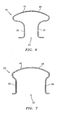
- FIG. 6 is a sectional view of the bleed deflector of FIG. 3 taken along a plane extending from one side to another side of the bleed deflector.
- FIG. 7 is a sectional view of the bleed deflector of FIG. 3 taken along a plane extending from a leading edge of the bleed deflector to a trailing edge of the bleed deflector.
-
- Referring now to FIGS. 3 through 7, a
bleed deflector 20 in accordance with the present invention is illustrated. Thebleed deflector 20 has aninlet portion 22 for receiving bleed air from a compressor stage (not shown) of a gas turbine engine. Thebleed deflector 20 further has anoutlet portion 24 and amember 26 for positioning theoutlet portion 24 above aninner wall 28 of afan duct 30. - The
positioning member 26 is aerodynamically shaped to minimize drag and to allow for a maximum amount of dilution air, generated by the engine fan (not shown), beneath theoutlet portion 24. This eliminates contact of the hot bleed gasses with the ductinner wall 28 during low and high power operation of the engine, or should the bleed valve (not shown) leak. - As can be seen from FIGS. 3 - 5, the
positioning member 26 comprises a strut having a leadingedge 32, atrailing edge 34, and arcuately shaped, non-linear,side surfaces edge 32 and thetrailing edge 34. Further, thepositioning member 26 has a height h sufficient to insure that theplume 27 from theoutlet portion 24 does not contact theinner wall 28. - The
outlet portion 24 includes abase portion 40 integrally formed with or joined to the upper end of thepositioning member 26. Thebase portion 40 is arcuately curved along itslower surface 42 to further improve the air flow within theduct 30. - The
outlet portion 24 further includes a dome shaped perforatedtop plate 44 through which the bleed air is discharged into theduct 30. The perforatedtop plate 44 includes a plurality ofdiscrete holes 46. Eachhole 46 is sized to prevent the bleed air discharge from contacting theouter wall 48 of thefan duct 30. Further, eachhole 46 is not perpendicular to the surface of the perforatedtop plate 44. Instead, eachhole 46 is angled to enhance turning of theexhaust plume 27 in a circumferential direction when looking from the front or rear of the engine. The interior shape of theside surfaces holes 46. - The perforated
top plate 44 has been found to be useful in diffusing the bleed air as it travels from theinlet portion 22 to theoutlet portion 24. The perforatedtop plate 44 also distributes the hot bleed discharge gasses over an area that produces an optimum plume shape and size. - The bleed deflector of the present invention has particular utility with composite nacelles because such nacelles burn much more easily than metallic nacelles. The bleed deflector of the present invention is quite beneficial during idle times when compressor bleed discharge temperature is quite hot.
- It is apparent that there has been provided in accordance with the present invention a bleed deflector for a gas turbine engine which fully satisfies the objects, means, and advantages set forth hereinbefore. While the present invention has been described in the context of specific embodiments thereof, other alternatives, modifications, and variations will become apparent to those skilled in the art having read the foregoing description. Therefore, it is intended to embrace those alternatives, modifications, and variations as fall within the broad scope of the appended claims.
Claims (14)
- A bleed deflector (20) for a gas turbine engine comprising:an inlet portion (22) for receiving bleed air from said engine;outlet means (24) for discharging bleed air into a duct (30) ;means (26) for positioning said outlet means (24) above an inner wall (28) of said duct and for creating a flow path between said inlet portion (22) and said outlet means (24); andsaid outlet means (24) being positioned on top of said positioning means (26).
- A bleed deflector according to claim 1, wherein said positioning means (26) comprises means for minimizing drag and for providing a maximum amount of dilution air under said outlet means.
- A bleed deflector according to claim 2, wherein said drag minimizing and dilution air providing means comprises an aerodynamically shaped strut (26) extending between said inlet portion (22) and said outlet means (24).
- A bleed deflector according to any preceding claim, wherein said outlet means (24) comprises means for separating said bleed discharge into a plurality of discrete plumes elevated from said duct inner wall (28).
- A bleed deflector according to claim 4, wherein said bleed discharge separating means comprises a perforated top plate (44) having a plurality of openings (46).
- A bleed deflector according to claim 5, wherein each of said openings (46) is angled to enhance turning of said bleed air to form said plumes.
- A bleed deflector according to claim 5 or 6, wherein each said opening (46) is sized to prevent said bleed air exiting from said outlet means (24) from impacting and burning an outer (48) and said inner wall (28) of said duct (30).
- A bleed deflector (20) for a gas turbine engine comprising:an inlet portion (22) for receiving bleed air from a portion of said engine;a perforated top plate (44) for discharging said bleed air into a duct (30) ;said perforated top plate (44) being substantially axially aligned with said inlet portion (22); anda strut (26) connected to said inlet portion (22) for positioning said perforated top plate (44) above an inner wall (28) of said duct (30).
- A bleed deflector according to any of claims 5 to 8, wherein said top plate (44) is dome shaped.
- A bleed deflector according to any of claims 5 to 9, wherein said top plate (44) has a plurality of openings (46), each of said openings (46) being angled to create at least one plume of discharge air within said duct (30).
- A bleed deflector according to claim 10, wherein each said opening (46) is sized to prevent said at least one plume from contacting an outer wall of said duct.
- A bleed deflector according to any of claims 5 to 11, wherein a or said strut (26) positions said perforated top plate (44) at a height above the inner wall (28) so that dilution air can flow beneath said perforated top plate (44).
- A bleed deflector according to any of claims 8 to 12, claim 3 or any of claims 4 to 7 as dependent directly or indirectly upon claim 3, wherein said strut (26) has a leading edge (32), a trailing edge (34), and two aerodynamically shaped side surfaces (36, 38) extending between said leading edge (32) and said trailing edge (34).
- A bleed deflector according to claim 13, wherein each of said side surfaces (36, 38) is non-linear.
Applications Claiming Priority (2)
| Application Number | Priority Date | Filing Date | Title |
|---|---|---|---|
| US971404 | 2001-10-04 | ||
| US09/971,404 US6565313B2 (en) | 2001-10-04 | 2001-10-04 | Bleed deflector for a gas turbine engine |
Publications (3)
| Publication Number | Publication Date |
|---|---|
| EP1300567A2 true EP1300567A2 (en) | 2003-04-09 |
| EP1300567A3 EP1300567A3 (en) | 2006-11-02 |
| EP1300567B1 EP1300567B1 (en) | 2012-03-14 |
Family
ID=25518338
Family Applications (1)
| Application Number | Title | Priority Date | Filing Date |
|---|---|---|---|
| EP02256189A Expired - Lifetime EP1300567B1 (en) | 2001-10-04 | 2002-09-06 | Bleed deflector for a gas turbine |
Country Status (3)
| Country | Link |
|---|---|
| US (1) | US6565313B2 (en) |
| EP (1) | EP1300567B1 (en) |
| JP (1) | JP3851252B2 (en) |
Cited By (11)
| Publication number | Priority date | Publication date | Assignee | Title |
|---|---|---|---|---|
| WO2006091142A1 (en) | 2005-02-25 | 2006-08-31 | Volvo Aero Corporation | A bleed structure for a bleed passage in a gas turbine engine |
| EP1775477A2 (en) | 2005-10-17 | 2007-04-18 | Honeywell International Inc. | Bleed valve outlet flow deflector |
| EP1870580A2 (en) | 2006-06-19 | 2007-12-26 | United Technologies Corporation | Slotted bleed deflector for a gas turbine engine |
| EP1900924A3 (en) * | 2006-09-06 | 2008-04-16 | Honeywell International, Inc. | Bleed valve outlet flow deflector |
| US7921652B2 (en) | 2006-07-20 | 2011-04-12 | Rolls-Royce Plc | Aeroengine bleed valve |
| US8128347B2 (en) | 2006-08-25 | 2012-03-06 | Rolls-Royce Plc | Aeroengine bleed valve |
| EP1698774A3 (en) * | 2005-03-02 | 2012-11-21 | Rolls-Royce Plc | A turbine engine and a method of operating a turbine engine |
| US8516827B2 (en) | 2008-01-25 | 2013-08-27 | Rolls-Royce Plc | Aeroengine bleed valve |
| EP2383453A3 (en) * | 2010-04-30 | 2014-04-30 | General Electric Company | Flow mixing vent system |
| EP2431591A3 (en) * | 2010-09-21 | 2015-08-12 | Rolls-Royce plc | Bleed valve |
| FR3087840A1 (en) * | 2018-10-29 | 2020-05-01 | Safran Aircraft Engines | NACELLE HOOD FOR POWERED AIRCRAFT ASSEMBLY |
Families Citing this family (30)
| Publication number | Priority date | Publication date | Assignee | Title |
|---|---|---|---|---|
| US7415827B2 (en) * | 2005-05-18 | 2008-08-26 | United Technologies Corporation | Arrangement for controlling fluid jets injected into a fluid stream |
| US7946104B2 (en) * | 2006-05-12 | 2011-05-24 | Rohr, Inc. | Bleed air relief system for engines |
| US20080044273A1 (en) * | 2006-08-15 | 2008-02-21 | Syed Arif Khalid | Turbomachine with reduced leakage penalties in pressure change and efficiency |
| US20080046407A1 (en) * | 2006-08-16 | 2008-02-21 | Microsoft Corporation | Application search interface |
| US20090016871A1 (en) * | 2007-07-10 | 2009-01-15 | United Technologies Corp. | Systems and Methods Involving Variable Vanes |
| US8029234B2 (en) * | 2007-07-24 | 2011-10-04 | United Technologies Corp. | Systems and methods involving aerodynamic struts |
| US20090126194A1 (en) * | 2007-11-21 | 2009-05-21 | Honeywell International, Inc. | Noise attenuators and methods of manufacturing noise attenuators and bleed valve assemblies |
| US8197209B2 (en) * | 2007-12-19 | 2012-06-12 | United Technologies Corp. | Systems and methods involving variable throat area vanes |
| GB2468669C (en) * | 2009-03-17 | 2013-11-13 | Rolls Royce Plc | A flow discharge device |
| GB0912171D0 (en) * | 2009-07-14 | 2009-08-26 | Rolls Royce Plc | A flow discharge device |
| GB0922425D0 (en) * | 2009-12-23 | 2010-02-03 | Rolls Royce Plc | Bleed assembly for a gas turbine engine |
| DE102010027587A1 (en) * | 2010-07-19 | 2012-01-19 | Rolls-Royce Deutschland Ltd & Co Kg | Bleed air outlet in the bypass duct of a turbofan engine |
| US8430202B1 (en) * | 2011-12-28 | 2013-04-30 | General Electric Company | Compact high-pressure exhaust muffling devices |
| US8511096B1 (en) | 2012-04-17 | 2013-08-20 | General Electric Company | High bleed flow muffling system |
| US9399951B2 (en) | 2012-04-17 | 2016-07-26 | General Electric Company | Modular louver system |
| US8550208B1 (en) | 2012-04-23 | 2013-10-08 | General Electric Company | High pressure muffling devices |
| US9366185B2 (en) | 2012-09-28 | 2016-06-14 | United Technologies Corporation | Flexible connection between a wall and a case of a turbine engine |
| GB201322833D0 (en) * | 2013-12-23 | 2014-02-12 | Rolls Royce Plc | |
| EP3108130B1 (en) * | 2014-02-19 | 2018-12-12 | United Technologies Corporation | Gas turbine engine having minimum cooling airflow |
| GB201408543D0 (en) * | 2014-05-14 | 2014-06-25 | Rolls Royce Plc | Distributor device for cooling air within an engine |
| FR3085438B1 (en) * | 2018-08-30 | 2021-01-22 | Safran Aircraft Engines | HOT GAS EJECTION MOUTH THROUGH AN AIRCRAFT ENGINE WALL |
| US11078837B2 (en) * | 2019-02-06 | 2021-08-03 | Raytheon Technologies Corporation | Engine bleed air ducting into heat exchanger |
| FR3109174B1 (en) * | 2020-04-10 | 2022-04-22 | Safran Aircraft Engines | Acoustically optimized channeled discharge duct grille |
| CN115788673B (en) * | 2021-09-10 | 2026-01-23 | 中国航发商用航空发动机有限责任公司 | Core engine of aeroengine and aeroengine |
| CN113982707A (en) * | 2021-11-04 | 2022-01-28 | 中国航发沈阳黎明航空发动机有限责任公司 | Aeroengine unloading cavity exhaust steering support plate |
| US12366202B2 (en) | 2022-01-18 | 2025-07-22 | General Electric Company | Bleed valve assemblies |
| US12320259B2 (en) | 2022-06-27 | 2025-06-03 | General Electric Company | Compact bleed valve assemblies |
| US11970969B2 (en) * | 2022-06-29 | 2024-04-30 | General Electric Company | Compressor bypass bleed system for a ducted fan engine |
| US12049845B2 (en) | 2022-08-09 | 2024-07-30 | General Electric Company | Variable bleed valves with struts for aerodynamic stability |
| US12180890B1 (en) | 2023-06-23 | 2024-12-31 | General Electric Company | Variable bleed valve assemblies |
Family Cites Families (5)
| Publication number | Priority date | Publication date | Assignee | Title |
|---|---|---|---|---|
| US4463552A (en) * | 1981-12-14 | 1984-08-07 | United Technologies Corporation | Combined surge bleed and dust removal system for a fan-jet engine |
| US4537277A (en) | 1982-12-03 | 1985-08-27 | The Secretary Of State For Defence In Her Britannic Majesty's Government Of The United Kingdom Of Great Britain And Northern Ireland | Silencer for high velocity gas flow |
| US5160241A (en) * | 1991-09-09 | 1992-11-03 | General Electric Company | Multi-port air channeling assembly |
| DE69912488T2 (en) * | 1998-02-13 | 2004-08-12 | Pratt & Whitney Canada Corp., Longueuil | gas turbine |
| DE19959596A1 (en) * | 1999-12-10 | 2001-06-13 | Rolls Royce Deutschland | Blow-off valve of a compressor, in particular for a twin-jet aircraft engine |
-
2001
- 2001-10-04 US US09/971,404 patent/US6565313B2/en not_active Expired - Lifetime
-
2002
- 2002-09-06 EP EP02256189A patent/EP1300567B1/en not_active Expired - Lifetime
- 2002-10-03 JP JP2002290990A patent/JP3851252B2/en not_active Expired - Fee Related
Non-Patent Citations (1)
| Title |
|---|
| None |
Cited By (19)
| Publication number | Priority date | Publication date | Assignee | Title |
|---|---|---|---|---|
| WO2006091142A1 (en) | 2005-02-25 | 2006-08-31 | Volvo Aero Corporation | A bleed structure for a bleed passage in a gas turbine engine |
| EP1856398A4 (en) * | 2005-02-25 | 2014-06-11 | Gkn Aerospace Sweden Ab | VENTILATION STRUCTURE FOR VENTILATION PASSAGE IN A GAS TURBINE ENGINE |
| EP1698774A3 (en) * | 2005-03-02 | 2012-11-21 | Rolls-Royce Plc | A turbine engine and a method of operating a turbine engine |
| EP1775477A2 (en) | 2005-10-17 | 2007-04-18 | Honeywell International Inc. | Bleed valve outlet flow deflector |
| EP1775477A3 (en) * | 2005-10-17 | 2008-04-16 | Honeywell International Inc. | Bleed valve outlet flow deflector |
| US7387489B2 (en) | 2005-10-17 | 2008-06-17 | Honeywell International Inc. | Bleed valve outlet flow deflector |
| EP1870580A2 (en) | 2006-06-19 | 2007-12-26 | United Technologies Corporation | Slotted bleed deflector for a gas turbine engine |
| EP1870580A3 (en) * | 2006-06-19 | 2011-01-05 | United Technologies Corporation | Slotted bleed deflector for a gas turbine engine |
| US7921652B2 (en) | 2006-07-20 | 2011-04-12 | Rolls-Royce Plc | Aeroengine bleed valve |
| EP1881161A3 (en) * | 2006-07-20 | 2012-11-28 | Rolls-Royce plc | Aeroengine bleed valve |
| US8128347B2 (en) | 2006-08-25 | 2012-03-06 | Rolls-Royce Plc | Aeroengine bleed valve |
| EP1892399A3 (en) * | 2006-08-25 | 2012-11-28 | Rolls-Royce plc | Aero engine bleed valve |
| US7797945B2 (en) | 2006-09-06 | 2010-09-21 | Honeywell International Inc. | Bleed valve outlet flow deflector |
| EP1900924A3 (en) * | 2006-09-06 | 2008-04-16 | Honeywell International, Inc. | Bleed valve outlet flow deflector |
| US8516827B2 (en) | 2008-01-25 | 2013-08-27 | Rolls-Royce Plc | Aeroengine bleed valve |
| EP2383453A3 (en) * | 2010-04-30 | 2014-04-30 | General Electric Company | Flow mixing vent system |
| EP2431591A3 (en) * | 2010-09-21 | 2015-08-12 | Rolls-Royce plc | Bleed valve |
| US9121465B2 (en) | 2010-09-21 | 2015-09-01 | Rolls-Royce Plc | Bleed outlet structure for a bleed valve |
| FR3087840A1 (en) * | 2018-10-29 | 2020-05-01 | Safran Aircraft Engines | NACELLE HOOD FOR POWERED AIRCRAFT ASSEMBLY |
Also Published As
| Publication number | Publication date |
|---|---|
| JP2003161167A (en) | 2003-06-06 |
| EP1300567A3 (en) | 2006-11-02 |
| US20030068223A1 (en) | 2003-04-10 |
| EP1300567B1 (en) | 2012-03-14 |
| US6565313B2 (en) | 2003-05-20 |
| JP3851252B2 (en) | 2006-11-29 |
Similar Documents
| Publication | Publication Date | Title |
|---|---|---|
| US6565313B2 (en) | Bleed deflector for a gas turbine engine | |
| US4537277A (en) | Silencer for high velocity gas flow | |
| EP1870580B1 (en) | Slotted bleed deflector for a gas turbine engine | |
| US6973771B2 (en) | Diffuser for terrestrial or aviation gas turbine | |
| EP1191214A3 (en) | Exhaust nozzle with stub airfoils | |
| EP0502924B1 (en) | Dual flow turbine engine muffler | |
| CA2534061C (en) | High efficiency fan cooling holes for turbine airfoil | |
| US6505706B2 (en) | Exhaust flow guide for jet noise reduction | |
| US8931284B2 (en) | Flow discharge device | |
| US8430202B1 (en) | Compact high-pressure exhaust muffling devices | |
| CA2392577A1 (en) | Gas turbine stationary blade | |
| CA2333936A1 (en) | Film cooling strip for gas turbine engine combustion chamber | |
| EP1167722A3 (en) | Methods and apparatus for delivering cooling air within gas turbines | |
| EP1507121A3 (en) | Combustor dome assembly of a gas turbine engine having improved deflector plates | |
| EP1818511A2 (en) | Leaned deswirl vanes behind a centrifugal compressor in a gas turbine engine | |
| WO1995019289A1 (en) | Engine exhaust gas deflection system | |
| EP1253379A3 (en) | Methods and apparatus for cooling gas turbine engine combustors | |
| EP0724119A3 (en) | Dome assembly for a gas turbine engine | |
| ES363673A1 (en) | Outlet housing for an axial-flow turbomachine | |
| CA2551539A1 (en) | Gas turbine engine combustor with improved cooling | |
| CA2451318A1 (en) | Method and apparatus to decrease gas turbine engine combustor emissions | |
| WO2002097870A3 (en) | Diffuser and rapid cycle chamber | |
| JP2002242697A (en) | Method and apparatus for supplying air to a turbine engine combustor | |
| CA2528049A1 (en) | Airfoil platform impingement cooling | |
| CA2380914A1 (en) | Gas turbine combustor |
Legal Events
| Date | Code | Title | Description |
|---|---|---|---|
| PUAI | Public reference made under article 153(3) epc to a published international application that has entered the european phase |
Free format text: ORIGINAL CODE: 0009012 |
|
| AK | Designated contracting states |
Designated state(s): AT BE BG CH CY CZ DE DK EE ES FI FR GB GR IE IT LI LU MC NL PT SE SK TR Kind code of ref document: A2 Designated state(s): AT BE BG CH CY CZ DE DK EE ES FI FR GB GR IE IT LI LU MC NL PT SE SK TR |
|
| AX | Request for extension of the european patent |
Extension state: AL LT LV MK RO SI |
|
| PUAL | Search report despatched |
Free format text: ORIGINAL CODE: 0009013 |
|
| AK | Designated contracting states |
Kind code of ref document: A3 Designated state(s): AT BE BG CH CY CZ DE DK EE ES FI FR GB GR IE IT LI LU MC NL PT SE SK TR |
|
| AX | Request for extension of the european patent |
Extension state: AL LT LV MK RO SI |
|
| 17P | Request for examination filed |
Effective date: 20070319 |
|
| AKX | Designation fees paid |
Designated state(s): DE FR GB |
|
| 17Q | First examination report despatched |
Effective date: 20071031 |
|
| GRAP | Despatch of communication of intention to grant a patent |
Free format text: ORIGINAL CODE: EPIDOSNIGR1 |
|
| RIN1 | Information on inventor provided before grant (corrected) |
Inventor name: MIGLIARO, EDWARD F. Inventor name: NIKKANEN, JOHN P. Inventor name: AVIS, THOMAS B. Inventor name: ZYSMAN, STEVEN H. |
|
| GRAS | Grant fee paid |
Free format text: ORIGINAL CODE: EPIDOSNIGR3 |
|
| GRAA | (expected) grant |
Free format text: ORIGINAL CODE: 0009210 |
|
| AK | Designated contracting states |
Kind code of ref document: B1 Designated state(s): DE FR GB |
|
| REG | Reference to a national code |
Ref country code: GB Ref legal event code: FG4D Ref country code: DE Ref legal event code: R081 Ref document number: 60242382 Country of ref document: DE Owner name: UNITED TECHNOLOGIES CORP. (N.D.GES.D. STAATES , US Free format text: FORMER OWNER: UNITED TECHNOLOGIES CORP. (N.D.GES.D. STAATES DELAWARE), HARTFORD, CONN., US |
|
| REG | Reference to a national code |
Ref country code: DE Ref legal event code: R096 Ref document number: 60242382 Country of ref document: DE Effective date: 20120503 |
|
| PLBE | No opposition filed within time limit |
Free format text: ORIGINAL CODE: 0009261 |
|
| STAA | Information on the status of an ep patent application or granted ep patent |
Free format text: STATUS: NO OPPOSITION FILED WITHIN TIME LIMIT |
|
| 26N | No opposition filed |
Effective date: 20121217 |
|
| REG | Reference to a national code |
Ref country code: DE Ref legal event code: R097 Ref document number: 60242382 Country of ref document: DE Effective date: 20121217 |
|
| REG | Reference to a national code |
Ref country code: FR Ref legal event code: ST Effective date: 20130531 |
|
| PG25 | Lapsed in a contracting state [announced via postgrant information from national office to epo] |
Ref country code: FR Free format text: LAPSE BECAUSE OF NON-PAYMENT OF DUE FEES Effective date: 20121001 |
|
| REG | Reference to a national code |
Ref country code: DE Ref legal event code: R082 Ref document number: 60242382 Country of ref document: DE Representative=s name: SCHMITT-NILSON SCHRAUD WAIBEL WOHLFROM PATENTA, DE |
|
| REG | Reference to a national code |
Ref country code: DE Ref legal event code: R082 Ref document number: 60242382 Country of ref document: DE Representative=s name: SCHMITT-NILSON SCHRAUD WAIBEL WOHLFROM PATENTA, DE Ref country code: DE Ref legal event code: R081 Ref document number: 60242382 Country of ref document: DE Owner name: UNITED TECHNOLOGIES CORP. (N.D.GES.D. STAATES , US Free format text: FORMER OWNER: UNITED TECHNOLOGIES CORPORATION, HARTFORD, CONN., US |
|
| PGFP | Annual fee paid to national office [announced via postgrant information from national office to epo] |
Ref country code: DE Payment date: 20190820 Year of fee payment: 18 |
|
| PGFP | Annual fee paid to national office [announced via postgrant information from national office to epo] |
Ref country code: GB Payment date: 20190820 Year of fee payment: 18 |
|
| REG | Reference to a national code |
Ref country code: DE Ref legal event code: R119 Ref document number: 60242382 Country of ref document: DE |
|
| GBPC | Gb: european patent ceased through non-payment of renewal fee |
Effective date: 20200906 |
|
| PG25 | Lapsed in a contracting state [announced via postgrant information from national office to epo] |
Ref country code: DE Free format text: LAPSE BECAUSE OF NON-PAYMENT OF DUE FEES Effective date: 20210401 |
|
| PG25 | Lapsed in a contracting state [announced via postgrant information from national office to epo] |
Ref country code: GB Free format text: LAPSE BECAUSE OF NON-PAYMENT OF DUE FEES Effective date: 20200906 |