EP1300557A2 - Schaltsaugrohr - Google Patents
Schaltsaugrohr Download PDFInfo
- Publication number
- EP1300557A2 EP1300557A2 EP02022012A EP02022012A EP1300557A2 EP 1300557 A2 EP1300557 A2 EP 1300557A2 EP 02022012 A EP02022012 A EP 02022012A EP 02022012 A EP02022012 A EP 02022012A EP 1300557 A2 EP1300557 A2 EP 1300557A2
- Authority
- EP
- European Patent Office
- Prior art keywords
- flap
- switching flap
- plate
- intake manifold
- dome
- Prior art date
- Legal status (The legal status is an assumption and is not a legal conclusion. Google has not performed a legal analysis and makes no representation as to the accuracy of the status listed.)
- Withdrawn
Links
Images
Classifications
-
- F—MECHANICAL ENGINEERING; LIGHTING; HEATING; WEAPONS; BLASTING
- F02—COMBUSTION ENGINES; HOT-GAS OR COMBUSTION-PRODUCT ENGINE PLANTS
- F02D—CONTROLLING COMBUSTION ENGINES
- F02D9/00—Controlling engines by throttling air or fuel-and-air induction conduits or exhaust conduits
- F02D9/08—Throttle valves specially adapted therefor; Arrangements of such valves in conduits
- F02D9/10—Throttle valves specially adapted therefor; Arrangements of such valves in conduits having pivotally-mounted flaps
- F02D9/1005—Details of the flap
- F02D9/1025—Details of the flap the rotation axis of the flap being off-set from the flap center axis
- F02D9/103—Details of the flap the rotation axis of the flap being off-set from the flap center axis the rotation axis being located at an edge
-
- F—MECHANICAL ENGINEERING; LIGHTING; HEATING; WEAPONS; BLASTING
- F02—COMBUSTION ENGINES; HOT-GAS OR COMBUSTION-PRODUCT ENGINE PLANTS
- F02B—INTERNAL-COMBUSTION PISTON ENGINES; COMBUSTION ENGINES IN GENERAL
- F02B27/00—Use of kinetic or wave energy of charge in induction systems, or of combustion residues in exhaust systems, for improving quantity of charge or for increasing removal of combustion residues
- F02B27/02—Use of kinetic or wave energy of charge in induction systems, or of combustion residues in exhaust systems, for improving quantity of charge or for increasing removal of combustion residues the systems having variable, i.e. adjustable, cross-sectional areas, chambers of variable volume, or like variable means
-
- F—MECHANICAL ENGINEERING; LIGHTING; HEATING; WEAPONS; BLASTING
- F02—COMBUSTION ENGINES; HOT-GAS OR COMBUSTION-PRODUCT ENGINE PLANTS
- F02B—INTERNAL-COMBUSTION PISTON ENGINES; COMBUSTION ENGINES IN GENERAL
- F02B27/00—Use of kinetic or wave energy of charge in induction systems, or of combustion residues in exhaust systems, for improving quantity of charge or for increasing removal of combustion residues
- F02B27/02—Use of kinetic or wave energy of charge in induction systems, or of combustion residues in exhaust systems, for improving quantity of charge or for increasing removal of combustion residues the systems having variable, i.e. adjustable, cross-sectional areas, chambers of variable volume, or like variable means
- F02B27/0205—Use of kinetic or wave energy of charge in induction systems, or of combustion residues in exhaust systems, for improving quantity of charge or for increasing removal of combustion residues the systems having variable, i.e. adjustable, cross-sectional areas, chambers of variable volume, or like variable means characterised by the charging effect
- F02B27/0215—Oscillating pipe charging, i.e. variable intake pipe length charging
-
- F—MECHANICAL ENGINEERING; LIGHTING; HEATING; WEAPONS; BLASTING
- F02—COMBUSTION ENGINES; HOT-GAS OR COMBUSTION-PRODUCT ENGINE PLANTS
- F02B—INTERNAL-COMBUSTION PISTON ENGINES; COMBUSTION ENGINES IN GENERAL
- F02B27/00—Use of kinetic or wave energy of charge in induction systems, or of combustion residues in exhaust systems, for improving quantity of charge or for increasing removal of combustion residues
- F02B27/02—Use of kinetic or wave energy of charge in induction systems, or of combustion residues in exhaust systems, for improving quantity of charge or for increasing removal of combustion residues the systems having variable, i.e. adjustable, cross-sectional areas, chambers of variable volume, or like variable means
- F02B27/0226—Use of kinetic or wave energy of charge in induction systems, or of combustion residues in exhaust systems, for improving quantity of charge or for increasing removal of combustion residues the systems having variable, i.e. adjustable, cross-sectional areas, chambers of variable volume, or like variable means characterised by the means generating the charging effect
- F02B27/0268—Valves
- F02B27/0273—Flap valves
-
- F—MECHANICAL ENGINEERING; LIGHTING; HEATING; WEAPONS; BLASTING
- F02—COMBUSTION ENGINES; HOT-GAS OR COMBUSTION-PRODUCT ENGINE PLANTS
- F02D—CONTROLLING COMBUSTION ENGINES
- F02D9/00—Controlling engines by throttling air or fuel-and-air induction conduits or exhaust conduits
- F02D9/08—Throttle valves specially adapted therefor; Arrangements of such valves in conduits
- F02D9/10—Throttle valves specially adapted therefor; Arrangements of such valves in conduits having pivotally-mounted flaps
- F02D9/1005—Details of the flap
- F02D9/102—Details of the flap the flap having movable parts fixed onto it
-
- Y—GENERAL TAGGING OF NEW TECHNOLOGICAL DEVELOPMENTS; GENERAL TAGGING OF CROSS-SECTIONAL TECHNOLOGIES SPANNING OVER SEVERAL SECTIONS OF THE IPC; TECHNICAL SUBJECTS COVERED BY FORMER USPC CROSS-REFERENCE ART COLLECTIONS [XRACs] AND DIGESTS
- Y02—TECHNOLOGIES OR APPLICATIONS FOR MITIGATION OR ADAPTATION AGAINST CLIMATE CHANGE
- Y02T—CLIMATE CHANGE MITIGATION TECHNOLOGIES RELATED TO TRANSPORTATION
- Y02T10/00—Road transport of goods or passengers
- Y02T10/10—Internal combustion engine [ICE] based vehicles
- Y02T10/12—Improving ICE efficiencies
Definitions
- the invention relates to a Heidelbergsaugrohr for internal combustion engines.
- Intake manifolds are used to fill the cylinder chambers with Improve combustion air. This is done by the effective suction tube length adapted to the speed of the engine. While in the lower speed range a long intake pipe causes a good charge, this is true for high speeds to a short suction tube too.
- shift intake manifolds are equipped with a Short shot opening used. The short-circuit opening is in the intake passage arranged at its cylinder-side end and can by a switching flap closed or opened. By opening and closing the switching flap the effective length of the suction tube can be shortened or lengthened and opened adapt this way to the engine speed.
- the object of the invention is to provide a simple, non-rigid connection of the To create flap lever with the switching flap.
- variable intake manifold the connection between the Flap lever and the switching flap of a plate on the one hand and a dome on the other hand formed by the in the closed position of the switching flap the Closing force from the flap lever to the switching flap at each tilt angle is transmitted.
- the plate-dome arrangement is only for the transmission of Compressive forces of the flap lever on the switching flap, but does not serve for Holding the switching flap on the flap lever.
- the convex dome occupies a solid angle of less than 180 ° and points Therefore, no the strength of the attachment of the dome to the switching flap or the flap lever weakening constriction. Because the dome is attached without undercuts to the switching flap or the flap lever, their production is easy and inexpensive to implement. The same goes for the Counterpart of the dome, namely the plate, the same or at best with a formed large radius concave. Even the plate can be simple Means are produced inexpensively.
- the calotte and the plate must also have no particular precision to a good tiltability of the switching flap to ensure against the flap lever. Due to the tiltability is Ensure that the switching flap without gaps on the opening seat of the Short-circuit opening can lay. This will ensure that the Short-circuit opening can be completely closed, so no unwanted short circuit occurs.
- the switching flap, the dome and the flap lever on the plate In principle, however, the switching flap the plate and the flap lever have the dome.
- the calotte is approximately in Center of gravity of the switching flap arranged. This will ensure that the closing force of the flap lever on the switching flap always about is applied in the middle of the switching flap. This is about the entire circumference of the closing seat applied about the same pressure, so that a good seal over the entire circumference is achieved.
- the calotte is integral with the Switching flap formed. A separate preparation of a connecting part and subsequent mounting on the switching flap can therefore be omitted.
- the dome height is selected such that the switching flap tilt angle at least 1.0 ° in each direction. This will ensured that unevenness of the closing seat or assembly and / or heat-related changes in the position of the switching flap or the Short-circuit opening in the room can be compensated.
- the switching flap has a dome containing pocket, into which the flap lever plate is inserted. Due to the calotte and the opposite plate can only compressive forces be transmitted. To hold the switching flap on the flap lever and for a simple assembly, the switching flap therefore has on its back the Plug-in pocket into which the plate attached to the flap lever inserted is. To assemble the switching flap to the flap lever is the Just put the flap lever plate in the slot of the switching flap and with a locking or fastening means from the unwanted drop of the flap lever plate secured. This is a simple mountability or disassembly guaranteed.
- the Clamping element may be a simple elastic pressure body through which the Damper lever plate is pressed against the control flap dome. Furthermore, will jammed by the tensioning element the flap lever plate in the pocket, so that an undesired slipping out of the flap lever plate from the Pocket is avoided.
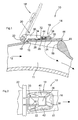
- In the Fign. 1 and 2 is a section of a variable intake manifold 10 of a plurality Switch intake manifold comprehensive air intake duct system for a multi-cylinder internal combustion engine shown.
- About the shift intake 10th combustion air is supplied to a cylinder of the internal combustion engine, and admittedly via a long intake path 12 or via a short intake path 14.
- the shift intake 10 has for this purpose at its cylinder-side portion a Short-circuit opening 16, which is closed by a switching flap 18.
- the Switching flap 18 is attached to a flap lever 20 fixed to a rotatable lever shaft 22 is attached.
- the switching flap 18 At low speeds of the internal combustion engine, the switching flap 18 is in their Closed position and closes the short-circuit opening 16. The sucked air passes exclusively through the long intake 12 in the cylinder Internal combustion engine. At higher speeds, the switching flap 18 is in their Open position pivoted 18 '. This is done by a corresponding Shaft drive, through which the lever shaft 22 can be rotated by about 40 °, whereby the switching flap 18 is pivoted in its open position. In the Open position of the switching flap 18 ', the intake air on the short Intake path 14 get into the intake manifold. At low speeds, the Lever shaft 22 turned back by their drive and the switching flap 18th pivoted into its closed position.
- the switching flap 18 is formed by a plate body 24, the center and on the channel outside a dome 26 has.
- the calotte 26 takes one Solid angle of about 30 °, has a radius of about 15 mm and protrudes about 1.0 mm from the back surface 28 of the switching flap 18th out.
- the flap lever 28 is spaced from two parallel to each other Lever leaves 30 and one of the two lever blades 30 in a transverse plane held plate 32 formed.
- the plate 32 projects radially outward over the radial ends of the two lever blades 30 addition.
- the protruding part of the completely flat and plan plate 32 is plugged into a pocket 34, that of a lug cover 36 with corresponding pocket side walls 38,40,42 is formed.
- the Stecktaschendeckel 36 and the Socket sidewalls are welded to the valve body 24.
- a rubber-elastic elastomeric ring 44 attached, through which the plate 32 on the Dome 26 is pressed and also the plate 32 in the pocket 34 fixed is stuck.
- the plate body 24 has a circumferential rubber-elastic sealing lip 46th on, with the switching flap 18 closed on the circumferential closing seat 48th the short-circuit opening 16 is pressed.
- the dome height and the pocket dimensions are chosen so that a Swing angle of the switching flap 18 relative to the lever plate 32 of about 1.0 ° results in or a pivoting movement of about 0.5 mm at each corner of the Allow switching flap 18.
Landscapes
- Engineering & Computer Science (AREA)
- Chemical & Material Sciences (AREA)
- Combustion & Propulsion (AREA)
- Mechanical Engineering (AREA)
- General Engineering & Computer Science (AREA)
- Characterised By The Charging Evacuation (AREA)
Abstract
Description
- Fig. 1
- einen Abschnitt eines Schaltsaugrohres mit einer Kurzschlußöffnung und einer Schaltklappe im Längsschnitt und
- Fig. 2
- den Schaltsaugrohr-Abschnitt und die Schaltklappe der Fig. 1 in Draufsicht.
Claims (7)
- Schaltsaugrohr für Brennkraftmaschinen, mit
einem Ansaugkanal (11) mit einer Kurzschlußöffnung (16),
einer Schaltklappe (18) zum Verschließen und Öffnen der Kurzschlußöffnung (16) und
einem angetriebenen und mit der Schaltklappe (18) durch eine nicht starre Verbindung verbundenen Klappenhebel (20) zur Betätigung der Schaltklappe (18),
dadurch gekennzeichnet, dass die Verbindung von einer Platte (32) einerseits und einer Kalotte (26) andererseits gebildet wird. - Schaltsaugrohr nach Anspruch 1, dadurch gekennzeichnet, dass die Schaltklappe (18) die Kalotte (26) und der Klappenhebel (20) die Platte (32) aufweist.
- Schaltsaugrohr nach Anspruch 2, dadurch gekennzeichnet, dass die Kalotte (26) einstückig mit der Schaltklappe (18) ausgebildet ist.
- Schaltsaugrohr nach Anspruch 2 oder 3, dadurch gekennzeichnet, dass die Kalotte (26) ungefähr in der Mitte der Schaltklappe (18) angeordnet ist.
- Schaltsaugrohr nach einem der Ansprüche 1-4, dadurch gekennzeichnet, dass die Kalottenhöhe derart gewählt ist, dass der Schaltklappen-Kippwinkel mindestens 1,0° in jede Richtung beträgt.
- Schaltsaugrohr nach einem der Ansprüche 2-5, dadurch gekennzeichnet, dass die Schaltklappe (18) eine die Kalotte (26) beinhaltende Stecktasche (34) aufweist, in die die Klappenhebel-Platte (32) eingesteckt ist.
- Schaltsaugrohr nach Anspruch 6, dadurch gekennzeichnet, dass zwischen der Plattenrückseite und einer Stecktaschenwand (36) ein elastisches Spannelement (44) angeordnet ist, das die Platte (32) auf die Kalotte (26) drückt.
Applications Claiming Priority (2)
| Application Number | Priority Date | Filing Date | Title |
|---|---|---|---|
| DE10148601A DE10148601B4 (de) | 2001-10-02 | 2001-10-02 | Schaltsaugrohr |
| DE10148601 | 2001-10-02 |
Publications (2)
| Publication Number | Publication Date |
|---|---|
| EP1300557A2 true EP1300557A2 (de) | 2003-04-09 |
| EP1300557A3 EP1300557A3 (de) | 2004-08-18 |
Family
ID=7701124
Family Applications (1)
| Application Number | Title | Priority Date | Filing Date |
|---|---|---|---|
| EP02022012A Withdrawn EP1300557A3 (de) | 2001-10-02 | 2002-10-01 | Schaltsaugrohr |
Country Status (3)
| Country | Link |
|---|---|
| US (1) | US6688271B2 (de) |
| EP (1) | EP1300557A3 (de) |
| DE (1) | DE10148601B4 (de) |
Citations (1)
| Publication number | Priority date | Publication date | Assignee | Title |
|---|---|---|---|---|
| DE19714311A1 (de) | 1997-04-08 | 1998-10-15 | Pierburg Ag | Luftansaugkanalsystem für Brennkraftmaschinen |
Family Cites Families (5)
| Publication number | Priority date | Publication date | Assignee | Title |
|---|---|---|---|---|
| DE19526241B4 (de) * | 1995-07-18 | 2006-02-09 | Pierburg Gmbh | Lufteinlaßkanalsystem für Brennkraftmaschinen |
| FR2746446B1 (fr) * | 1996-03-19 | 1998-05-22 | Magneti Marelli France | Collecteur d'admission d'air, a element escamotable a conduit acoustique, pour moteurs a combustion interne |
| FR2751394B1 (fr) * | 1996-07-18 | 1999-02-05 | Eaton Sa Monaco | Electrovanne pour distribution de liquide |
| DE19845879B4 (de) * | 1998-10-06 | 2007-02-22 | Pierburg Gmbh | Luftansaugkanalsystem für Brennkraftmaschinen |
| DE10018627C1 (de) * | 2000-04-14 | 2002-06-13 | Saxonia Umformtechnik Gmbh | Drosselklappe |
-
2001
- 2001-10-02 DE DE10148601A patent/DE10148601B4/de not_active Expired - Fee Related
-
2002
- 2002-09-27 US US10/259,092 patent/US6688271B2/en not_active Expired - Fee Related
- 2002-10-01 EP EP02022012A patent/EP1300557A3/de not_active Withdrawn
Patent Citations (1)
| Publication number | Priority date | Publication date | Assignee | Title |
|---|---|---|---|---|
| DE19714311A1 (de) | 1997-04-08 | 1998-10-15 | Pierburg Ag | Luftansaugkanalsystem für Brennkraftmaschinen |
Also Published As
| Publication number | Publication date |
|---|---|
| DE10148601B4 (de) | 2007-01-25 |
| DE10148601A1 (de) | 2003-04-24 |
| EP1300557A3 (de) | 2004-08-18 |
| US6688271B2 (en) | 2004-02-10 |
| US20030062014A1 (en) | 2003-04-03 |
Similar Documents
| Publication | Publication Date | Title |
|---|---|---|
| EP1026407B1 (de) | Fluidisches Steuerelement | |
| DE60022278T2 (de) | Einlasssteuersystem für Brennkraftmaschine | |
| DE19504382A1 (de) | Ansaugsystem | |
| EP0725210B1 (de) | Saugmodul | |
| WO2015010890A2 (de) | Ventil | |
| EP0110077A2 (de) | Drosselklappenstutzen | |
| DE69700746T2 (de) | Einlasskrümmer mit schwenkbarem, mit einem akustischen kanal versehenen element für brennkraftmaschinen | |
| EP0759521B1 (de) | Rückschlagventil | |
| DE29819856U1 (de) | Steuerglied eines Piezoventils | |
| DE60030774T2 (de) | Reversierbar-zweikammer-druckluftmotor | |
| DE102012203156A1 (de) | Mischventil einer Brennkraftmaschine | |
| DE10148601B4 (de) | Schaltsaugrohr | |
| DE102010045540A1 (de) | Schwenkwinkelsensor | |
| DE3633259A1 (de) | Drehventileinrichtung fuer brennkraftmaschinen | |
| EP0733790A2 (de) | Verstelleinrichtung | |
| DE10018627C1 (de) | Drosselklappe | |
| EP1520996B1 (de) | Fluidbetätigter Drehantrieb | |
| DE10143384C1 (de) | Schaltklappeneinrichtung | |
| DE102016123676B4 (de) | Ladungsbewegungsklappendichtung und Montageverfahren | |
| DE69100260T2 (de) | Ventilanordnung. | |
| DE102009015976B4 (de) | Ventil mit drehbarem Ventilglied | |
| DE4028489A1 (de) | Luftangsaugeinrichtung fuer eine brennkraftmaschine | |
| EP0726178B1 (de) | Luftfederventil mit Feineinstellung | |
| EP1792095B1 (de) | Kupplung zur drehmomentübertragung | |
| DE69412417T2 (de) | Drosselmechanismus |
Legal Events
| Date | Code | Title | Description |
|---|---|---|---|
| PUAI | Public reference made under article 153(3) epc to a published international application that has entered the european phase |
Free format text: ORIGINAL CODE: 0009012 |
|
| AK | Designated contracting states |
Kind code of ref document: A2 Designated state(s): AT BE BG CH CY CZ DE DK EE ES FI FR GB GR IE IT LI LU MC NL PT SE SK TR Designated state(s): AT BE BG CH CY CZ DE DK EE ES FI FR GB GR IE IT LI LU MC NL PT SE SK TR |
|
| AX | Request for extension of the european patent |
Extension state: AL LT LV MK RO SI |
|
| PUAL | Search report despatched |
Free format text: ORIGINAL CODE: 0009013 |
|
| AK | Designated contracting states |
Kind code of ref document: A3 Designated state(s): AT BE BG CH CY CZ DE DK EE ES FI FR GB GR IE IT LI LU MC NL PT SE SK TR |
|
| AX | Request for extension of the european patent |
Extension state: AL LT LV MK RO SI |
|
| AKX | Designation fees paid | ||
| REG | Reference to a national code |
Ref country code: DE Ref legal event code: 8566 |
|
| DBV | Designated contracting states (deleted) | ||
| STAA | Information on the status of an ep patent application or granted ep patent |
Free format text: STATUS: THE APPLICATION IS DEEMED TO BE WITHDRAWN |
|
| 18D | Application deemed to be withdrawn |
Effective date: 20050219 |