EP1300496A1 - Spin-drawing texturing apparatus - Google Patents
Spin-drawing texturing apparatus Download PDFInfo
- Publication number
- EP1300496A1 EP1300496A1 EP02019825A EP02019825A EP1300496A1 EP 1300496 A1 EP1300496 A1 EP 1300496A1 EP 02019825 A EP02019825 A EP 02019825A EP 02019825 A EP02019825 A EP 02019825A EP 1300496 A1 EP1300496 A1 EP 1300496A1
- Authority
- EP
- European Patent Office
- Prior art keywords
- winding
- spin
- threads
- module
- texturing
- Prior art date
- Legal status (The legal status is an assumption and is not a legal conclusion. Google has not performed a legal analysis and makes no representation as to the accuracy of the status listed.)
- Withdrawn
Links
Images


Classifications
-
- D—TEXTILES; PAPER
- D01—NATURAL OR MAN-MADE THREADS OR FIBRES; SPINNING
- D01D—MECHANICAL METHODS OR APPARATUS IN THE MANUFACTURE OF ARTIFICIAL FILAMENTS, THREADS, FIBRES, BRISTLES OR RIBBONS
- D01D13/00—Complete machines for producing artificial threads
- D01D13/02—Elements of machines in combination
-
- D—TEXTILES; PAPER
- D01—NATURAL OR MAN-MADE THREADS OR FIBRES; SPINNING
- D01D—MECHANICAL METHODS OR APPARATUS IN THE MANUFACTURE OF ARTIFICIAL FILAMENTS, THREADS, FIBRES, BRISTLES OR RIBBONS
- D01D13/00—Complete machines for producing artificial threads
-
- D—TEXTILES; PAPER
- D02—YARNS; MECHANICAL FINISHING OF YARNS OR ROPES; WARPING OR BEAMING
- D02G—CRIMPING OR CURLING FIBRES, FILAMENTS, THREADS, OR YARNS; YARNS OR THREADS
- D02G1/00—Producing crimped or curled fibres, filaments, yarns, or threads, giving them latent characteristics
- D02G1/02—Producing crimped or curled fibres, filaments, yarns, or threads, giving them latent characteristics by twisting, fixing the twist and backtwisting, i.e. by imparting false twist
- D02G1/0206—Producing crimped or curled fibres, filaments, yarns, or threads, giving them latent characteristics by twisting, fixing the twist and backtwisting, i.e. by imparting false twist by false-twisting
- D02G1/0266—Producing crimped or curled fibres, filaments, yarns, or threads, giving them latent characteristics by twisting, fixing the twist and backtwisting, i.e. by imparting false twist by false-twisting false-twisting machines
-
- D—TEXTILES; PAPER
- D02—YARNS; MECHANICAL FINISHING OF YARNS OR ROPES; WARPING OR BEAMING
- D02G—CRIMPING OR CURLING FIBRES, FILAMENTS, THREADS, OR YARNS; YARNS OR THREADS
- D02G1/00—Producing crimped or curled fibres, filaments, yarns, or threads, giving them latent characteristics
- D02G1/12—Producing crimped or curled fibres, filaments, yarns, or threads, giving them latent characteristics using stuffer boxes
-
- D—TEXTILES; PAPER
- D02—YARNS; MECHANICAL FINISHING OF YARNS OR ROPES; WARPING OR BEAMING
- D02G—CRIMPING OR CURLING FIBRES, FILAMENTS, THREADS, OR YARNS; YARNS OR THREADS
- D02G1/00—Producing crimped or curled fibres, filaments, yarns, or threads, giving them latent characteristics
- D02G1/20—Combinations of two or more of the above-mentioned operations or devices; After-treatments for fixing crimp or curl
-
- Y—GENERAL TAGGING OF NEW TECHNOLOGICAL DEVELOPMENTS; GENERAL TAGGING OF CROSS-SECTIONAL TECHNOLOGIES SPANNING OVER SEVERAL SECTIONS OF THE IPC; TECHNICAL SUBJECTS COVERED BY FORMER USPC CROSS-REFERENCE ART COLLECTIONS [XRACs] AND DIGESTS
- Y10—TECHNICAL SUBJECTS COVERED BY FORMER USPC
- Y10S—TECHNICAL SUBJECTS COVERED BY FORMER USPC CROSS-REFERENCE ART COLLECTIONS [XRACs] AND DIGESTS
- Y10S425/00—Plastic article or earthenware shaping or treating: apparatus
- Y10S425/017—Filament stretching apparatus
-
- Y—GENERAL TAGGING OF NEW TECHNOLOGICAL DEVELOPMENTS; GENERAL TAGGING OF CROSS-SECTIONAL TECHNOLOGIES SPANNING OVER SEVERAL SECTIONS OF THE IPC; TECHNICAL SUBJECTS COVERED BY FORMER USPC CROSS-REFERENCE ART COLLECTIONS [XRACs] AND DIGESTS
- Y10—TECHNICAL SUBJECTS COVERED BY FORMER USPC
- Y10S—TECHNICAL SUBJECTS COVERED BY FORMER USPC CROSS-REFERENCE ART COLLECTIONS [XRACs] AND DIGESTS
- Y10S425/00—Plastic article or earthenware shaping or treating: apparatus
- Y10S425/115—Lubricator
Definitions
- the invention relates to a spin-stretch texturing machine for the production of crimped Threads according to the preamble of claim 1.
- spin-stretch texturing machines for the production of crimped threads are generally known and are used mainly for the production of carpet yarns used.
- the spin-stretch texturing machine has one Spinning device, a stretching device, a texturing device and a Take-up device. In doing so, several threads running in parallel are made spun in a polymer melt, stretched together and side by side in parallel textured. The threads crimped after texturing will end wound up next to each other in parallel by the winding device.
- the spinning device, the stretching device, the texturing device and the Winding device arranged vertically one below the other.
- Such machines have the disadvantage that the threads can be laid over several floors must be performed.
- a spin-stretch texturing machine is known from EP 0 718 424 A1 which the disadvantage of the bad threading possibility was eliminated, that the stretching device, the texturing device and the winding device were each combined into a machine unit to create a thread texture and wrap.
- Several machine units are next to each other arranged.
- this design of the stretch texturing machine has generally the disadvantage that corresponding to the parallel processing of several threads many machine units are required.
- the integration the functional modules to a machine unit disadvantageous because of mutual Influences are inevitable, for example, when changing the bobbin.
- Another object of the invention is to treat and wind up to train the threads as flexibly as possible.
- the task is accomplished by a spin-draw texturing machine with the features of claim 1 solved.
- the invention is particularly characterized in that the facilities that to carry out the essential process steps for the production of crimped Threads are required, separated according to their function and to individual machine modules are summarized. So they form to treat the spun Threads required stretching device and texturing device together a treatment module.
- the treatment module is below the spinning device arranged so that the freshly spun threads immediately for treatment can enter the treatment module. After spinning and the When the threads are treated, the threads are wound into bobbins.
- the Winding device arranged on a winding module, which is immediately adjacent the treatment module is set up and thus forms a machine longitudinal side.
- the texturing machine according to the invention thus has the particular advantage a low overall height, so that the stretching device and the texturing device in the treatment module and the winding device in the winding module can be operated from one level by the operating personnel.
- the division of the functional groups according to the invention is a further advantage given that the bobbin changing operations in the winding device without significant influence on those arranged in the adjacent treatment module Facilities can be done.
- the particularly advantageous development of the invention according to claim 2 is characterized by the fact that the narrow thread spacing to each other from the Treatment module emerging threads wound without significant spread can be.
- the stretching device, the texturing device and the winding device essentially form a common management level for treatment and winding the threads. This can cause thread tension differences avoided in the individual threads due to larger spreads advantageous become.
- a particularly flexible design of the spin-stretch texturing machine is due to the Further development of the invention according to claim 3.
- the floor level superposed winding units of the winding device independently driven and controlled. Every curled thread leaves individually wind up into a bobbin, taking up the winding speeds are the same.
- a particular advantage of this training is that Thread break in a winding unit no process interruption is required and thus a high utilization of the machine is guaranteed.
- the winding units can each have a drivable winding spindle Have recording of the coil. For a continuous winding of the threads to ensure, the winding units could each have two drivable winding spindles for alternately holding the coil.
- the winding device is assigned a suction device, which Suction device for each winding unit one upstream suction nozzle having. This is a continuous withdrawal of the threads from the treatment module guaranteed even if the thread breaks in one of the winding units.
- the particularly advantageous developments of the invention according to claim 8 and 9 are characterized by a very high degree of automation. It is a robot for thread guidance when threading at the beginning of the process and a doffer is provided for changing the bobbins in the winding units.
- the robot or the doffer is preferably movable on the longitudinal side of the machine guided so that a thread guide from the spinning device to the winding device is possible.
- the embodiment variant of the invention is characterized by high operational reliability. Likewise, volatile constituents are removed during of the company, such as, for example, relationship fog, is advantageously shielded.
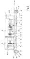
- FIG. 1 and 2 show a first exemplary embodiment of the invention Spin-stretch texturing machine shown.
- Fig. 1 is a schematic front view and in Fig. 2 schematically a top view of the spin-draw texturing machine shown.
- Fig. 1 is a schematic front view and in Fig. 2 schematically a top view of the spin-draw texturing machine shown.
- the spin-stretch texturing machine has a spinning device 1 which is based on supports a treatment module 6.
- the spinning device comprises a melt feed 2, a spinning beam 3, several on the underside of the spinning beam 3 arranged spinnerets 4 and a spinning shaft 5.
- the treatment module 6 is designed as a machine frame part to a Stretching device 11 and a texturing device 14 to wear.
- a winding module 10 is set up.
- the winding module 10 is also designed as a frame part for receiving a winding device 15 and forms a machine longitudinal side 38 with the treatment module 6.
- the preparation device 9 several thread guides 8 are assigned to form the threads 7. Furthermore is the preparation device 9 advantageously with a suction and a cutting device (not shown here) coupled.
- the stretching device 11 is through two godet units 13.1 and 13.2 are formed.
- the godet unit 13.1 for example formed by two powered godets.
- the godet unit 13.2 is exemplified as a driven godet and an overflow roller that are wrapped around the thread several times.
- That of the stretching device 11 downstream texturing device 14 consists of a texturing nozzle 39 and a plurality of discharge pipes 40.
- the texturing nozzle 39 contains a plurality of guide channels and stuffer boxes, in each of which a thread 7 forms a thread plug 35 is compressed (not shown here).
- a deflection roller 12.2 is arranged between the texturing device 14 and the delivery mechanism 16.
- the winding device 15 contained in the winding module 2 consists of several Winding units 17.1 to 17.3, which are arranged one above the other in tiers are.
- Each of the winding units 17.1 to 17.3 each have a spindle carrier 18 on which two projecting winding spindles 37.1 and 37.2 are arranged are.
- the spindle carrier 18 is rotatably mounted so that the winding spindles 37.1 and 37.2 alternately pivoted into a winding area and a changing area can be.
- a coil 41 is placed on the winding spindle 37 wound.
- the winding unit 17 has a dancer arm control 21, a traversing unit 20 and a contact roller 19.
- the drive of the winding spindle 37 is controlled so that a constant Winding speed is maintained.
- the winding spindle 37 can do this directly by a spindle drive or indirectly by a driven contact roller 19 are driven.
- the threads 7 are over a deflection roller 12.3 and several Thread guide 46 in the winding module 10 to the winding units 17.1 to 17.3 guided.
- the thread guides 46 can also be designed as a deflection roller.
- the spin-stretch texturing machine is a polymer melt in the spinning device, for example by means of an extruder fed to the spinning device 1 and via the melt feed 2 Abandoned spinning beam 3.
- the spinnerets 4 Through the spinnerets 4, the polymer melt in extruded three bundles of filaments emerging side by side. Each of the Filament bundles are brought together to a thread 7 by the thread guides 8.
- the threads 7 are removed from the spinning device by the stretching device 11 1 subtracted.
- the threads 7 are in the preparation device 9 prepared and then via the guide roller 12.1 to the stretching device 11 guided.
- the parallel threads 7 are in their thread running plane Rotated 90 °. In the stretching device 11, the threads 7 are stretched between the godet units 13.1 and 13.2.
- the godet units 13.1 and 13.2 are driven at a differential speed.
- the stretching can be the godet units 13.1 and / or the godet unit 13.2 be heatable.
- the threads 7 become parallel drawn into the texturing device 14.
- Each thread 7 is closed a thread plug 35 is stowed in the texturing nozzle 39.
- the thread plugs 35 become the now crimped threads 7 dissolved and led to the winding device 15 via the delivery mechanism 16.
- the delivery unit 16 is exemplified here as a godet unit that is multiple is wound around the threads 7, executed.
- the threads 7 are on the individual winding units 17.1, 17.2 and 17.3 divided and each floor to a coil 41 wound.
- the winding units 17 can be operated together via group drives or be designed to be driven independently by individual drives.
- a regulation in this case, for example, a dancer arm regulation 21, ensures that each of the threads 7 with the same winding speed is wound up.
- a doffer 26 for executing the Assigned spool change.
- the doffer 26 is for this purpose in a guide rail 27 guided parallel to the machine longitudinal side 38 in the area of the winding module 10.
- the doffer 26 has a carrier 28 which is in the guide rail 27 Floor is guided.
- a holder 29 is formed, which for Execution of the bobbin change required gripping arms.
- the doffer is able to complete all movements such as attaching the empty pods, taking off full bobbins and, if necessary, threading in the take-up unit.
- the embodiment demonstrates how to thread the threads 7 at the start of the process 1 and 2 a robot 22, which is parallel to the machine longitudinal side 38 in a Guide rail 23 is guided.
- the guide rail 23 is above the treatment module 6 and the winding module 10.
- a carrier 24 is guided, on which a holder 25 is designed to be movable is.
- the holder 25 contains all the necessary gripping arms and drives to To be able to apply the threads.
- the treatment devices 9, 11, 14 are on the treatment module during operation 6 and the winding device 15 on the winder module 10 shielded on the outside.
- the treatment module 6 a carrier 42 with the side walls 43.1 and 43.2. Are on the carrier 42 the treatment devices 9, 11 and 14 are arranged.
- Protective cladding 36.1 is an encapsulation formed by which the treatment facilities 9, 11 and 14 shielded from the outside towards the machine longitudinal side 38 are.
- the winding module 10 is through a carrier 44 and the side walls 45.1 and 45.2 are formed.
- the side walls 45.1 and 45.2 are on the for Carrier 44 opposite side by a protective cover 36.2 with each other connected, which is movable parallel to the machine longitudinal side 38.
- the protective covering 36.2 forms with the side walls 45.1 and 45.2 an encapsulation.
- the protective cover 36.1 and 36.2 is in each case formed by a closed, for example transparent wall, which with an upper cover (not shown here) for a complete encapsulation leads, for example, to reduce the amount of dust and noise as well as the operating personnel to protect against rotating components or, for example, at to be able to air-condition sensitive materials.
- FIG. 3 shows a further exemplary embodiment of the spin-stretch texturing machine according to the invention shown schematically in a front view.
- the Components with the same functions have been given identical reference symbols.
- the Structure of the embodiment is essentially identical to the previous one Embodiment. In this respect, only the differences are shown below explained and otherwise reference to the preceding description of the figures 1 and 2 taken.
- the treatment module 6 and the winding module are below the spinning device 1 10 set up side by side on a machine longitudinal side.
- the treatment module 6 contains a preparation device arranged one after the other in the thread running direction 9, a deflection roller 12.1, a delivery unit 30, a stretching device 11, a texturing device 14, a cooling device 31, two delivery units 16.1 and 16.2 and a swirling device 32, which is between the delivery plants 16.1 and 16.2 is arranged.
- the threads 7 by an additional Delivery unit 30 withdrawn from the spinning device 1 and to the following Stretching device 11 out.
- the stretching device is made up of two godet units 13.1 and 13.2 formed, each containing two driven godets.
- the threads 4 are parallel to each other with several wraps led around the respective godet units 13.1 and 13.2.
- the godet units 13.1 and 13.2 driven at differential speed, so that the Threads are drawn.
- a compression crimp occurs within the texturing device 14.
- the texturing device 14 a texturing nozzle 39.
- the texturing nozzle 39 is a cooling device 31 subordinate to the circumference side by side per thread a circumferential groove to the thread plugs 35 emerging from the texturing device 14 take.
- the cooling device 31 is designed as a drum on its circumference the thread plugs 35 are cooled. To loosen the thread plugs 35 are the threads 7 by the downstream delivery unit 16.1 of the cooling device 31 deducted.
- the winding units 17 have here each have a spindle carrier 18 with a winding spindle 37 on the circumference of a driven contact roller 19 are held.
- the spindle carrier 18 are pivoted.
- Traversing device 20 is provided, which preferably by a thread guide 46 an overflow thread running out takes over and essentially parallel leads to the coil 41 back and forth.
- the winding device 15 is assigned a suction device 33, which has several Has suction port 34.
- each winding unit 17.1 to 17.3 is one assigned to the suction port 34.
- the suction device 33 is with a yarn container (not shown here) connected. In the event of a bobbin change or in the event that a thread break occurs in one of the winding units 17.1 to 17.3, becomes the incoming thread over the respectively assigned suction port 34 the suction device 33 and fed to a yarn container. Thereby it is ensured that the treatment facilities in the treatment module 6 can continue to be operated without interference. Switching off the Process is not required.
- Fig. 3 In the spin-draw texturing machine shown in Fig. 3 is on the side of the winding module 10, an operating aisle is formed in which the doffer 26 is guided is.
- the doffer 26 is identical to the previous embodiment and takes over the bobbin change in the winding units 17.1 until March 17th
- the robot 22 For placing the threads 7 in the treatment devices of the treatment module 6, the robot 22 is movably guided parallel to the longitudinal side of the machine.
- the Robot 22 is identical to the previous embodiment, so that reference is made to the previous description.
- FIG. 1 to 3 are in structure and Arrangement of the treatment devices and the winding device as an example.
- Through the lateral arrangement of the winding device in the winding module results a very compact arrangement with a height that can be less than 2 m. This makes the treatment facilities simple and easy to use as well as the rewinder.
- Individual treatment devices can also be removed from the treatment module removed or replaced, for example uncrimped FDY yarns or to produce POY yarns.
- the number is and the execution of the godets is basically freely selectable.
- the design the stretching device depends on the manufacturing process and the whole type.
- the number of threads which are guided and treated in parallel is also shown three threads) exemplary. So single threads or multiple threads can be without Managing, handling and winding up problems.
- the winding units are also formed, for example, by two winding stations, which can be used alternately to wind up the thread.
- Thread guidance in the winding area results on each winding unit same run conditions. It is therefore a gentle and even winding the threads guaranteed.
- the winding units can be dependent on the number of threads both vertically one above the other and horizontally arrange next to each other.
- Robots and doffers can be used advantageously for automation.
- a robot for threading only for Treatment facilities of the treatment module 6 to be responsible.
- Such one Robot is able to perform all necessary movements and mooring processes perform.
- the treatment facilities of the treatment module could do this such as the preparation device, the texturing device and the swirling device corresponding auxiliary devices exhibit.
- a second robot could thread the threads in the take-up reel and change the bobbin.
Abstract
Description
Die Erfindung betrifft eine Spinn-Streck-Texturiermaschine zur Herstellung gekräuselter
Fäden gemäß dem Oberbegriff des Anspruchs 1.The invention relates to a spin-stretch texturing machine for the production of crimped
Threads according to the preamble of
Derartige Spinn-Streck-Texturiermaschinen zur Herstellung gekräuselter Fäden sind allgemein bekannt und werden im wesentlichen zur Herstellung von Teppichgarnen eingesetzt. Hierzu weist die Spinn-Streck-Texturiermaschine eine Spinneinrichtung, eine Streckeinrichtung, eine Texturiereinrichtung und eine Aufwickeleinrichtung auf. Dabei werden mehrere parallel laufende Fäden aus einer Polymerschmelze gesponnen, gemeinsam verstreckt und parallel nebeneinander texturiert. Die nach der Texturierung gekräuselten Fäden werden am Ende durch die Aufwickeleinrichtung parallel nebeneinander aufgewickelt. Hierzu sind die Spinneinrichtung, die Streckeinrichtung, die Texturiereinrichtung und die Aufwickeleinrichtung vertikal untereinander angeordnet. Derartige Maschinen besitzen jedoch den Nachteil, daß die Fäden zum Anlegen über mehrere Etagen geführt werden müssen.Such spin-stretch texturing machines for the production of crimped threads are generally known and are used mainly for the production of carpet yarns used. For this purpose, the spin-stretch texturing machine has one Spinning device, a stretching device, a texturing device and a Take-up device. In doing so, several threads running in parallel are made spun in a polymer melt, stretched together and side by side in parallel textured. The threads crimped after texturing will end wound up next to each other in parallel by the winding device. For this are the spinning device, the stretching device, the texturing device and the Winding device arranged vertically one below the other. Such machines However, they have the disadvantage that the threads can be laid over several floors must be performed.
Aus der EP 0 718 424 A1 ist eine Spinn-Streck-Texturiermaschine bekannt, bei welcher der Nachteil der schlechten Einfädelmöglichkeit dadurch behoben wurde, daß die Streckeinrichtung, die Texturiereinrichtung und die Aufwickeleinrichtung jeweils zu einer Maschineneinheit zusammengefaßt wurden, um einen Faden zu texturieren und aufzuwickeln. Dabei sind mehrere Maschineneinheiten nebeneinander angeordnet. Diese Ausbildung der Streck-Texturiermaschine besitzt jedoch generell den Nachteil, daß zur parallelen Bearbeitung mehrerer Fäden entsprechend viele Maschineneinheiten erforderlich sind. Desweiteren ist die Integration der Funktionsbaugruppen zu einer Maschineneinheit nachteilig, da gegenseitige Beeinflussungen beispielsweise bei einem Spulenwechsel unumgänglich sind. A spin-stretch texturing machine is known from EP 0 718 424 A1 which the disadvantage of the bad threading possibility was eliminated, that the stretching device, the texturing device and the winding device were each combined into a machine unit to create a thread texture and wrap. Several machine units are next to each other arranged. However, this design of the stretch texturing machine has generally the disadvantage that corresponding to the parallel processing of several threads many machine units are required. Furthermore, the integration the functional modules to a machine unit disadvantageous because of mutual Influences are inevitable, for example, when changing the bobbin.
Es ist somit Aufgabe der Erfindung, eine Spinn-Streck-Texturiermaschine zur Herstellung gekräuselter Fäden bereitzustellen, welche einen bedienungsfreundlichen kompakten Aufbau aufweist.It is therefore an object of the invention to provide a spin-draw texturing machine To provide manufacture of crimped threads which is easy to use has a compact structure.
Ein weiteres Ziel der Erfindung liegt darin, die Behandlung sowie das Aufwickeln der Fäden möglichst flexibel auszubilden.Another object of the invention is to treat and wind up to train the threads as flexibly as possible.
Die Aufgabe wird durch eine Spinn-Streck-Texturiermaschine mit den Merkmalen
des Anspruchs 1 gelöst.The task is accomplished by a spin-draw texturing machine with the features
of
Die Erfindung zeichnet sich besonders dadurch aus, daß die Einrichtungen, die zur Ausführung der wesentlichen Verfahrensschritte zur Herstellung gekräuselter Fäden erforderlich sind, nach ihrer Funktion getrennt und zu einzelnen Maschinenmodulen zusammengefaßt sind. So bilden die zur Behandlung der gesponnenen Fäden erforderliche Streckeinrichtung und Texturiereinrichtung gemeinsam ein Behandlungsmodul. Das Behandlungsmodul ist unterhalb der Spinneinrichtung angeordnet, so daß die frisch gesponnenen Fäden unmittelbar zur Behandlung in das Behandlungsmodul einlaufen können. Nach dem Spinnen und dem Behandeln der Fäden erfolgt die Aufwicklung der Fäden zu Spulen. Hierzu ist die Aufwickeleinrichtung an einem Wickelmodul angeordnet, das unmittelbar neben dem Behandlungsmodul aufgestellt ist und somit eine Maschinenlängsseite bildet. Die erfindungsgemäße Texturiermaschine besitzt somit den besonderen Vorteil einer geringen Bauhöhe, so daß die Streckeinrichtung und die Texturiereinrichtung in dem Behandlungsmodul sowie die Aufwickeleinrichtung in dem Wickelmodul aus einer Ebene heraus durch das Bedienpersonal bedienbar sind. Durch die erfindungsgemäße Aufteilung der Funktionsgruppen ist ein weiterer Vorteil dadurch gegeben, daß die Spulwechselvorgänge in der Aufwickeleinrichtung ohne wesentliche Beeinflussung der in dem nebenstehenden Behandlungsmodul angeordneten Einrichtungen erfolgen kann. The invention is particularly characterized in that the facilities that to carry out the essential process steps for the production of crimped Threads are required, separated according to their function and to individual machine modules are summarized. So they form to treat the spun Threads required stretching device and texturing device together a treatment module. The treatment module is below the spinning device arranged so that the freshly spun threads immediately for treatment can enter the treatment module. After spinning and the When the threads are treated, the threads are wound into bobbins. For this is the Winding device arranged on a winding module, which is immediately adjacent the treatment module is set up and thus forms a machine longitudinal side. The texturing machine according to the invention thus has the particular advantage a low overall height, so that the stretching device and the texturing device in the treatment module and the winding device in the winding module can be operated from one level by the operating personnel. By the division of the functional groups according to the invention is a further advantage given that the bobbin changing operations in the winding device without significant influence on those arranged in the adjacent treatment module Facilities can be done.
Die besonders vorteilhafte Weiterbildung der Erfindung gemäß Anspruch 2
zeichnet sich dadurch aus, daß die mit engem Fadenabstand zueinander aus dem
Behandlungsmodul austretenden Fäden ohne wesentliche Spreizung aufgewickelt
werden können. Die Streckeinrichtung, die Texturiereinrichtung und die Aufwickeleinrichtung
bilden im wesentlichen eine gemeinsame Führungsebene zur Behandlung
und Aufwicklung der Fäden. Dadurch können Fadenspannungsdifferenzen
in den einzelnen Fäden aufgrund größerer Spreizungen vorteilhaft vermieden
werden.The particularly advantageous development of the invention according to
Ein besonders flexibler Aufbau der Spinn-Streck-Texturiermaschine ist durch die Weiterbildung der Erfindung nach Anspruch 3 gegeben. Hierzu werden die etagenmäßig übereinander angeordneten Aufspuleinheiten der Aufwickeleinrichtung unabhängig voneinander angetrieben und gesteuert. Jeder gekräuselte Faden läßt sich individuell zu einer Spule aufwickeln, wobei die Aufwickelgeschwindigkeiten gleich sind. Ein besonderer Vorteil dieser Weiterbildung liegt darin, daß bei Fadenbruch in einer Aufspuleinheit keine Prozeßunterbrechung erforderlich wird und somit eine hohe Auslastung der Maschine gewährleistet ist.A particularly flexible design of the spin-stretch texturing machine is due to the Further development of the invention according to claim 3. For this, the floor level superposed winding units of the winding device independently driven and controlled. Every curled thread leaves individually wind up into a bobbin, taking up the winding speeds are the same. A particular advantage of this training is that Thread break in a winding unit no process interruption is required and thus a high utilization of the machine is guaranteed.
Die Aufspuleinheiten können hierbei jeweils eine antreibbare Spulspindel zur Aufnahme der Spule aufweisen. Um eine kontinuierliche Aufwicklung der Fäden zu gewährleisten, könnten die Aufspuleinheiten jeweils zwei antreibbare Spulspindeln zur abwechselnden Aufnahme der Spule aufweisen.The winding units can each have a drivable winding spindle Have recording of the coil. For a continuous winding of the threads to ensure, the winding units could each have two drivable winding spindles for alternately holding the coil.
Bei der Herstellung von gekräuselten Fäden werden nach dem Spinnen der Fäden
in Abhängigkeit vom Garntyp zusätzliche Behandlungen erforderlich. So wird
beispielsweise bei Verwendung von Stauchkammer-Texturiereinrichtungen eine
zusätzliche Kühleinrichtung zur Abkühlung des Fadenstopfens verwendet. Ebenso
könnte eine Verwirbelung der Fäden vor oder nach der Texturierung zur Verbesserung
eines Fadenschlusses erforderlich sein. Durch die besonders vorteilhafte
Weiterbildung der Erfindung nach Anspruch 6 ist die Möglichkeit gegeben, die
zusätzlichen Behandlungseinrichtungen in dem Behandlungsmodul zu integrieren. In the manufacture of crimped threads are made after spinning the threads
Depending on the type of yarn, additional treatments may be required. So will
for example when using stuffer box texturing devices
additional cooling device used to cool the thread plug. As well
could improve a swirling of the threads before or after texturing
a thread closure may be required. Because of the particularly advantageous
Further development of the invention according to
Um zu gewährleisten, daß bei einer Störung in der Aufwickeleinrichtung keine Prozeßunterbrechung eintritt, ist gemäß einer bevorzugten Weiterbildung der Erfindung der Aufwickeleinrichtung eine Absaugvorrichtung zugeordnet, welche Absaugvorrichtung zu jeder Aufspuleinheit jeweils einen vorgeordneten Saugstutzen aufweist. Damit wird ein kontinuierlicher Abzug der Fäden aus dem Behandlungsmodul heraus selbst bei Fadenbruch in einer der Aufspuleinheiten gewährleistet.To ensure that there is no malfunction in the take-up device Process interruption occurs is according to a preferred development of the invention the winding device is assigned a suction device, which Suction device for each winding unit one upstream suction nozzle having. This is a continuous withdrawal of the threads from the treatment module guaranteed even if the thread breaks in one of the winding units.
Die besonders vorteilhaften Weiterbildungen der Erfindung gemäß Anspruch 8
und 9 zeichnen sich durch einen sehr hohen Automatisierungsgrad aus. Dabei ist
ein Roboter zur Fadenführung beim Anlegen der Fäden zu Prozeßbeginn sowie
ein Doffer zum Wechseln der Spulen in den Aufspuleinheiten vorgesehen. Der
Roboter bzw. der Doffer ist vorzugsweise beweglich an der Maschinenlängsseite
geführt, so daß eine Fadenführung von der Spinneinrichtung bis hin zur Aufwickeleinrichtung
möglich ist.The particularly advantageous developments of the invention according to
Die Ausführungsvariante der Erfindung gemäß Anspruch 10 zeichnet sich durch eine hohe Betriebssicherheit aus. Ebenso werden flüchtige Bestandteile während des Betriebes wie beispielsweise Relationsnebel vorteilhaft abgeschirmt.The embodiment variant of the invention is characterized by high operational reliability. Likewise, volatile constituents are removed during of the company, such as, for example, relationship fog, is advantageously shielded.
Die Erfindung wird anhand einiger Ausführungsbeispiele gemäß den folgenden Figuren näher erläutert.The invention is illustrated by some embodiments according to the following Figures explained in more detail.
Es stellen dar:
- Fig. 1 und 2
- schematische Ansichten eines ersten Ausführungsbeispiels der erfindungsgemäßen Spinn-Streck-Texturiermaschine;
- Fig. 3
- schematisch eine Ansicht eines weiteren Ausführungsbeispiels der erfindungsgemäßen Spinn-Streck-Texturiermaschine.
- 1 and 2
- schematic views of a first embodiment of the spin-draw texturing machine according to the invention;
- Fig. 3
- schematically shows a view of a further embodiment of the spin-stretch texturing machine according to the invention.
In Fig. 1 und Fig. 2 ist ein erstes Ausführungsbeispiel der erfindungsgemäßen Spinn-Streck-Texturiermaschine gezeigt. In Fig. 1 ist schematisch eine Vorderansicht und in Fig. 2 schematisch eine Draufsicht der Spinn-Streck-Texturiermaschine dargestellt. Insoweit kein ausdrücklicher Bezug zu einer der Figuren gemacht ist, gilt die nachfolgende Beschreibung für beide Figuren.1 and 2 show a first exemplary embodiment of the invention Spin-stretch texturing machine shown. In Fig. 1 is a schematic front view and in Fig. 2 schematically a top view of the spin-draw texturing machine shown. Insofar as no express reference to one of the Figures is made, the following description applies to both figures.
Die Spinn-Streck-Texturiermaschine besitzt eine Spinneinrichtung 1, die sich auf
einem Behandlungsmodul 6 abstützt. Die Spinneinrichtung umfaßt eine Schmelzezuführung
2, einen Spinnbalken 3, mehrere an der Unterseite des Spinnbalkens
3 angeordnete Spinndüsen 4 sowie einen Spinnschacht 5.The spin-stretch texturing machine has a
Das Behandlungsmodul 6 ist als ein Maschinengestellteil ausgebildet, um eine
Streckeinrichtung 11 und eine Texturiereinrichtung 14 zu tragen. Neben dem Behandlungsmodul
6 ist ein Wickelmodul 10 aufgestellt. Das Wickelmodul 10 ist
ebenfalls als ein Gestellteil zur Aufnahme einer Aufwickeleinrichtung 15 ausgeführt
und bildet mit dem Behandlungsmodul 6 eine Maschinenlängsseite 38.The
In dem Behandlungsmodul 6 sind neben der Streckeinrichtung 11 und der Texturiereinrichtung
14 eine dem Auslaß der Spinneinrichtung 1 zugeordnete Präparationseinrichtung
9, eine zwischen der Präparationseinrichtung 9 und der Streckeinrichtung
11 angeordnete Umlenkrolle 12.1 sowie ein der Texturiereinrichtung
14 nachgeordnetes Lieferwerk 16 aufgenommen. Der Präparationseinrichtung 9
sind mehrere Fadenführer 8 zur Bildung der Fäden 7 zugeordnet. Desweiteren ist
die Präparationseinrichtung 9 vorteilhaft mit einer Absaugung und einer Schneideinrichtung
(hier nicht dargestellt) gekoppelt. Die Streckeinrichtung 11 wird durch
zwei Galetteneinheiten 13.1 und 13.2 gebildet. Die Galetteneinheit 13.1 wird beispielsweise
durch zwei angetriebene Galetten gebildet. Die Galetteneinheit 13.2
ist beispielhaft als eine angetriebene Galette und eine Überlaufrolle dargestellt, die
mehrfach von den Fäden umschlungen werden. Die der Streckeinrichtung 11
nachgeordnete Texturiereinrichtung 14 besteht aus einer Texturierdüse 39 und
mehreren Austragsrohren 40. Die Texturierdüse 39 enthält mehrere Führungskanäle
und Stauchkammern, in welchen jeweils ein Faden 7 zu einem Fadenstopfen
35 gestaucht wird (hier nicht dargestellt). Zwischen der Texturiereinrichtung 14
und dem Lieferwerk 16 ist eine Umlenkrolle 12.2 angeordnet.In the
Die in dem Wickelmodul 2 enthaltene Aufwickeleinrichtung 15 besteht aus mehreren
Aufspuleinheiten 17.1 bis 17.3, die etagenmäßig übereinander angeordnet
sind. Jede der Aufspuleinheiten 17.1 bis 17.3 weisen jeweils einen Spindelträger
18 auf, an welchem zwei auskragende Spulspindeln 37.1 und 37.2 angeordnet
sind. Der Spindelträger 18 ist drehbar gelagert, so daß die Spulspindeln 37.1 und
37.2 abwechselnd in einen Spulbereich und einen Wechselbereich verschwenkt
werden können. In dem Spulbereich wird auf der Spulspindel 37 eine Spule 41
gewickelt. Hierzu weist die Aufspuleinheit 17 jeweils eine Tänzerarmregelung 21,
eine Changiereinheit 20 und eine Kontaktwalze 19 auf. Durch die Tänzerarmregelung
21 wird der Antrieb der Spulspindel 37 derart geregelt, daß eine konstante
Aufwickelgeschwindigkeit eingehalten ist. Die Spulspindel 37 kann hierbei direkt
durch einen Spindelantrieb oder indirekt durch eine angetriebene Kontaktwalze 19
angetrieben werden. Die Fäden 7 werden über eine Umlenkrolle 12.3 und mehrere
Fadenführer 46 in dem Aufwickelmodul 10 zu den Aufspuleinheiten 17.1 bis 17.3
geführt. Hierbei können die Fadenführer 46 auch als Umlenkrolle ausgeführt sein.The winding
Bei dem gezeigten Ausführungsbeispiel der Spinn-Streck-Texturiermaschine wird
in der Spinneinrichtung eine Polymerschmelze beispielsweise mittels eines Extruders
der Spinneinrichtung 1 zugeführt und über die Schmelzezuführung 2 dem
Spinnbalken 3 aufgegeben. Durch die Spinndüsen 4 wird die Polymerschmelze in
jeweils drei nebeneinander austretenden Filamentbündeln extrudiert. Jedes der
Filamentbündel wird durch die Fadenführer 8 zu jeweils einem Faden 7 zusammengeführt.
Die Fäden 7 werden durch die Streckeinrichtung 11 aus der Spinneinrichtung
1 abgezogen. Dabei werden die Fäden 7 in der Präparationseinrichtung 9
präpariert und anschließend über die Umlenkrolle 12.1 zur Streckeinrichtung 11
geführt. Dabei werden die parallel geführten Fäden 7 in ihrer Fadenlaufebene um
90° gedreht. In der Streckeinrichtung 11 erfolgt ein Verstrecken der Fäden 7 zwischen
den Galetteneinheiten 13.1 und 13.2. Die Galetteneinheiten 13.1 und 13.2
werden hierzu mit einer Differenzgeschwindigkeit angetrieben. Zur Unterstützung
der Verstreckung können die Galetteneinheiten 13.1 und/oder die Galetteneinheit
13.2 beheizbar ausgebildet sein. Nach dem Verstrecken werden die Fäden 7 parallel
in die Texturiereinrichtung 14 eingezogen. Dabei wird jeder Faden 7 jeweils zu
einem Fadenstopfen 35 in der Texturierdüse 39 aufgestaut. Am Ende der Texturiereinrichtung
14 werden die Fadenstopfen 35 zu den nun gekräuselten Fäden 7
aufgelöst und über das Lieferwerk 16 zu der Aufwickeleinrichtung 15 geführt.
Das Lieferwerk 16 ist hierbei beispielhaft als eine Galetteneinheit, die mehrfach
von den Fäden 7 umschlungen ist, ausgeführt.In the embodiment shown, the spin-stretch texturing machine is
a polymer melt in the spinning device, for example by means of an extruder
fed to the
In der Aufwickeleinrichtung 15 werden die Fäden 7 auf die einzelnen Aufspuleinheiten
17.1, 17.2 und 17.3 aufgeteilt und jeder Etage zu jeweils einer Spule 41
aufgewickelt. Hierzu können die Aufspuleinheiten 17 gemeinsam über Gruppenantriebe
oder unabhängig über Einzelantriebe angetrieben ausgebildet sein. In
jedem Fall wird durch eine Regelung, in diesem Fall beispielsweise eine Tänzerarmregelung
21, gewährleistet, daß jeder der Fäden 7 mit gleicher Aufwickelgeschwindigkeit
aufgespult wird. Durch die erfindungsgemäße Trennung der Funktionsbaugruppen
ist an dem Wickelmodul 10 ein Doffer 26 zur Ausführung der
Spulwechsel zugeordnet. Der Doffer 26 wird hierzu in einer Führungsschiene 27
parallel zur Maschinenlängsseite 38 im Bereich des Wickelmoduls 10 geführt.
Der Doffer 26 weist hierzu einen Träger 28 auf, der in der Führungsschiene 27 am
Boden geführt ist. An dem Träger 28 ist ein Halter 29 ausgebildet, welcher die zur
Ausführung des Spulenwechsels erforderlichen Greifarme aufweist. Der Doffer ist
in der Lage, alle Bewegungsabläufe wie Aufstecken der leeren Hülsen, Abnahme
der vollen Spulen und ggf. auch Anlegen der Fäden in der Aufspuleinheit durchzuführen. In the winding
Zum Anlegen der Fäden 7 zu Prozeßbeginn weist das Ausführungsbeispiel nach
Fig. 1 und 2 einen Roboter 22 auf, der parallel zur Maschinenlängsseite 38 in einer
Führungsschiene 23 geführt ist. Die Führungsschiene 23 ist hierzu oberhalb
des Behandlungsmoduls 6 und des Wickelmoduls 10 angeordnet. In der Führungsschiene
23 ist ein Träger 24 geführt, an dem ein Halter 25 beweglich ausgebildet
ist. Der Halter 25 enthält alle notwendigen Greifarme und Antriebe, um das
Anlegen der Fäden ausführen zu können.The embodiment demonstrates how to thread the
Während des Betriebes sind die Behandlungseinrichtungen 9, 11, 14 am Behandlungsmodul
6 sowie die Aufwickeleinrichtung 15 an dem Wicklermodul 10 nach
außen hin abgeschirmt. Wie aus Fig. 2 ersichtlich weist das Behandlungsmodul 6
einen Träger 42 mit den Seitenwänden 43.1 und 43.2 auf. An dem Träger 42 sind
die Behandlungseinrichtungen 9, 11 und 14 angeordnet. Durch die Seitenwände
43.1 und 43.2 sowie eine parallel zur Maschinenlängsseite 38 verschiebbare
Schutzverkleidung 36.1 ist eine Kapselung gebildet, wodurch die Behandlungseinrichtungen
9, 11 und 14 nach außen hin zur Maschinenlängsseite 38 abgeschirmt
sind. Ebenso ist das Wickelmodul 10 durch einen Träger 44 und die Seitenwände
45.1 und 45.2 gebildet. Die Seitenwände 45.1 und 45.2 sind auf der zum
Träger 44 gegenüberliegenden Seite durch eine Schutzverkleidung 36.2 miteinander
verbunden, die parallel zur Maschinenlängsseite 38 beweglich ausgebildet ist.
Auch hierbei bildet die Schutzverkleidung 36.2 mit den Seitenwänden 45.1 und
45.2 eine Kapselung. Die Schutzverkleidung 36.1 und 36.2 ist hierbei jeweils
durch eine geschlossene, beispielsweise durchsichtige Wand ausgebildet, die mit
einer oberen Abdeckung (hier nicht dargestellt) zu einer vollständigen Kapselung
führt, um beispielsweise den Staubanfall und Lärm zu reduzieren sowie das Bedienpersonal
gegenüber rotierenden Bauteilen zu schützen oder beispielsweise bei
empfindlichen Materialien eine Klimatisierung vornehmen zu können.The
In Fig. 3 ist ein weiteres Ausführungsbeispiel der erfindungsgemäßen Spinn-Streck-Texturiermaschine in einer Vorderansicht schematisch dargestellt. Die Bauteile mit gleichen Funktionen haben identische Bezugszeichen erhalten. Der Aufbau des Ausführungsbeispiels ist im wesentlichen identisch zu dem vorhergehenden Ausführungsbeispiel. Insoweit werden nachfolgend nur die Unterschiede erläutert und im übrigen Bezug zu der vorhergehenden Beschreibung zu den Figuren 1 und 2 genommen.3 shows a further exemplary embodiment of the spin-stretch texturing machine according to the invention shown schematically in a front view. The Components with the same functions have been given identical reference symbols. The Structure of the embodiment is essentially identical to the previous one Embodiment. In this respect, only the differences are shown below explained and otherwise reference to the preceding description of the figures 1 and 2 taken.
Unterhalb der Spinneinrichtung 1 sind das Behandlungsmodul 6 und das Wickelmodul
10 zu einer Maschinenlängsseite nebeneinander aufgestellt. Das Behandlungsmodul
6 enthält in Fadenlaufrichtung nacheinander angeordnet eine Präparationseinrichtung
9, eine Umlenkrolle 12.1, ein Lieferwerk 30, eine Streckeinrichtung
11, eine Texturiereinrichtung 14, eine Kühleinrichtung 31, zwei Lieferwerke
16.1 und 16.2 sowie eine Verwirbelungseinrichtung 32, die zwischen den Lieferwerken
16.1 und 16.2 angeordnet ist. Gegenüber dem vorhergehenden Ausführungsbeispiel
werden bei diesem Ausführungsbeispiel die Fäden 7 durch ein zusätzliches
Lieferwerk 30 aus der Spinneinrichtung 1 abgezogen und zu der folgenden
Streckeinrichtung 11 geführt. Die Streckeinrichtung wird durch zwei Galetteneinheiten
13.1 und 13.2 gebildet, die jeweils zwei angetriebene Galetten enthalten.
Die Fäden 4 werden parallel nebeneinander mit mehreren Umschlingungen
um die jeweiligen Galetteneinheiten 13.1 und 13.2 geführt. Hierbei sind die Galetteneinheiten
13.1 und 13.2 mit Differenzgeschwindigkeit angetrieben, so daß die
Fäden verstreckt werden. Nach dem Verstrecken erfolgt eine Stauchkräuselung
innerhalb der Texturiereinrichtung 14. Hierzu weist die Texturiereinrichtung 14
eine Texturierdüse 39 auf. Der Texturierdüse 39 ist eine Kühleinrichtung 31
nachgeordnet, die am Umfang nebeneinander pro Faden eine umlaufende Nut
aufweist, um die aus der Texturiereinrichtung 14 austretenden Fadenstopfen 35 zu
übernehmen. Die Kühleinrichtung 31 ist als Trommel ausgebildet, an deren Umfang
eine Kühlung der Fadenstopfen 35 erfolgt. Zum Auflösen der Fadenstopfen
35 werden die Fäden 7 durch das nachgeordnete Lieferwerk 16.1 von der Kühleinrichtung
31 abgezogen. Zwischen den Lieferwerken 16.1 und 16.2 ist eine
Verwirbelungseinrichtung 32 an dem Behandlungsmodul 6 angeordnet. Hierbei
erfolgt eine Verwirbelung der Fäden, um einen erhöhten Fadenschluß herzustellen.
Damit ist die Behandlung der Fäden abgeschlossen. Die Fäden werden zum
Wickelmodul 10 geführt und auf die einzelnen Aufspuleinheiten 17.1, 17.2 und
17.3 der Aufwickeleinrichtung 15 verteilt. Die Aufspuleinheiten 17 weisen hierbei
jeweils einen Spindelträger 18 mit einer Spulspindel 37 auf, die am Umfang einer
angetriebenen Kontaktwalze 19 gehalten sind. Die Spindelträger 18 sind
schwenkbar ausgebildet. Im Fadenlauf vor der Kontaktwalze 19 ist jeweils eine
Changiereinrichtung 20 vorgesehen, die den von einem Fadenführer 46 vorzugsweise
eine Überlaufrolle ablaufenden Faden übernimmt und im wesentlichen parallel
zu der Spule 41 hin- und herführt.The
Der Aufwickeleinrichtung 15 ist eine Absaugvorrichtung 33 zugeordnet, die mehrere
Saugstutzen 34 aufweist. Hierbei ist jeder Aufspuleinheit 17.1 bis 17.3 einer
der Saugstutzen 34 zugeordnet. Die Absaugvorrichtung 33 ist mit einem Garnbehälter
(hier nicht dargestellt) verbunden. Für den Fall eines Spulenwechsels oder
für den Fall, daß ein Fadenbruch in einer der Aufspuleinheiten 17.1 bis 17.3 eintritt,
wird der zulaufende Faden über den jeweilig zugeordneten Saugstutzen 34
der Absaugvorrichtung 33 zugeführt und einem Garnbehälter aufgegeben. Dadurch
wird gewährleistet, daß die Behandlungseinrichtungen in dem Behandlungsmodul
6 ohne Störung weiterbetrieben werden können. Ein Abschalten des
Prozesses ist nicht erforderlich.The winding
Bei der in Fig. 3 dargestellten Spinn-Streck-Texturiermaschine ist auf der Seite
des Wickelmoduls 10 ein Bediengang gebildet, in welchem der Doffer 26 geführt
ist. Der Doffer 26 ist identisch zu dem vorhergehenden Ausführungsbeispiel ausgebildet
und übernimmt hierbei den Spulenwechsel in den Aufspuleinheiten 17.1
bis 17.3.In the spin-draw texturing machine shown in Fig. 3 is on the side
of the winding
Zum Anlegen der Fäden 7 in den Behandlungseinrichtungen des Behandlungsmoduls
6 ist der Roboter 22 beweglich parallel zur Maschinenlängsseite geführt. Der
Roboter 22 ist identisch zu dem vorhergehenden Ausführungsbeispiel ausgebildet,
so daß auf die vorhergehende Beschreibung Bezug genommen wird. For placing the
Die in den Figuren 1 bis 3 dargestellten Ausführungsbeispiele sind in Aufbau und
Anordnung der Behandlungseinrichtungen und der Aufwickeleinrichtung beispielhaft.
So können beispielsweise alle erforderlichen Bauteile im Fadeneinlaufbereich
sowie Galetten, Texturiereinheiten, Kühltrommel, Tangelung in übersichtlicher
Art und Weise in dem Behandlungsmodul 6 angeordnet sein. Durch die
seitliche Anordnung der Aufwickeleinrichtung in dem Wickelmodul ergibt sich
eine sehr kompakte Anordnung mit einer Bauhöhe, die unter 2 m liegen kann.
Damit ist eine einfache und leichte Bedienbarkeit der Behandlungseinrichtungen
sowie der Aufwickeleinrichtung gewährleistet.The embodiments shown in Figures 1 to 3 are in structure and
Arrangement of the treatment devices and the winding device as an example.
For example, all the necessary components in the thread entry area
as well as godets, texturing units, cooling drum, tangling in a clear
Be arranged in the
So können auch einzelne Behandlungseinrichtungen aus dem Behandlungsmodul entnommen oder ersetzt werden, um beispielsweise ungekräuselte FDY-Garne oder POY-Garne herzustellen.Individual treatment devices can also be removed from the treatment module removed or replaced, for example uncrimped FDY yarns or to produce POY yarns.
Bei den in den Ausführungsbeispielen gezeigten Streckeinrichtungen sind die Anzahl und die Ausführung der Galetten grundsätzlich frei wählbar. Die Ausgestaltung der Streckeinrichtung ist vom Herstellungsprozeß und vom Ganztyp abhängig.In the stretching devices shown in the exemplary embodiments, the number is and the execution of the godets is basically freely selectable. The design the stretching device depends on the manufacturing process and the whole type.
Ebenso ist die Anzahl der parallel geführten und behandelten Fäden (gezeigt sind drei Fäden) beispielhaft. So lassen sich einzelne Fäden oder mehrere Fäden ohne Probleme führen, behandeln und aufwickeln. Zum Aufwickeln der Fäden könnten die Aufspuleinheiten beispielsweise auch durch zwei Wickelstellen gebildet sein, die abwechselnd zum Aufwickeln des Fadens einsetzbar sind. Durch die einfädige Fadenführung in dem Aufwickelbereich ergeben sich an jeder Aufspuleinheit gleiche Ablaufverhältnisse. Es ist somit eine schonende und gleichmäßige Aufwicklung der Fäden gewährleistet. Die Aufspuleinheiten lassen sich in Abhängigkeit von der Anzahl der Fäden sowohl vertikal übereinander als auch horizontal nebeneinander anordnen. The number of threads which are guided and treated in parallel is also shown three threads) exemplary. So single threads or multiple threads can be without Managing, handling and winding up problems. Could wind up the threads the winding units are also formed, for example, by two winding stations, which can be used alternately to wind up the thread. By the single thread Thread guidance in the winding area results on each winding unit same run conditions. It is therefore a gentle and even winding the threads guaranteed. The winding units can be dependent on the number of threads both vertically one above the other and horizontally arrange next to each other.
Zur Automatisierung lassen sich vorteilhaft Roboter und Doffer einsetzen. Hierbei
könnte beispielsweise zum Anlegen der Fäden ein Roboter ausschließlich für die
Behandlungseinrichtungen des Behandlungsmoduls 6 zuständig sein. Ein derartiger
Roboter ist in der Lage, alle erforderlichen Bewegungsabläufe und Anlegevorgänge
auszuführen. Hierzu könnten die Behandlungseinrichtungen des Behandlungsmoduls
wie beispielsweise die Präparationseinrichtung, die Texturiereinrichtung
und die Verwirbelungseinrichtung entsprechende Hilfsvorrichtungen
aufweisen. Ein zweiter Roboter könnte das Anlegen der Fäden in der Aufwickeleinrichtung
sowie den Wechsel der Spule ausführen. Robots and doffers can be used advantageously for automation. in this connection
could, for example, use a robot for threading only for
Treatment facilities of the
- 11
- Spinneinrichtungspinner
- 22
- Schmelzezuführungmelt feed
- 33
- Spinnbalkenspinning beam
- 44
- Spinndüsespinneret
- 55
- Spinnschachtspinning shaft
- 66
- Behandlungsmodultreatment module
- 77
- Fadenthread
- 88th
- Fadenführerthread guides
- 99
- Präparationseinrichtungpreparation device
- 1010
- Wickelmodulwound module
- 1111
- Streckeinrichtungstretching device
- 1212
- Umlenkrolleidler pulley
- 1313
- Galetteneinheitgalette
- 1414
- Texturiereinrichtungtexturing
- 1515
- Aufwickeleinrichtungtakeup
- 1616
- Lieferwerkdelivery mechanism
- 1717
- Aufspuleinheitspooling
- 1818
- Spindelträgerspindle carrier
- 1919
- Kontaktwalzecontact roller
- 2020
- ChangiereinheitTraversing unit
- 2121
- TänzerarmregelungTänzerarmregelung
- 2222
- Roboterrobot
- 2323
- Führungsschieneguide rail
- 2424
- Trägercarrier
- 2525
- Halterholder
- 2626
- Dofferdoffer
- 2727
- Führungsschieneguide rail
- 2828
- Trägercarrier
- 2929
- Halter holder
- 3030
- Lieferwerkdelivery mechanism
- 3131
- Kühleinrichtungcooling device
- 3232
- Verwirbelungseinrichtung.Swirling.
- 3333
- Absaugeinrichtungsuction
- 3434
- Saugstutzensuction
- 3535
- Fadenstopfenyarn plug
- 3636
- Schutzverkleidungprotective covering
- 3737
- Spulspindelwinding spindle
- 3838
- MaschinenlängsseiteMachine side
- 3939
- Texturierdüsetexturing
- 4040
- Austragsrohrdischarge pipe
- 4141
- SpuleKitchen sink
- 4242
- Trägercarrier
- 4343
- SeitenwandSide wall
- 4444
- Trägercarrier
- 4545
- SeitenwandSide wall
- 4646
- Fadenführerthread guides
Claims (10)
dadurch gekennzeichnet, daß
die Streckeinrichtung (11) und die Texturiereinrichtung (14) zu einem Behandlungsmodul (6) unterhalb der Spinneinrichtung (1) angeordnet sind, daß die Aufwickeleinrichtung (15) an einem Wickelmodul (10) angeordnet ist und daß das Behandlungsmodul (6) und das Wickelmodul (10) nebeneinander stehend eine Maschinenlängsseite (38) bilden.Spin-stretch texturing machine for producing crimped threads with a spinning device (1), with a stretching device (11), with a texturing device (14) and with a winding device (15), the stretching device (11), the texturing device (14) and the winding device (15) is assigned a plurality of threads (7) spun by the spinning device (1),
characterized in that
the stretching device (11) and the texturing device (14) for a treatment module (6) are arranged below the spinning device (1), that the winding device (15) is arranged on a winding module (10) and that the treatment module (6) and the winding module (10) standing side by side form a machine side (38).
dadurch gekennzeichnet, daß
die Aufwickeleinrichtung (15) mehrere Aufspuleinheiten (17.1, 17.2, 17.3) aufweist, die in dem Wickelmodul (10) etagenmäßig übereinander angeordnet sind.Spin-stretch texturing machine according to claim 1,
characterized in that
the winding device (15) has a plurality of winding units (17.1, 17.2, 17.3) which are arranged one above the other in the winding module (10).
dadurch gekennzeichnet, daß
die Aufspuleinheiten (17.1, 17.2, 17.3) der Aufwickeleinrichtung (15) unabhängig voneinander antreibbar und steuerbar sind, wobei jede der Aufspuleinheiten (17) jeweils einen texturierten Faden (7) zu einer Spule (41) aufwickelt. Spin-stretch texturing machine according to claim 2,
characterized in that
the winding units (17.1, 17.2, 17.3) of the winding device (15) can be driven and controlled independently of one another, each of the winding units (17) winding a textured thread (7) into a bobbin (41).
dadurch gekennzeichnet, daß
die Aufspuleinheiten (17) jeweils einen antreibbaren Spulspindel (18) zur Aufnahme der Spule (41) aufweisen.Spin-stretch texturing machine according to claim 2 or 3,
characterized in that
the winding units (17) each have a drivable winding spindle (18) for receiving the bobbin (41).
dadurch gekennzeichnet, daß
die Aufspuleinheiten (17) jeweils zwei antreibbare Spulspindeln (37.1, 37.2) zur abwechselnden Aufnahme der Spule (41) aufweisen.Spin-stretch texturing machine according to claim 2 or 3,
characterized in that
the winding units (17) each have two drivable winding spindles (37.1, 37.2) for alternately receiving the spool (41).
dadurch gekennzeichnet, daß
das Behandlungsmodul (6) mehrere Aufnahmen enthält, um zusätzliche Behandlungseinrichtungen (9, 31, 32) zum Behandeln der gesponnen Fäden und/oder der texturierten Fäden zu tragen.Spin-stretch texturing machine according to one of the preceding claims,
characterized in that
the treatment module (6) contains several receptacles in order to carry additional treatment devices (9, 31, 32) for treating the spun threads and / or the textured threads.
dadurch gekennzeichnet, daß
der Aufwickeleinrichtung (15) an dem Wickelmodul (10) eine Absaugvorrichtung (33) zugeordnet ist, welche Absaugvorrichtung (33) zu jeder Aufspuleinheit (17) jeweils einen vorgeordneten Saugstutzen (34) aufweisen.Spin-stretch texturing machine according to one of the preceding claims,
characterized in that
A suction device (33) is assigned to the winding device (15) on the winding module (10), which suction device (33) has an upstream suction nozzle (34) for each winding unit (17).
dadurch gekennzeichnet, daß
ein an der Maschinenlängsseite (38) beweglich angeordneter Roboter (22) vorgesehen ist, welcher Roboter (22) die Führung und das Anlegen der Fäden zu Prozeßbeginn ausführt. Spin-stretch texturing machine according to one of Claims 1 to 7,
characterized in that
A robot (22) which is movably arranged on the longitudinal side of the machine (38) is provided, which robot (22) carries out the guiding and threading of the threads at the start of the process.
dadurch gekennzeichnet, daß
ein an der Maschinenlängsseite (38) beweglich angeordneter Doffer (26) vorgesehen ist, welcher Doffer (26) das Wechseln der Spulen in den Aufspuleinheiten der Aufwickeleinrichtung (15) ausführt.Spin-stretch texturing machine according to one of Claims 1 to 8,
characterized in that
A doffer (26) which is movably arranged on the longitudinal side of the machine (38) is provided, which doffer (26) carries out the changing of the bobbins in the winding units of the winding device (15).
dadurch gekennzeichnet, daß
das Behandlungsmodul (6) und/oder das Wickelmodul (10) eine an der Maschinenlängsseite (38) beweglich angebrachte Schutzverkleidung (36) aufweisen, so daß die Streck- und Texturiereinrichtung und/oder die Aufwickeleinrichtung nach außen hin abschirmbar sind.Spin-stretch texturing machine according to one of the preceding claims,
characterized in that
the treatment module (6) and / or the winding module (10) have a protective covering (36) movably attached to the longitudinal side of the machine (38) so that the stretching and texturing device and / or the winding device can be shielded from the outside.
Applications Claiming Priority (2)
| Application Number | Priority Date | Filing Date | Title |
|---|---|---|---|
| DE10144553 | 2001-09-11 | ||
| DE10144553 | 2001-09-11 |
Publications (1)
| Publication Number | Publication Date |
|---|---|
| EP1300496A1 true EP1300496A1 (en) | 2003-04-09 |
Family
ID=7698523
Family Applications (1)
| Application Number | Title | Priority Date | Filing Date |
|---|---|---|---|
| EP02019825A Withdrawn EP1300496A1 (en) | 2001-09-11 | 2002-09-06 | Spin-drawing texturing apparatus |
Country Status (3)
| Country | Link |
|---|---|
| US (1) | US6890166B2 (en) |
| EP (1) | EP1300496A1 (en) |
| CN (1) | CN100400728C (en) |
Cited By (9)
| Publication number | Priority date | Publication date | Assignee | Title |
|---|---|---|---|---|
| EP1486592A1 (en) * | 2003-06-14 | 2004-12-15 | Saurer GmbH & Co. KG | Apparatus for spinning and treating synthetic filaments |
| WO2006000429A1 (en) * | 2004-06-29 | 2006-01-05 | Saurer Gmbh & Co. Kg | Melt spinning device and method for spreading a plurality of multifilament yarns in a melt spinning device |
| WO2007128499A1 (en) * | 2006-05-08 | 2007-11-15 | Oerlikon Textile Gmbh & Co. Kg | Spinning, drawing and texturing machine |
| US7682142B2 (en) | 2006-05-08 | 2010-03-23 | Oerlikon Textile Gmbh & Co. Kg | Device for melt spinning, treating and winding synthetic threads |
| WO2018153739A1 (en) * | 2017-02-25 | 2018-08-30 | Oerlikon Textile Gmbh & Co. Kg | Melt-spinning device |
| WO2019096625A1 (en) | 2017-11-17 | 2019-05-23 | Oerlikon Textile Gmbh & Co. Kg | Melt spinning device |
| WO2020074321A1 (en) | 2018-10-11 | 2020-04-16 | Oerlikon Textile Gmbh & Co. Kg | Method for operating a melt-spinning device and melt-spinning device |
| EP4101799A1 (en) * | 2021-06-10 | 2022-12-14 | TMT Machinery, Inc. | Spun yarn take-up apparatus |
| DE102014201298B4 (en) | 2013-01-25 | 2024-02-01 | Tmt Machinery, Inc. | Spun thread pick-up device |
Families Citing this family (11)
| Publication number | Priority date | Publication date | Assignee | Title |
|---|---|---|---|---|
| ITMI20041137A1 (en) * | 2004-06-04 | 2004-09-04 | Fare Spa | APPARATUS FOR THE TREATMENT OF SYNTHETIC YARNS |
| CN104233489A (en) * | 2004-12-22 | 2014-12-24 | 欧瑞康纺织有限及两合公司 | Method and device for melt-spinning and texturing multifilament threads |
| TW200848561A (en) * | 2006-12-22 | 2008-12-16 | Body Organ Biomedical Corp | Device for manufacturing fibrils |
| US8282384B1 (en) * | 2011-04-15 | 2012-10-09 | Thomas Michael R | Continuous curing and post curing apparatus |
| US20170114477A1 (en) * | 2014-04-01 | 2017-04-27 | Kordsa Global Endustriyel Iplik Ve Kord Bezi Sanayi Ve Ticaret Anonim Sirketi | System for industrial yarn production from composite polyethylene naphthalate material |
| JP6763744B2 (en) * | 2015-10-30 | 2020-09-30 | Tmtマシナリー株式会社 | Spinning winding equipment |
| IN201621014375A (en) | 2016-04-25 | 2016-12-30 | ||
| US9932693B2 (en) | 2016-04-25 | 2018-04-03 | Ronak Rajendra Gupta | Method for manufacturing a multi-ply separable filament yarns and multi-ply separable textured yarn |
| CN108657869B (en) * | 2017-03-29 | 2022-03-15 | 欧瑞康纺织有限及两合公司 | False twist texturing machine with winding equipment |
| CN111876867A (en) * | 2020-08-04 | 2020-11-03 | 安徽倍发来服饰有限公司 | Efficient sock spinning elasticizer and using method thereof |
| CN113388907B (en) * | 2021-06-11 | 2022-11-25 | 广东大红马纺织新材料有限公司 | Intelligent wire dropping robot and automatic wire dropping method thereof |
Citations (5)
| Publication number | Priority date | Publication date | Assignee | Title |
|---|---|---|---|---|
| US3801242A (en) * | 1971-05-14 | 1974-04-02 | Neumuenster Masch App | Apparatus for treating and winding up spun filaments |
| US4825517A (en) * | 1984-11-15 | 1989-05-02 | Phillips Petroleum Company | Apparatus for drawing and interlacing |
| US5755086A (en) * | 1994-11-25 | 1998-05-26 | Maschinenfabrik Rieter Ag | Arrangement of draw texturing machines for synthetic fibers |
| EP1022364A1 (en) * | 1999-01-22 | 2000-07-26 | Chisso Corporation | A high-speed apparatus and method for producing thermoplastic synthetic fibers |
| DE19929817A1 (en) * | 1999-06-30 | 2001-01-11 | Neumag Gmbh | Method and device for producing melt-spun continuous filaments |
Family Cites Families (3)
| Publication number | Priority date | Publication date | Assignee | Title |
|---|---|---|---|---|
| FI752732A (en) * | 1974-10-03 | 1976-04-04 | Teijin Ltd | |
| CH609645A5 (en) * | 1974-10-17 | 1979-03-15 | Barmag Barmer Maschf | |
| JPH11107031A (en) * | 1997-10-02 | 1999-04-20 | Toray Eng Co Ltd | Yarn-producing apparatus |
-
2002
- 2002-08-02 CN CNB021254087A patent/CN100400728C/en not_active Expired - Fee Related
- 2002-08-21 US US10/226,132 patent/US6890166B2/en not_active Expired - Fee Related
- 2002-09-06 EP EP02019825A patent/EP1300496A1/en not_active Withdrawn
Patent Citations (5)
| Publication number | Priority date | Publication date | Assignee | Title |
|---|---|---|---|---|
| US3801242A (en) * | 1971-05-14 | 1974-04-02 | Neumuenster Masch App | Apparatus for treating and winding up spun filaments |
| US4825517A (en) * | 1984-11-15 | 1989-05-02 | Phillips Petroleum Company | Apparatus for drawing and interlacing |
| US5755086A (en) * | 1994-11-25 | 1998-05-26 | Maschinenfabrik Rieter Ag | Arrangement of draw texturing machines for synthetic fibers |
| EP1022364A1 (en) * | 1999-01-22 | 2000-07-26 | Chisso Corporation | A high-speed apparatus and method for producing thermoplastic synthetic fibers |
| DE19929817A1 (en) * | 1999-06-30 | 2001-01-11 | Neumag Gmbh | Method and device for producing melt-spun continuous filaments |
Cited By (11)
| Publication number | Priority date | Publication date | Assignee | Title |
|---|---|---|---|---|
| EP1486592A1 (en) * | 2003-06-14 | 2004-12-15 | Saurer GmbH & Co. KG | Apparatus for spinning and treating synthetic filaments |
| WO2006000429A1 (en) * | 2004-06-29 | 2006-01-05 | Saurer Gmbh & Co. Kg | Melt spinning device and method for spreading a plurality of multifilament yarns in a melt spinning device |
| WO2007128499A1 (en) * | 2006-05-08 | 2007-11-15 | Oerlikon Textile Gmbh & Co. Kg | Spinning, drawing and texturing machine |
| US7682142B2 (en) | 2006-05-08 | 2010-03-23 | Oerlikon Textile Gmbh & Co. Kg | Device for melt spinning, treating and winding synthetic threads |
| US7845923B2 (en) | 2006-05-08 | 2010-12-07 | Oerlikon Textile Gmbh & Co. Kg | Spinning, drawing and texturing machine |
| DE102014201298B4 (en) | 2013-01-25 | 2024-02-01 | Tmt Machinery, Inc. | Spun thread pick-up device |
| WO2018153739A1 (en) * | 2017-02-25 | 2018-08-30 | Oerlikon Textile Gmbh & Co. Kg | Melt-spinning device |
| WO2019096625A1 (en) | 2017-11-17 | 2019-05-23 | Oerlikon Textile Gmbh & Co. Kg | Melt spinning device |
| US11697891B2 (en) | 2017-11-17 | 2023-07-11 | Oedikon Textile GmbH & Co. KG | Melt spinning device |
| WO2020074321A1 (en) | 2018-10-11 | 2020-04-16 | Oerlikon Textile Gmbh & Co. Kg | Method for operating a melt-spinning device and melt-spinning device |
| EP4101799A1 (en) * | 2021-06-10 | 2022-12-14 | TMT Machinery, Inc. | Spun yarn take-up apparatus |
Also Published As
| Publication number | Publication date |
|---|---|
| CN1407156A (en) | 2003-04-02 |
| CN100400728C (en) | 2008-07-09 |
| US6890166B2 (en) | 2005-05-10 |
| US20030068394A1 (en) | 2003-04-10 |
Similar Documents
| Publication | Publication Date | Title |
|---|---|---|
| EP1300496A1 (en) | Spin-drawing texturing apparatus | |
| EP1979513B1 (en) | Apparatus for melt spinning and winding synthetic threads | |
| EP2016211B1 (en) | Device for melt spinning, treating and winding synthetic threads | |
| EP2016212B1 (en) | Spinning, drawing and texturing machine | |
| EP1527217B1 (en) | Device for spinning and winding | |
| EP2598678B1 (en) | Apparatus for melt-spinning, drawing and winding up a plurality of multifilament threads | |
| EP1594785B1 (en) | Device for producing and winding synthetic threads | |
| EP2129817B1 (en) | Method and device for melt spinning, treating and winding a synthetic thread | |
| EP2567008B1 (en) | Process and apparatus for melt-spinning, drawing and winding multiple synthetic threads | |
| EP1238273A2 (en) | Method for controlling a texturing machine, and texturing machine | |
| DE102005037178A1 (en) | Apparatus for melt spinning and winding a plurality of yarns, and a method of operating such apparatus | |
| WO2013013968A1 (en) | Melt spinning device | |
| DE102013109530A1 (en) | Textile machine for texturizing threads in processing locations during production of synthetic fibers, has winding frame holding winding device of processing location at outer machine longitudinal side, which faces away from platform | |
| EP2358932B1 (en) | Apparatus for texturing and winding up a plurality of yarns | |
| DE102012007987A1 (en) | Method for continuous pulling and spooling of multiple threads as yarn sheet in melt spinning process, involves guiding threads of yarn sheet after melt spinning by driven godet with operating speed, where threads are alternatively winded | |
| DE102006061332A1 (en) | Device for melt spinning, treating and winding synthetic threads, comprises a spinning unit, a treatment unit and a winding unit, which are arranged in tiers one above the other and form a single-thread or multi-thread production positions | |
| EP1486592A1 (en) | Apparatus for spinning and treating synthetic filaments | |
| DE102015016800A1 (en) | A method of melt spinning, stripping, stretching, relaxing and winding a synthetic thread for technical applications and associated apparatus | |
| WO2019030134A1 (en) | Apparatus for drawing off and winding up a yarn sheet | |
| DE102009042229A1 (en) | Apparatus for melt spinning, treating and winding a multifilament yarn | |
| DE10214479A1 (en) | Staple fibers are chopped from a fixed and crimped tow, produced from a number of melt spun filament cables in rolls with a high packing density stored in a creel | |
| WO2014170185A1 (en) | Texturing machine | |
| EP1563128A1 (en) | Device for melt-spinning and winding a plurality of threads | |
| EP0333885A1 (en) | Method and apparatus for producing plied yarns especially of tyre cord, and for winding up these yarns or cords on a warp beam | |
| DE102020134013A1 (en) | Melt spinning device |
Legal Events
| Date | Code | Title | Description |
|---|---|---|---|
| PUAI | Public reference made under article 153(3) epc to a published international application that has entered the european phase |
Free format text: ORIGINAL CODE: 0009012 |
|
| AK | Designated contracting states |
Kind code of ref document: A1 Designated state(s): AT BE BG CH CY CZ DE DK EE ES FI FR GB GR IE IT LI LU MC NL PT SE SK TR Designated state(s): AT BE BG CH CY CZ DE DK EE ES FI FR GB GR IE IT LI LU MC NL PT SE SK TR |
|
| AX | Request for extension of the european patent |
Extension state: AL LT LV MK RO SI |
|
| 17P | Request for examination filed |
Effective date: 20030516 |
|
| AKX | Designation fees paid |
Designated state(s): AT BE CH DE IT LI TR |
|
| RAP1 | Party data changed (applicant data changed or rights of an application transferred) |
Owner name: SAURER GMBH & CO. KG |
|
| RAP1 | Party data changed (applicant data changed or rights of an application transferred) |
Owner name: OERLIKON TEXTILE GMBH & CO. KG |
|
| RAP1 | Party data changed (applicant data changed or rights of an application transferred) |
Owner name: OERLIKON TEXTILE GMBH & CO. KG |
|
| 17Q | First examination report despatched |
Effective date: 20090709 |
|
| STAA | Information on the status of an ep patent application or granted ep patent |
Free format text: STATUS: THE APPLICATION IS DEEMED TO BE WITHDRAWN |
|
| 18D | Application deemed to be withdrawn |
Effective date: 20091120 |