EP1300301A2 - Inflatable vehicle occupant protection device - Google Patents
Inflatable vehicle occupant protection device Download PDFInfo
- Publication number
- EP1300301A2 EP1300301A2 EP02019928A EP02019928A EP1300301A2 EP 1300301 A2 EP1300301 A2 EP 1300301A2 EP 02019928 A EP02019928 A EP 02019928A EP 02019928 A EP02019928 A EP 02019928A EP 1300301 A2 EP1300301 A2 EP 1300301A2
- Authority
- EP
- European Patent Office
- Prior art keywords
- inflation fluid
- inflatable
- vehicle
- curtain
- inflatable curtain
- Prior art date
- Legal status (The legal status is an assumption and is not a legal conclusion. Google has not performed a legal analysis and makes no representation as to the accuracy of the status listed.)
- Withdrawn
Links
Images


Classifications
-
- B—PERFORMING OPERATIONS; TRANSPORTING
- B60—VEHICLES IN GENERAL
- B60R—VEHICLES, VEHICLE FITTINGS, OR VEHICLE PARTS, NOT OTHERWISE PROVIDED FOR
- B60R21/00—Arrangements or fittings on vehicles for protecting or preventing injuries to occupants or pedestrians in case of accidents or other traffic risks
- B60R21/02—Occupant safety arrangements or fittings, e.g. crash pads
- B60R21/16—Inflatable occupant restraints or confinements designed to inflate upon impact or impending impact, e.g. air bags
- B60R21/26—Inflatable occupant restraints or confinements designed to inflate upon impact or impending impact, e.g. air bags characterised by the inflation fluid source or means to control inflation fluid flow
- B60R21/268—Inflatable occupant restraints or confinements designed to inflate upon impact or impending impact, e.g. air bags characterised by the inflation fluid source or means to control inflation fluid flow using instantaneous release of stored pressurised gas
-
- B—PERFORMING OPERATIONS; TRANSPORTING
- B60—VEHICLES IN GENERAL
- B60R—VEHICLES, VEHICLE FITTINGS, OR VEHICLE PARTS, NOT OTHERWISE PROVIDED FOR
- B60R21/00—Arrangements or fittings on vehicles for protecting or preventing injuries to occupants or pedestrians in case of accidents or other traffic risks
- B60R2021/0002—Type of accident
- B60R2021/0018—Roll-over
-
- B—PERFORMING OPERATIONS; TRANSPORTING
- B60—VEHICLES IN GENERAL
- B60R—VEHICLES, VEHICLE FITTINGS, OR VEHICLE PARTS, NOT OTHERWISE PROVIDED FOR
- B60R21/00—Arrangements or fittings on vehicles for protecting or preventing injuries to occupants or pedestrians in case of accidents or other traffic risks
- B60R21/02—Occupant safety arrangements or fittings, e.g. crash pads
- B60R21/16—Inflatable occupant restraints or confinements designed to inflate upon impact or impending impact, e.g. air bags
- B60R21/26—Inflatable occupant restraints or confinements designed to inflate upon impact or impending impact, e.g. air bags characterised by the inflation fluid source or means to control inflation fluid flow
- B60R21/261—Inflatable occupant restraints or confinements designed to inflate upon impact or impending impact, e.g. air bags characterised by the inflation fluid source or means to control inflation fluid flow with means other than bag structure to diffuse or guide inflation fluid
- B60R2021/2612—Gas guiding means, e.g. ducts
- B60R2021/2617—Curtain bag nozzles
-
- B—PERFORMING OPERATIONS; TRANSPORTING
- B60—VEHICLES IN GENERAL
- B60R—VEHICLES, VEHICLE FITTINGS, OR VEHICLE PARTS, NOT OTHERWISE PROVIDED FOR
- B60R21/00—Arrangements or fittings on vehicles for protecting or preventing injuries to occupants or pedestrians in case of accidents or other traffic risks
- B60R21/02—Occupant safety arrangements or fittings, e.g. crash pads
- B60R21/16—Inflatable occupant restraints or confinements designed to inflate upon impact or impending impact, e.g. air bags
- B60R21/23—Inflatable members
- B60R21/231—Inflatable members characterised by their shape, construction or spatial configuration
- B60R21/232—Curtain-type airbags deploying mainly in a vertical direction from their top edge
Definitions
- the present invention relates to an inflatable apparatus for helping to protect a vehicle occupant in the event of a vehicle collision.
- an inflatable vehicle occupant protection device It is known to inflate an inflatable vehicle occupant protection device to help protect a vehicle occupant in the event of a vehicle collision.
- One particular type of inflatable vehicle occupant protection device is an inflatable curtain that inflates from adjacent the roof of the vehicle downward inside the passenger compartment between a vehicle occupant and the side structure of the vehicle in the event of a side impact or rollover.
- a known inflatable curtain is inflated from a deflated condition by inflation fluid directed from an inflator to the inflatable curtain through a fill tube.
- the present invention relates to an apparatus for helping to protect an occupant of a vehicle.
- the apparatus includes an inflatable vehicle occupant protection device that is inflatable into a position between a vehicle part and a vehicle occupant.
- the apparatus also includes an inflation fluid source that provides inflation fluid for inflating the inflatable vehicle occupant protection device.
- the inflation fluid source contains a stored inflation fluid consisting essentially of 65-95% helium gas and 5-35% nitrogen gas stored under pressure.
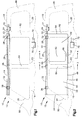
- an inflatable apparatus 10 helps to protect an occupant of a vehicle 12.
- the present invention is applicable to any inflatable apparatus that is inflatable between a vehicle occupant and a vehicle part in the event of a vehicle collision.
- a preferred embodiment of the apparatus 10 includes an inflatable vehicle occupant protection device in the form of an inflatable curtain 14 that is mounted adjacent the side structure 16 of the vehicle 12 and a roof 18 of the vehicle.
- the side structure 16 of the vehicle 12 includes side windows 20.
- An inflator 24 is connected in fluid communication with the inflatable curtain 14 through a fill tube 22.
- the inflator 24 contains a stored quantity of pressurized inflation fluid (not shown) for inflating the inflatable curtain 14.
- the fill tube 22 has a first portion 30 for receiving inflation fluid from the inflator 24.
- the fill tube 22 has a second portion 32 disposed in the inflatable curtain 14.
- the second portion 32 of the fill tube 22 has a plurality of openings (not shown) that provide fluid communication between the fill tube 22 and the inflatable curtain 14.
- the fill tube 22 helps to distribute the inflation fluid evenly along the length of the inflatable curtain 14 in order to help inflate and deploy the curtain evenly along its length.
- the fill tube 22 could be omitted, in which case the inflator 24 would be connected directly to the inflatable curtain 14.
- the apparatus 10 includes a housing 26 (Fig. 1) that stores the inflatable curtain 14 in a deflated condition.
- the fill tube 22, the deflated inflatable curtain 14, and housing 26 have an elongated configuration and extend along the vehicle roof 18 and along the side structure 16 of the vehicle 12 above the side windows 20.
- the roof 18 may be either a standard roof that is fixed in place or a convertible roof that can be moved or removed.
- the apparatus 10 includes means 28, such as clamps or brackets, that connect the fill tube 22 and the inflatable curtain 14 to the vehicle side structure 16. The means 28 may also help connect the inflatable curtain 14 to the fill tube 22.
- the inflatable curtain 14 comprises first and second panels 40 and 42 that are arranged in an overlying manner. Overlapping portions 44 of the first and second panels 40 and 42 are secured together by stitching 46 (Figs. 2 and 3) that extends along at least a portion of the perimeter 48 of the panels.
- the overlapping portions 44 could alternatively be secured together by means such as dielectric sealing, ultrasonic bonding, heat sealing, adhesives, or by weaving the panels 40 and 42 together.
- the perimeter 48 is defined at least partially by an upper edge 50 (Fig. 2) of the inflatable curtain 14, an opposite lower edge 52 of the curtain, and front and rear edges 54 and 56 of the curtain spaced apart horizontally along the upper and lower edges.
- the perimeter 48 defines an inflatable volume 58 of the inflatable curtain 14.
- the upper and lower edges 50 and 52 and the front and rear edges 54 and 56 are shown as being generally straight, the upper and lower edges could be curved or angled. The upper and lower edges 50 and 52 thus might intersect and eliminate either or both of the front and rear edges 54 and 56.
- the inflatable curtain 14 (Fig. 3) is formed from a sheet of material that is folded over to form the overlying first and second panels 40 and 42. It will be recognized by those skilled in the art, however, that the inflatable curtain 14 could have alternative constructions.
- the first and second panels 40 and 42 could be formed from separate sheets of material arranged in an overlying manner and secured together by stitching 46 that extends around the entire perimeter 48 of the panels.
- the first and second panels 40 and 42 may also be woven simultaneously and interwoven along their perimeters to form the inflatable curtain 14.
- the first and second panels 40 and 42 are constructed of a fabric, such as nylon, that is coated with a gas impermeable material, such as urethane or silicone. Other materials, such as elastomers, plastic films, or combinations thereof, may also be used to construct the inflatable curtain 14.
- the first and second panels 40 and 42 may also be formed of single or multi-layered sheets of material.
- the first and second panels 40 and 42 may be connected together by known means 60, such as stitching, dielectric sealing, ultrasonic bonding, heat sealing, adhesives, tethers, or interweaving the panels, to form a non-inflatable area 62 within the inflatable volume 58 (Fig. 2) of the inflatable curtain 14.
- a non-inflatable area 62 may be desirable in areas along the side structure 16 of the vehicle 12 where occupants are unlikely to come into contact with the side structure. This may help to reduce the amount of inflation fluid required to fill the inflatable curtain 14 and reduce the time required to inflate the curtain.
- Such a non-inflatable area 62 may also be desirable to help control the thickness of the inflatable curtain 14 and to define inflatable chambers of the curtain.
- the non-inflatable area 62 is generally rectangular. It will be recognized by those skilled in the art, however, that it may be desirable for the non-inflatable area 62 to have a different configuration, depending upon the particular design of the inflatable curtain 14, the shape of the vehicle 12 in which the apparatus 10 is being installed, and the desired shape of the inflatable portion(s) of the curtain.
- the non-inflatable area 62 could consist of linear connections in which the panels are interconnected along straight or curved lines, areas of connection in which the panels are interconnected in areas defined by straight or curved boundaries, or a combination of linear connections and area connections.
- the non-inflatable area 62 helps to define inflatable forward and rearward portions 64 and 66, respectively, of the inflatable volume 58 of the inflatable curtain 14.
- the forward and rearward portions 64 and 66 are connected in fluid communication with each other by passages 68 that extend along the upper and lower edges 50 and 52 of the inflatable curtain 14 between the respective upper and lower edges and the non-inflatable area 62.
- the forward and rearward portions 64 and 66 may not be connected in fluid communication with each other.
- the forward portion 64 is positioned forwardly in the vehicle 12, between the side structure 16 of the vehicle and any occupant seated forwardly in the vehicle.
- the inflated rearward portion 66 is positioned rearwardly in the vehicle 12, between the side structure 16 of the vehicle and any occupant seated rearwardly in the vehicle.
- the inflator 24 may have any construction suitable for storing pressurized inflation fluid for inflating the inflatable curtain 14.
- An example of one such suitable construction is illustrated in Fig. 5.
- the inflator 24 includes a container 100 made of a suitable material, such as steel or aluminum.
- the container 100 includes a generally cylindrical side wall 102 defining a tubular container portion extending along a longitudinal central axis 104 between first and second open ends 106 and 108, respectively, of the tubular container portion.
- the container 100 further includes an end cap 110 secured to the first end 106 by any suitable means, such as a weld.
- the container 100 also includes an end plug 112 secured to the second end 108 by any suitable means, such as a weld.
- the end cap 110 includes a burst disk 114.
- the side wall 102, the end cap 110, the burst disk 114 and the end plug 112 cooperate to define a closed chamber 116 in the container 100.
- A. supply of inflation fluid 118 for inflating the inflatable curtain 14 is stored in the chamber 116.
- the end cap 110 includes a first cylindrical wall 120 having a first diameter and a second cylindrical wall 122 having a second, smaller diameter.
- the cylindrical walls 120 and 122 are coaxial with the side wall 102.
- the first cylindrical wall 120 has the same inner and outer diameter as the side wall 102.
- An annular end wall 124 extends perpendicular to axis 104 between and connecting the first and second cylindrical walls 120 and 122.
- the second cylindrical wall 122 has a cylindrical inner surface 130 and a cylindrical outer surface 132 parallel to the inner surface.
- the inner surface 130 of the second cylindrical wall 122 defines a central passage 138 in the end cap 110 of the container 100.
- the burst disk 114 is secured to an annular surface 134 surrounding the central passage 138 by any suitable means, such as a weld, to block the central passage.
- a plurality of cylindrical surfaces 140 extend radially between the inner surface 130 and the outer surface 132 of the second cylindrical wall 122 of the end cap 110 to define a plurality of inflation fluid passages 142.
- the passages 142 provide fluid communication between the central passage 138 and the fill tube 22.
- the central passage 138 when not blocked by the burst disk 114, provides fluid communication between the passages 142 and the chamber 116.
- the second cylindrical wall 122 supports an initiator 150 including initiation means 152, such as a squib, for rupturing the burst disk 114.
- initiation means 152 such as a squib
- the initiator 150 also includes terminal posts 154 operatively connected to lead wires 72 which provide a signal for actuating the initiator.
- the vehicle 12 includes a sensor mechanism 70 (shown schematically in Figs. 1 and 2) for sensing a side impact to the vehicle 12 and/or a rollover of the vehicle 12.
- the sensor mechanism 70 actuates the inflator 24 in response to the sensing of a side impact or a vehicle rollover by sending a signal via the lead wires 72 to the inflator.
- the sensor mechanism 70 provides an electrical signal over the lead wires 72 to the initiator 150 (Fig. 5).
- the means 152 is actuated, which causes the burst disk 114 to rupture in a known manner. Rupture of the burst disk 114 enables the stored gas 118 to flow out of the chamber 116 through the central passage 138 and the passages 142 into the fill tube 22.
- the fill tube 22 directs the inflation fluid into the inflatable curtain 14.
- the inflatable curtain 14 inflates under the pressure of the inflation fluid from the inflator 24.
- the housing 26 opens and the inflatable curtain 14 (Fig. 2) inflates away from the roof 18 in a downward direction as shown in the drawings and in a downward direction with respect to the direction of forward travel of the vehicle 12 into the position illustrated in Fig. 2.
- the inflatable curtain 14 when inflated, extends along the side structure 16 of the vehicle 12 and is positioned between the side structure and any occupant of the vehicle.
- the first panel 40 is positioned adjacent the side structure 16 of the vehicle 12.
- the upper edge 50 of the inflatable curtain 14 is positioned adjacent the intersection of the roof 18 and the side structure 16 of the vehicle 12.
- the front edge 54 of the inflatable curtain 14 is positioned adjacent an A pillar 80 of the vehicle 12.
- the rear edge 56 of the inflatable curtain 14 is positioned adjacent a C pillar 82 of the vehicle 12.
- the inflatable curtain 14 extends between the A pillar 80 and the C pillar 82 of the vehicle 12 and overlies at least a portion of the A pillar, C pillar, and a B pillar 84 of the vehicle.
- the inflatable curtain may have alternative configurations.
- the inflatable curtain 14 extends between the A pillar 80 and the C pillar 82 of the vehicle 12.
- the inflatable curtain 14 could, however, extend between the A pillar 80 and the B pillar 84 only or between the B pillar and the C pillar 82 only.
- the inflatable curtain 14 could, when inflated, extend between the A pillar 80 and a D pillar 86 of the vehicle 12.
- the inflatable curtain 14 when inflated, helps to protect a vehicle occupant in the event of a vehicle rollover or a side impact to the vehicle 12.
- the non-inflatable portion 62 helps to limit the thickness of the inflated inflatable curtain 14 and helps to reduce the overall volume of the curtain.
- the forward and rearward portions 64 and 66 when inflated, help to absorb the energy of impacts with the inflatable curtain 14 and help to distribute the impact energy over a large area of the curtain.
- the passages 68 also help to distribute the impact energy over a large area of the inflatable curtain 14 by allowing inflation fluid to move between the forward and rearward portions 64 and 66 upon impacts with the curtain.
- the inflation fluid in the curtain is maintained at a desired pressure in order to help prevent vehicle occupants from penetrating through the curtain.
- penetrating through it is meant that the pressure of the inflation fluid in the inflatable curtain is insufficient to prevent an occupant from moving the first and second panels together upon striking the curtain, in which case the occupant essentially strikes the side structure 16 of the vehicle 12.
- the inflation pressure should remain at or above a desired pressure, preferably 160 kilopascals (kPa) absolute, for a predetermined period of time, preferably at least about the first 5-7 seconds of inflation.
- the desired pressure could, however, be higher or lower depending upon factors such as the volume of the inflatable curtain 14 and the thickness of the curtain when inflated.
- the inflator 24 In order to achieve the desired pressure in the inflatable curtain 14 when the curtain is initially inflated, the inflator 24 must deliver a given amount of inflation fluid to the curtain. This amount depends on the volume of the inflatable curtain 14.
- the inflator 24 is a stored gas inflator containing compressed inflation fluid at about 3500-7500 psig, preferably at about 6250 psig.
- the preferred inflator In order to achieve the desired pressure in an inflatable curtain having a volume in the range of 12-50 liters, the preferred inflator must deliver about 0.7-3.3 moles of inflation fluid.
- an inflatable curtain having a volume of about 27 liters may require about 2.2 moles of inflation fluid in order to achieve a desired inflation pressure.
- the apparatus 10 may experience leakage of inflation fluid prior to actuation of the inflator 24, during inflation of the inflatable curtain 14, or after the curtain is inflated.
- inflation fluid Prior to actuation of the inflator 24, inflation fluid may leak extremely slowly from the inflator over a long period of time, e.g., over a period of years. This is because a perfect seal at such high pressures is difficult to achieve.
- leakage may be experienced at leakage points, such as hardware connections (e.g., at the locations where the curtain is clamped to the fill tube 22), or through the curtain itself. This is also the case after the inflatable curtain 14 is inflated.
- the amount of inflation fluid delivered to the inflatable curtain 14 must account for losses due to leakage, curtain stretching/expansion, and other reasons. This is especially true when using an inflation fluid comprising a gas having a low atomic weight, such as helium, because such gasses flow more easily through the leakage points than gasses having higher atomic weights. Therefore, leakage and other losses are taken into account when sizing the inflator 24, i.e., extra inflation fluid may be included in order to account for potential inflation fluid losses. Also, additional sealing means may be applied to the inflatable curtain 14 and any connections between the curtain and the inflator 24 and/or fill tube 22 where leakage may occur. Those skilled in the art, however, will appreciate that it may be desirable to avoid the need for such additional sealing means.
- the inflator 24 is a stored gas inflator containing inflation fluid in the form of a mixture of helium gas and nitrogen gas stored under pressure. No other forms of inflation fluid are stored in the inflator 24, and the inflator does not include any other types of material, such as pyrotechnic material, for generating inflation fluid.
- the inflation fluid consists essentially of 65-95% helium gas and 5-35% nitrogen gas, by volume.
- the inflation fluid consists essentially of 85-95% helium gas and 5-15% nitrogen gas. More specifically, the inflation fluid preferably consists essentially of about 90% helium gas and about 10% nitrogen gas.
- the nitrogen gas included in the inflation fluid helps to compensate for effects caused by the low atomic weight of helium. Nitrogen gas has about 7 times the mass of helium. Therefore, the inflation fluid, consisting essentially of a mixture of helium and nitrogen, will flow more slowly through leakage points or the inflatable curtain 14 than an inflation fluid consisting essentially of helium alone. The helium/nitrogen inflation fluid mixture also will have a lesser tendency to leak from the inflator 24 prior to actuation of the inflator. The helium/nitrogen inflation fluid mixture of the present invention thus helps eliminate the need for additional sealing means that might otherwise be required if using helium alone as an inflation fluid.
- the helium/nitrogen inflation fluid mixture will also flow more slowly from the inflator 24 through the fill tube 22 and into the inflatable curtain 14.
- the structure of the apparatus 10 can, however, be adapted to compensate for the slower fluid flow by sizing the fill tube 22 and/or the openings in the fill tube to deliver the desired amount of inflation fluid to the inflatable curtain 14 in the desired amount of time.
- the inflator 24 When the inflator 24 is actuated, there is a large pressure differential between the compressed inflation fluid in the inflator and the gas occupying the fill tube 22.
- the size of the inflator 24 and/or the fill tube 22 is selected such that the inflation fluid accelerates from the inflator 24 into the fill tube 22 and achieves sonic flow, i.e., reaches a supersonic velocity.
- the inflation fluid slows to a velocity below supersonic speed as pressure builds in the fill tube.
- a large pressure differential is created between the tube and the inflatable curtain 14. This causes the inflation fluid to reach a supersonic velocity as the fluid enters the inflatable curtain 14 through the outlet apertures.
- supersonic velocity it is meant that the velocity is above that of the speed of sound in a given medium.
- speed of sound of the helium/nitrogen inflation fluid mixture will be a given velocity at a given temperature.
- a supersonic velocity of the helium/nitrogen inflation fluid mixture at the given temperature would be above the given velocity for that temperature.
- a shock wave is created, which propagates back and forth along the length of the tube.
- fluid temperatures at the end of the tube opposite the inflator 24 can reach maximum temperatures in the range of 1000-1750 degrees Kelvin. These high fluid temperatures are a result of adiabatic compressive heating of air that is in the fill tube 22 prior to actuation of the inflator 24 and isentropic heating of the inflation fluid and air mixture as the shock wave passes through the fluid media in the tube.
- the fluid gains heat thermodynamically from the tube, which results in higher pressures in the inflatable curtain 14 for a given amount of inflation fluid.
- ambient temperature is defined as 295° K, which is equal to about 22° C or 71.6° F.
- the fluid quickly cools to a temperature just above ambient temperature. This helps to ensure that the desired pressure of the inflation fluid in the inflatable volume 58 of the inflatable curtain 14 is maintained.
- the temperature of the inflation fluid in the inflatable curtain 14, being just above ambient temperature will be less susceptible to pressure loss due to thermodynamic heat loss. For example, if the inflation fluid in the inflatable curtain 14 were at a significantly higher temperature than the ambient temperature, the inflation fluid pressure in the curtain would decrease as the fluid is cooled.
- the above-listed results are achieved by using the helium/nitrogen inflation fluid mixture of the present invention in conjunction with the apparatus 10, which is constructed to deliver the required amount of inflation fluid to the inflatable curtain 14 in the required amount of time.
- the fill tube 22 is constructed to deliver the required amount of inflation fluid to the inflatable curtain 14 in the required amount of time.
- the use of the pressurized inflation fluid having the helium/nitrogen composition disclosed herein is thus critical to the present invention.
- the inflatable curtain 14 has a volume of about 27 liters. About 2.2 moles of the helium/nitrogen inflation fluid mixture are required to inflate the inflatable curtain 14 to the required pressure (at or above 160 kPa absolute) in the required time (20-30 ms).
- the inflator 24 and fill tube 22 are sized so as to provide the helium/nitrogen inflation fluid mixture to the inflatable curtain 14 at a molar flow rate sufficient to inflate the curtain to the desired pressure in the required time.
- the inflator 24 stores the helium/nitrogen inflation fluid mixture at about 6250 psig and the fill tube 22 is sized to deliver the inflation fluid at a molar flow rate sufficient to fill the inflatable curtain 14 to the required pressure in the required amount of time.
- the cross-sectional flow area of the tube, the number of openings in the tube, and the size/spacing of the openings are selected to provide the amount of inflation fluid required to inflate the inflatable curtain 14 to the desired pressure in the required time.
- the cross-sectional flow area of the fill tube 22 is also sized so as to cause the helium/nitrogen inflation fluid mixture entering the inflatable curtain 14 to maintain supersonic velocity during deployment of the curtain.
- the helium/nitrogen inflation fluid mixture gains heat through compressive heating of the air in the fill tube 22, shock wave propagation/oscillation along the length of the fill tube, and thermodynamic heat transfer from the tube.
- the helium/nitrogen inflation fluid mixture enters the inflatable curtain 14, the fluid quickly cools to a temperature just above ambient temperature which, as stated above, helps to prevent pressure loss in the curtain.
- inflation fluids having a helium/nitrogen inflation fluid mixture in which the helium is provided in a proportion less than that of the inflation fluid of the present invention will not produce the inflation time, pressure, and temperature described above because an overabundance of nitrogen gas would help prevent the inflation fluid from achieving sonic flow.
- inflation fluids having a helium/nitrogen inflation fluid mixture in which the nitrogen is provided in a proportion less than that of the inflation fluid of the present invention will not produce the reduced leakage described herein.
- Helium having a low molecular weight, has a relatively high sonic flow rate compared to other gasses. Thus, at a given temperature, helium will flow through the fill tube and into the inflatable curtain 14 faster than a gas having a higher molecular weight.
- the helium/nitrogen inflation fluid mixture of the present invention including helium in a large proportion, thus realizes these advantages.
- Gasses other than helium have low sonic flow rates compared to helium. Such gasses, if used alone in a stored gas inflator, would not produce the required flow into the inflatable curtain 14 to inflate the device to the required pressure in the required time without some form of augmentation, such as added heat. Such gasses, if used in a stored gas inflator without augmentation, would thus be incapable of achieving the desired results of inflating the inflatable curtain 14 to the desired pressure in the required time.
- the nitrogen included in the helium/nitrogen inflation fluid mixture lowers the sonic flow rate of the inflation fluid. Nonetheless, the helium/nitrogen inflation fluid mixture in the proportions disclosed in the present invention will not lower the sonic flow rate to a level where the required molar flow rate of the inflation fluid cannot be achieved using the apparatus 10 of the disclosed construction.
- the helium/nitrogen inflation fluid mixture of the present invention will permit the inflator 24 and/or fill tube 22 to have a construction appropriately selected to deliver the required molar flow rate of inflation fluid to the inflatable curtain 14 so that the curtain is inflated in the required amount of time.
- the critical temperature and critical pressure of helium (-267° C and 33.8 psia, respectively) and the critical temperature and critical pressure of nitrogen (-147° C and 492 psia, respectively) are low as compared to other gasses. This helps to ensure that the inflation fluid will remain in a gaseous state throughout inflation. Other gasses having higher critical temperatures and pressures may require augmentation, such as added heat, in order to ensure that the inflation fluid will remain in a gaseous state throughout inflation.
- the physical properties of helium are such that helium gains and loses heat quickly in comparison to other gases.
- the helium/nitrogen inflation fluid mixture also loses heat quickly when it enters the inflatable curtain 14 and quickly cools to a temperature just above ambient temperature.
- the inflatable curtain 14 will experience a smaller amount of pressure loss over time due to cooling of the helium/nitrogen inflation fluid mixture.
- nitrogen will not gain or lose heat as quickly as helium, the relatively low proportion of nitrogen in the helium/nitrogen inflation fluid mixture will not detract substantially from the results provided by the helium in the mixture.
Landscapes
- Physics & Mathematics (AREA)
- Fluid Mechanics (AREA)
- Engineering & Computer Science (AREA)
- Mechanical Engineering (AREA)
- Air Bags (AREA)
Abstract
Description
Claims (6)
- Apparatus for helping to protect an occupant of a vehicle, said apparatus comprising:an inflatable vehicle occupant protection device that is inflatable into a position between a vehicle part and a vehicle occupant; andan inflation fluid source that provides inflation fluid for inflating said inflatable vehicle occupant protection device, said inflation fluid source containing a stored inflation fluid consisting essentially of 65-95% helium gas and 5-35% nitrogen gas stored under pressure.
- The apparatus as recited in claim 1, wherein said inflation fluid source preferably has a stored inflation gas consisting essentially of 80-95% helium gas and 5-15% nitrogen gas stored under pressure.
- The apparatus as recited in claim 1, wherein said inflation fluid source preferably has a stored inflation gas consisting essentially of about 90% helium gas and about 10% nitrogen gas stored under pressure.
- Apparatus as recited in claim 1, wherein said inflatable vehicle occupant protection device comprises an inflatable curtain inflatable away from a roof of the vehicle roof into a position between a side structure of the vehicle and a vehicle occupant.
- The apparatus as recited in claim 4, further comprising a fill tube for delivering said inflation fluid from said inflation fluid source to said inflatable curtain, said fill tube having a portion disposed in said inflatable curtain.
- The apparatus as recited in claim 4, wherein said inflation fluid source inflates said inflatable vehicle occupant protection device to a predetermined pressure and maintains said inflatable vehicle occupant protection device at or above said predetermined pressure for at least 5-7 seconds.
Applications Claiming Priority (4)
| Application Number | Priority Date | Filing Date | Title |
|---|---|---|---|
| US65227701A | 2001-09-27 | 2001-09-27 | |
| US965277 | 2001-09-27 | ||
| US652277 | 2001-09-27 | ||
| US09/965,277 US6554315B2 (en) | 2001-09-27 | 2001-09-27 | Inflatable vehicle occupant protection device |
Publications (2)
| Publication Number | Publication Date |
|---|---|
| EP1300301A2 true EP1300301A2 (en) | 2003-04-09 |
| EP1300301A3 EP1300301A3 (en) | 2004-05-19 |
Family
ID=27760666
Family Applications (1)
| Application Number | Title | Priority Date | Filing Date |
|---|---|---|---|
| EP02019928A Withdrawn EP1300301A3 (en) | 2001-09-27 | 2002-09-04 | Inflatable vehicle occupant protection device |
Country Status (2)
| Country | Link |
|---|---|
| US (1) | US6554315B2 (en) |
| EP (1) | EP1300301A3 (en) |
Cited By (1)
| Publication number | Priority date | Publication date | Assignee | Title |
|---|---|---|---|---|
| WO2003101791A1 (en) * | 2002-05-31 | 2003-12-11 | Autoliv Asp, Inc. | Tuning the performance of compressed gas-containing inflators |
Families Citing this family (11)
| Publication number | Priority date | Publication date | Assignee | Title |
|---|---|---|---|---|
| US6629703B2 (en) * | 2001-12-14 | 2003-10-07 | Breed Automotive Technology, Inc. | Opening device for a cold gas inflator |
| DE10240639B3 (en) * | 2002-09-03 | 2004-02-12 | Trw Airbag Systems Gmbh & Co. Kg | Vehicle airbag gas generator with long cylindrical casing, has external igniter units producing gas which flows into distribution chambers in cylinder |
| US20050242550A1 (en) * | 2004-04-30 | 2005-11-03 | Macnee Arthur L | Automotive roof system with protective device |
| US7784822B2 (en) * | 2004-07-26 | 2010-08-31 | Nxgen Technologies, Inc. | Inflatable airbag |
| JP2006056308A (en) | 2004-08-18 | 2006-03-02 | Daicel Chem Ind Ltd | Inflator |
| US7338073B2 (en) * | 2004-08-18 | 2008-03-04 | Daicel Chemical Industries, Ltd. | Inflator |
| US20110057425A1 (en) * | 2005-07-26 | 2011-03-10 | Fink Michael F | Side curtain airbag |
| US7905516B2 (en) * | 2006-05-19 | 2011-03-15 | Tk Holdings Inc. | Airbag module with integrated gas generation |
| SE532177C2 (en) | 2006-07-24 | 2009-11-10 | P & P Ab | A puncture device for an inflatable unit |
| WO2012151261A2 (en) | 2011-05-02 | 2012-11-08 | Nxgen | Side curtain airbag and method and appartus for manufacturing a side curtain airbag |
| DE102015014797A1 (en) * | 2015-11-14 | 2017-05-18 | Hydac Technology Gmbh | safety device |
Family Cites Families (20)
| Publication number | Priority date | Publication date | Assignee | Title |
|---|---|---|---|---|
| US4981534B1 (en) | 1990-03-07 | 1997-02-04 | Atlantic Res Corp | Occupant restraint system and composition useful therein |
| US5172598A (en) | 1991-02-28 | 1992-12-22 | General Motors Corporation | Stored gas inflatable restraint inflation system |
| SE9103649D0 (en) | 1991-12-10 | 1991-12-10 | Aga Ab | FILLING OF AIR CUSHION |
| US5551723A (en) * | 1994-07-20 | 1996-09-03 | Breed Automotive Technology, Inc. | Pulse shaping for airbag inflators |
| US5433476A (en) * | 1994-07-27 | 1995-07-18 | Breed Automotive Technology, Inc. | Temperature compensated stored gas inflator |
| US5564740A (en) | 1995-03-09 | 1996-10-15 | Trw Inc. | Air bag inflator |
| US5678856A (en) * | 1995-06-28 | 1997-10-21 | Trw Inc. | Exploding foil initiator for air bag inflator |
| US5605349A (en) * | 1995-12-21 | 1997-02-25 | Kaiser Aluminum & Chemical Corporation | Integrated canister for an airbag inflator |
| US5826904A (en) | 1996-06-10 | 1998-10-27 | Morton International, Inc. | Directional compressed gas inflator |
| DE19739375B4 (en) * | 1997-09-09 | 2005-07-28 | Welz Industrieprodukte Gmbh | Opening device for a gas pressure tank of an airbag |
| US6161481A (en) | 1998-02-26 | 2000-12-19 | Trw Inc. | Air bag inflator |
| US6145876A (en) * | 1998-10-23 | 2000-11-14 | Oea, Inc. | Vehicle inflator with stored gas for supplementing inflation |
| US6412811B1 (en) * | 1999-02-26 | 2002-07-02 | Trw Inc. | Inflator |
| US6177365B1 (en) | 1999-06-17 | 2001-01-23 | Milliken & Company | Two-layered coating system for airbag fabrics |
| US6177366B1 (en) | 1999-06-17 | 2001-01-23 | Milliken & Company | Two-layer coating system for airbag fabrics |
| US6220309B1 (en) | 1999-09-24 | 2001-04-24 | Milliken & Company | Inflatable fabrics comprising basket-woven attachment points between fabric panels |
| US6431595B1 (en) * | 1999-12-22 | 2002-08-13 | Trw Inc. | Long duration air bag inflator |
| US6244623B1 (en) | 2000-02-02 | 2001-06-12 | Autoliv Asp, Inc. | Flow-open inflator |
| US6237940B1 (en) | 2000-02-29 | 2001-05-29 | Trw Inc. | Inflator for side curtain |
| US6726243B2 (en) * | 2002-05-31 | 2004-04-27 | Autoliv Asp, Inc. | Tuning the performance of compressed gas-containing inflators |
-
2001
- 2001-09-27 US US09/965,277 patent/US6554315B2/en not_active Expired - Lifetime
-
2002
- 2002-09-04 EP EP02019928A patent/EP1300301A3/en not_active Withdrawn
Cited By (2)
| Publication number | Priority date | Publication date | Assignee | Title |
|---|---|---|---|---|
| WO2003101791A1 (en) * | 2002-05-31 | 2003-12-11 | Autoliv Asp, Inc. | Tuning the performance of compressed gas-containing inflators |
| US6726243B2 (en) | 2002-05-31 | 2004-04-27 | Autoliv Asp, Inc. | Tuning the performance of compressed gas-containing inflators |
Also Published As
| Publication number | Publication date |
|---|---|
| US20030057684A1 (en) | 2003-03-27 |
| US6554315B2 (en) | 2003-04-29 |
| EP1300301A3 (en) | 2004-05-19 |
Similar Documents
| Publication | Publication Date | Title |
|---|---|---|
| EP1398226B1 (en) | Inflation assembly for variable profile air bag | |
| US6471240B2 (en) | Inflatable side curtain | |
| US6565118B2 (en) | Folded inflatable curtain | |
| JP4377488B2 (en) | Inflator with multiple detonators | |
| US5301979A (en) | Piston driven cold gas air bag inflator | |
| US6554315B2 (en) | Inflatable vehicle occupant protection device | |
| EP1286856B2 (en) | Vehicle inflator for generating shock wave that opens burst disc | |
| JP5123262B2 (en) | Device for inflating an inflatable device | |
| US6409211B1 (en) | Inflatable side curtain | |
| US7192052B2 (en) | Inflation assembly with extended filling capability | |
| JPH06508320A (en) | Hybrid airbag inflator | |
| JPH06316247A (en) | Gas expansion equipment | |
| US6428037B1 (en) | Inflatable curtain | |
| US6231073B1 (en) | Inflatable side curtain | |
| US6336654B1 (en) | Inflatable side curtain | |
| US7252303B2 (en) | Inflator | |
| US6296274B1 (en) | Apparatus for inflating a side curtain | |
| US7163230B2 (en) | Inflatable side curtain with fill tube | |
| US6250667B1 (en) | Inflatable side curtain | |
| KR20010029518A (en) | Apparatus for protecting a vehicle occupant | |
| US6883830B2 (en) | Pressurized medium for inflator | |
| JP2002145004A (en) | Inflator | |
| WO2003028875A1 (en) | Inflator-use pressurizing medium | |
| US20080042407A1 (en) | Extended output inflator device |
Legal Events
| Date | Code | Title | Description |
|---|---|---|---|
| PUAI | Public reference made under article 153(3) epc to a published international application that has entered the european phase |
Free format text: ORIGINAL CODE: 0009012 |
|
| AK | Designated contracting states |
Kind code of ref document: A2 Designated state(s): AT BE BG CH CY CZ DE DK EE ES FI FR GB GR IE IT LI LU MC NL PT SE SK TR Designated state(s): AT BE BG CH CY CZ DE DK EE ES FI FR GB GR IE IT LI LU MC NL PT SE SK TR |
|
| AX | Request for extension of the european patent |
Extension state: AL LT LV MK RO SI |
|
| RAP1 | Party data changed (applicant data changed or rights of an application transferred) |
Owner name: TRW AUTOMOTIVE U.S. LLC |
|
| PUAL | Search report despatched |
Free format text: ORIGINAL CODE: 0009013 |
|
| AK | Designated contracting states |
Kind code of ref document: A3 Designated state(s): AT BE BG CH CY CZ DE DK EE ES FI FR GB GR IE IT LI LU MC NL PT SE SK TR |
|
| AX | Request for extension of the european patent |
Extension state: AL LT LV MK RO SI |
|
| 17P | Request for examination filed |
Effective date: 20041115 |
|
| AKX | Designation fees paid |
Designated state(s): DE ES FR IT |
|
| 17Q | First examination report despatched |
Effective date: 20050217 |
|
| GRAP | Despatch of communication of intention to grant a patent |
Free format text: ORIGINAL CODE: EPIDOSNIGR1 |
|
| STAA | Information on the status of an ep patent application or granted ep patent |
Free format text: STATUS: THE APPLICATION IS DEEMED TO BE WITHDRAWN |
|
| 18D | Application deemed to be withdrawn |
Effective date: 20070717 |