EP1300210A2 - Manufacturing method and composite powder metal rotor assembly for surface type permanent magnet machine - Google Patents
Manufacturing method and composite powder metal rotor assembly for surface type permanent magnet machine Download PDFInfo
- Publication number
- EP1300210A2 EP1300210A2 EP02078754A EP02078754A EP1300210A2 EP 1300210 A2 EP1300210 A2 EP 1300210A2 EP 02078754 A EP02078754 A EP 02078754A EP 02078754 A EP02078754 A EP 02078754A EP 1300210 A2 EP1300210 A2 EP 1300210A2
- Authority
- EP
- European Patent Office
- Prior art keywords
- powder metal
- ferromagnetic powder
- disk
- magnetically
- segment
- Prior art date
- Legal status (The legal status is an assumption and is not a legal conclusion. Google has not performed a legal analysis and makes no representation as to the accuracy of the status listed.)
- Withdrawn
Links
Images





Classifications
-
- H—ELECTRICITY
- H02—GENERATION; CONVERSION OR DISTRIBUTION OF ELECTRIC POWER
- H02K—DYNAMO-ELECTRIC MACHINES
- H02K1/00—Details of the magnetic circuit
- H02K1/06—Details of the magnetic circuit characterised by the shape, form or construction
- H02K1/22—Rotating parts of the magnetic circuit
- H02K1/27—Rotor cores with permanent magnets
- H02K1/2706—Inner rotors
- H02K1/272—Inner rotors the magnetisation axis of the magnets being perpendicular to the rotor axis
- H02K1/274—Inner rotors the magnetisation axis of the magnets being perpendicular to the rotor axis the rotor consisting of two or more circumferentially positioned magnets
- H02K1/2753—Inner rotors the magnetisation axis of the magnets being perpendicular to the rotor axis the rotor consisting of two or more circumferentially positioned magnets the rotor consisting of magnets or groups of magnets arranged with alternating polarity
- H02K1/278—Surface mounted magnets; Inset magnets
- H02K1/2781—Magnets shaped to vary the mechanical air gap between the magnets and the stator
-
- B—PERFORMING OPERATIONS; TRANSPORTING
- B22—CASTING; POWDER METALLURGY
- B22F—WORKING METALLIC POWDER; MANUFACTURE OF ARTICLES FROM METALLIC POWDER; MAKING METALLIC POWDER; APPARATUS OR DEVICES SPECIALLY ADAPTED FOR METALLIC POWDER
- B22F7/00—Manufacture of composite layers, workpieces, or articles, comprising metallic powder, by sintering the powder, with or without compacting wherein at least one part is obtained by sintering or compression
- B22F7/06—Manufacture of composite layers, workpieces, or articles, comprising metallic powder, by sintering the powder, with or without compacting wherein at least one part is obtained by sintering or compression of composite workpieces or articles from parts, e.g. to form tipped tools
-
- H—ELECTRICITY
- H02—GENERATION; CONVERSION OR DISTRIBUTION OF ELECTRIC POWER
- H02K—DYNAMO-ELECTRIC MACHINES
- H02K1/00—Details of the magnetic circuit
- H02K1/02—Details of the magnetic circuit characterised by the magnetic material
-
- H—ELECTRICITY
- H02—GENERATION; CONVERSION OR DISTRIBUTION OF ELECTRIC POWER
- H02K—DYNAMO-ELECTRIC MACHINES
- H02K15/00—Processes or apparatus specially adapted for manufacturing, assembling, maintaining or repairing of dynamo-electric machines
- H02K15/02—Processes or apparatus specially adapted for manufacturing, assembling, maintaining or repairing of dynamo-electric machines of stator or rotor bodies
- H02K15/03—Processes or apparatus specially adapted for manufacturing, assembling, maintaining or repairing of dynamo-electric machines of stator or rotor bodies having permanent magnets
-
- Y—GENERAL TAGGING OF NEW TECHNOLOGICAL DEVELOPMENTS; GENERAL TAGGING OF CROSS-SECTIONAL TECHNOLOGIES SPANNING OVER SEVERAL SECTIONS OF THE IPC; TECHNICAL SUBJECTS COVERED BY FORMER USPC CROSS-REFERENCE ART COLLECTIONS [XRACs] AND DIGESTS
- Y10—TECHNICAL SUBJECTS COVERED BY FORMER USPC
- Y10T—TECHNICAL SUBJECTS COVERED BY FORMER US CLASSIFICATION
- Y10T29/00—Metal working
- Y10T29/49—Method of mechanical manufacture
- Y10T29/49002—Electrical device making
- Y10T29/49009—Dynamoelectric machine
-
- Y—GENERAL TAGGING OF NEW TECHNOLOGICAL DEVELOPMENTS; GENERAL TAGGING OF CROSS-SECTIONAL TECHNOLOGIES SPANNING OVER SEVERAL SECTIONS OF THE IPC; TECHNICAL SUBJECTS COVERED BY FORMER USPC CROSS-REFERENCE ART COLLECTIONS [XRACs] AND DIGESTS
- Y10—TECHNICAL SUBJECTS COVERED BY FORMER USPC
- Y10T—TECHNICAL SUBJECTS COVERED BY FORMER US CLASSIFICATION
- Y10T29/00—Metal working
- Y10T29/49—Method of mechanical manufacture
- Y10T29/49002—Electrical device making
- Y10T29/49009—Dynamoelectric machine
- Y10T29/49012—Rotor
-
- Y—GENERAL TAGGING OF NEW TECHNOLOGICAL DEVELOPMENTS; GENERAL TAGGING OF CROSS-SECTIONAL TECHNOLOGIES SPANNING OVER SEVERAL SECTIONS OF THE IPC; TECHNICAL SUBJECTS COVERED BY FORMER USPC CROSS-REFERENCE ART COLLECTIONS [XRACs] AND DIGESTS
- Y10—TECHNICAL SUBJECTS COVERED BY FORMER USPC
- Y10T—TECHNICAL SUBJECTS COVERED BY FORMER US CLASSIFICATION
- Y10T29/00—Metal working
- Y10T29/49—Method of mechanical manufacture
- Y10T29/49002—Electrical device making
- Y10T29/4902—Electromagnet, transformer or inductor
- Y10T29/49075—Electromagnet, transformer or inductor including permanent magnet or core
-
- Y—GENERAL TAGGING OF NEW TECHNOLOGICAL DEVELOPMENTS; GENERAL TAGGING OF CROSS-SECTIONAL TECHNOLOGIES SPANNING OVER SEVERAL SECTIONS OF THE IPC; TECHNICAL SUBJECTS COVERED BY FORMER USPC CROSS-REFERENCE ART COLLECTIONS [XRACs] AND DIGESTS
- Y10—TECHNICAL SUBJECTS COVERED BY FORMER USPC
- Y10T—TECHNICAL SUBJECTS COVERED BY FORMER US CLASSIFICATION
- Y10T29/00—Metal working
- Y10T29/49—Method of mechanical manufacture
- Y10T29/49002—Electrical device making
- Y10T29/4902—Electromagnet, transformer or inductor
- Y10T29/49075—Electromagnet, transformer or inductor including permanent magnet or core
- Y10T29/49076—From comminuted material
Definitions
- This invention relates generally to permanent magnet machines, and more particularly, to the manufacture of surface permanent magnet rotors for a permanent magnet machine.
- Adhesive bond lines between laminations and between permanent magnets and the rotor cores are subject to failure during operation. Moreover, motor or generator heating and environmental conditions degrade the integrity of the adhesive, potentially leading to eventual magnet separation and rotor failure.
- a thin retaining cylinder usually of metallic or wound fibrous construction.
- the use of such a thin retaining cylinder does have detrimental effects on machine performance and efficiency.
- the required cylinder thickness for a larger high speed motor or generator can make the use of such a can for these applications impractical.
- Permanent magnets embedded in the steel core are retained by thin webs stamped into the lamination material. Determining the width of the thin webs involves a trade-off concerning flux leakage versus structural integrity. Making the web wider allows for higher speed operation and greater rotor robustness at the expense of greater flux leakage, more magnet cost, and lower machine output and efficiency.
- the present invention provides a composite powder metal disk for a rotor assembly in a permanent magnet machine, the disk having an inner annular magnetically conducting segment of soft ferromagnetic powder metal compacted and sintered to a high density.
- the disk further comprises an outer annular permanent magnet segment of alternating polarity permanent magnets.
- the permanent magnet segment may be a continuous magnet ring with regions of alternating polarity around the circumference of the disk or may be discrete permanent magnets separated from each other by spaces or by non-ferromagnetic powder metal segments pressed and sintered to a high density.
- a rotor assembly is provided having a plurality of the composite powder metal disks axially stacked along and mounted to a shaft.
- the permanent magnets may be hard ferromagnetic powder metal pressed and sintered with the soft ferromagnetic and optional non-ferromagnetic powder metal, or may be prefabricated magnets adhesively affixed in the disks after sintering the powder metal portions. These disks are then stacked axially along a shaft with their magnetic patterns aligned to form the powder metal rotor assembly.
- a permanent magnet machine incorporating the powder metal rotor assembly of the present invention is simpler to manufacture and at a lower cost than prior surface permanent magnet rotors.
- the present invention provides composite powder metal rotor components for rotor assemblies in surface permanent magnet machines.
- Permanent magnet machines incorporating the composite powder metal components exhibit high power density and efficiency and high speed rotating capability.
- a plurality of powder metal disks or laminations are fabricated to comprise an inner annular magnetically conducting segment and an outer annual permanent magnet segment or ring.
- the magnetically conducting segment comprises a pressed and sintered soft ferromagnetic powder metal.
- the soft ferromagnetic powder metal is nickel, iron, cobalt or an alloy thereof.
- this soft ferromagnetic metal is a low carbon steel or a high purity iron powder with a minor addition of phosphorus, such as covered by MPIF (Metal Powder Industry Federation) Standard 35 F-0000, which contains approximately 0.27% phosphorus.
- MPIF Metal Powder Industry Federation
- AISI 400 series stainless steels are magnetically conducting, and may be used in the present invention.
- the permanent magnet segment or ring comprises a series of alternating polarity permanent magnets, such as ferrite or rare earth permanent magnets. Depending on the particular machine, it is within the skill of one in the art to determine the appropriate number and size of permanent magnets to be spaced around the exterior circumferential surface of the disk.
- the permanent magnet segment is a continuous magnet ring of pressed and sintered hard ferromagnetic powder metal, which is subsequently magnetized to create regions of alternating polarity around the entire surface.
- the permanent magnet segment is a plurality of discrete permanent magnets spaced apart by air gaps that extend from the inner annular magnetically conducting segment to the edge of the disk.
- the discrete permanent magnets comprise pressed and sintered hard ferromagnetic powder metal.
- the permanent magnet segment is a plurality of discrete permanent magnets spaced apart by magnetically non-conducting segments comprising pressed and sintered non-ferromagnetic powder metal.
- the permanent magnets may be either prefabricated magnets affixed to the inner annular segment and the magnetically non-conducting segments, or pressed and sintered hard ferromagnetic powder metal.
- the non-ferromagnetic powder metal is austenitic stainless steel, such as SS316.
- austenitic stainless steel such as SS316.
- the AISI 300 series stainless steels are non-magnetic and may be used in the present invention.
- the AISI 8000 series steels are non-magnetic and may be used.
- the soft ferromagnetic metal of the inner annular magnetically conducting segment and the non-ferromagnetic metal in the outer annular permanent magnet segment are chosen so as to have similar densities and sintering temperatures, and are approximately of the same strength, such that upon compaction and sintering, the materials behave in a similar fashion.
- the soft ferromagnetic powder metal is Fe-0.27%P and the non-ferromagnetic powder metal is SS316.
- the inner annular magnetically conducting segment may optionally further comprise a magnetically non-conducting insert positioned to surround a shaft in the rotor assembly.
- This insert comprises non-ferromagnetic powder metal as described above in the permanent magnet segment.
- the insert functions to insulate the hub and shaft from magnetic flux.
- the insert may further have a star-shaped configuration designed to enhance the flux between the magnets, as will be shown and described further below.
- the powder metal disks of the present invention typically exhibit a magnetically conducting segment having at least about 95% of theoretical density, and typically between about 95%-98% of theoretical density.
- Wrought steel or iron has a theoretical density of about 7.85 gms/cm 3 , and thus, the magnetically conducting segment exhibits a density of around 7.46-7.69 gms/cm 3 .
- the non-conducting segments of the powder metal disks of certain embodiments of the present invention exhibit a density of at least about 85% of theoretical density, which is on the order of about 6.7 gms/cm 3 . Thus, the non-ferromagnetic powder metals are less compactible then the ferromagnetic powder metals.
- the pressed and sintered hard ferromagnetic powder metal magnets of certain embodiments of the present invention exhibit a density of at least about 95.5% ⁇ 3.5% of theoretical density, depending on fill factor, which is on the order of about 3.8-7.0 gms/cm 3 .
- the powder metal disks or rings can essentially be of any thickness. These disks are aligned axially along a shaft and mounted to the shaft to form a rotor assembly.
- the shaft is typically equipped with a key and the individual disks have a keyway on an interior surface to align the disks to the shaft upon pressing the part to the shaft.
- the individual disks or rings have a thickness on the order of about ⁇ to ⁇ inches. As disk thicknesses increase, the boundaries between the powder metal conducting segment, the powder metal non-conducting segments or inserts, and the powder metal permanent magnets may begin to blur. In practice, up to 13 disks of the present invention having a ⁇ - ⁇ inch thickness are suitable for forming a rotor assembly.
- each disk or the number of disks that may be utilized to construct a rotor assembly there is, however, no limit to the thickness of each disk or the number of disks that may be utilized to construct a rotor assembly.
- the individual disks are aligned with respect to each other along the shaft such that the magnetic flux paths are aligned along the shaft.
- the non-ferromagnetic powder metal acts as an insulator between the aligned flux paths comprised of the soft ferromagnetic powder metal segment and the permanent magnets, and increases the structural stability of the assembly. This arrangement allows better direction of magnetic flux and improves the torque of the rotor assembly.
- FIGS. 1 and 2 depict in perspective view and plan view, respectively, a powder metal rotor assembly 10 of the present invention having a plurality of powder metal composite disks 12 stacked along a shaft 14, each disk 12 having an inner annular magnetically conducting segment 16 and an outer annular permanent magnet segment 18 comprising a plurality of alternating polarity permanent magnets 20.
- the disks are aligned from one disk 12 to another along the length of the shaft 14.
- the permanent magnet segment 18 includes magnetically non-conducting segments 22 separating the permanent magnets 20.
- the non-conducting segments 22 provide insulation that directs the magnetic flux from one permanent magnet 20 to the next alternating polarity permanent magnet 20.
- the permanent magnets may be comprised of powder metal pressed sequentially or concurrently with the powder metals used to form the inner annular magnetically conducting segment 16 and the non-conducting segments 22.
- the permanent magnets may be prefabricated and inserted into spaces between the non-conducting segments 22. The prefabricated magnets may be adhesively affixed within the spaces, and this structure has improved structural stability as a result of the adjacent non-conducting segments. A retaining cylinder could also be used.
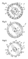
- FIG. 3 depicts a disk similar in configuration to that depicted in FIGS. 1 and 2, but includes a magnetically non-conducting insert 24 in the inner annular segment 16.
- Insert 24 has an essentially star-shaped configuration and extends from the interior surface 26 of the disk 12 into tip portions 24a or 24b that terminate at (24a) or near (24b) a respective permanent magnet 20 in the outer annular permanent magnet segment 18.
- the magnetically conducting portion 16a of the inner annular magnetically conducting segment 16 directs magnetic flux from one permanent magnet 20 to the next alternating polarity permanent magnet 20.
- the insert 24 further blocks magnetic flux from being channeled toward the shaft 14.
- the composite powder metal disk 12 is similar to that depicted in FIGS. 1 and 2, but the disk 12 further includes an inner annular non-conducting segment 25 adjacent the interior surface 26 of the disk 12. As with the insert 24 of FIG. 3, insert 25 blocks magnetic flux from being channeled into the shaft 14.
- FIG. 4 also depicts a higher number of smaller permanent magnets 20 separated by thinner non-conducting segments 22 as compared to FIGS. 1 and 2.
- FIG. 5 depicts another embodiment of a disk 12 of the present invention having an inner annular magnetically conducting segment 16 and an outer annular permanent magnet segment 18 comprising a ring of hard ferromagnetic powder metal magnetized to create a plurality of alternating polarity permanent magnets 20 substantially continuously around the entire disk 12. It should be understood by one skilled in the art that small magnetically dead regions (not shown) may occur between magnet poles. Nonetheless, the embodiment of FIG. 5 provides a simple construction having a strong magnet layer.
- FIG. 6 depicts yet another alternative embodiment of a disk 12 of the present invention having an inner annular magnetically conducting segment 16 and an outer annular permanent magnet segment 18 comprising a plurality of discrete alternating polarity powder metal permanent magnets 20 separated by spaces or air gaps 28.
- This embodiment is magnetically equivalent to the embodiment of FIGS. 1 and 2, as air is non-conducting, but lacks the added structural stability provided by the powder metal non-conducting segments 22.
- FIGS. 1-6 depict various embodiments for a surface permanent magnet rotor, it should be appreciated that numerous other embodiments exist having a varying number of permanent magnets 20, and having various sizes of permanent magnets 20, as well as varying sizes for the air gaps 28 separating the permanent magnets 20, as in FIG. 6, or the size of the non-conducting segments 22 separating the permanent magnets 20, as in FIGS. 1-4. Thus, the invention should not be limited to the particular embodiments shown in FIGS. 1-6. It should be further understood that each embodiment described as a disk 12 could be formed as a ring, which is generally understood to have a smaller annular width and larger inner diameter than a disk.
- disk used throughout the description of the invention and in the claims hereafter is hereby defined to include a ring. Further, the term disk includes solid disks.
- the aperture in the center of the disk that receives the rotor shaft may be later formed, for example, by machining.
- the present invention further provides a method for fabricating composite powder metal disks or rings for assembling into a rotor for a surface permanent magnet machine.
- a disk-shaped die is provided having discrete regions in a pattern corresponding to the desired rotor magnetic configuration.
- An inner annular region is filled with a soft ferromagnetic powder metal to ultimately form the inner annular magnetically conducting segment of the rotor.
- a plurality of discrete regions are filled with non-ferromagnetic powder metal to ultimately form the magnetically non-conducting segments of the rotor.
- Inserts may be used to form spaces in which prefabricated permanent magnets may later be affixed.
- the permanent magnets comprise hard ferromagnetic powder metal
- an outer annular region or a plurality of discrete regions are filled with the hard ferromagnetic powder metal. Inserts may be used to maintain spaces between the magnets for air gaps.
- the powder metals are pressed in the die to form a compacted powder metal disk. This compacted powder metal is then sintered to form a powder metal disk or lamination having an inner annual region of magnetically conducting material and an outer annular region of permanent magnets and optional non-conducting powder metal or air gaps, the disk exhibiting high structural stability.
- the pressing and sintering process results in a magnetically conducting segment having a density of at least 95% of theoretical density, permanent magnets having a density of at least about 95.5% ⁇ 3.5% of theoretical density (depending on fill factor) and optional non-conducting segments having a density of at least 85% of theoretical density.
- the method for forming these rotors provides increased mechanical integrity, reduced flux leakage, more efficient flux channeling, reduced cost and simpler construction.
- a non-ferromagnetic powder metal is filled into the die in a desired pattern in the inner annular region to ultimately form the non-conducting inserts, as described above.
- the method of the present invention may thus include filling a die with two or three dissimilar powder metals. At the least, the die is partially filled in an inner annular portion with a soft ferromagnetic powder metal.
- the die may also be filled with a non-ferromagnetic powder metal in regions of one or both the inner annular portion and an outer annular portion of the die.
- the die may be filled with a hard ferromagnetic powder metal in all or portions of the outer annular portion of the die.
- the regions in the die are filled concurrently with the various powder metals, which are then concurrently pressed and sintered.
- the regions are filled sequentially with the powder metal being pressed and then sintered after each filling step. In other words, one powder metal is filled, pressed and sintered, and then the second powder metal is filled and the entire assembly is pressed and sintered, and then the optional third powder metal is filled and the entire assembly is pressed and sintered.
- the pressing of the filled powder metal may be accomplished by uni-axially pressing the powder in a die, for example at a pressure of about 45-50 tsi. It should be understood that the pressure needed is dependent upon the particular powder metal materials that are chosen.
- the pressing of the powder metal involves heating the die to a temperature in the range of about 275°F (135°C) to about 290°F (143°C), and heating the powders within the die to a temperature about 175°F (79°C) to about 225°F (107°C).
- the sintering of the pressed powder comprises heating the compacted powder metal to a first temperature of about 1400°F (760°C) and holding at that temperature for about one hour.
- the powder metal includes a lubricating material, such as a plastic, on the particles to increase the strength of the material during compaction.
- the internal lubricant reduces particle-to-particle friction, thus allowing the compacted powder to achieve a higher green strength after sintering.
- the lubricant is then burned out of the composite during this initial sintering operation, also known as a de-lubrication or delubing step.
- a delubing for one hour is a general standard practice in the industry and it should be appreciated that times above or below one hour are sufficient for the purposes of the present invention if delubrication is achieved thereby.
- the temperature may be varied from the general industry standard if the ultimate delubing function is performed thereby.
- the sintering temperature is raised to a full sintering temperature, which is generally in the industry about 2050°F (1121°C). During this full sintering, the compacted powder shrinks, and particle-to-particle bonds are formed, generally between iron particles.
- Standard industry practice involves full sintering for a period of one hour, but it should be understood that the sintering time and temperature may be adjusted as necessary.
- the sintering operation may be performed in a vacuum furnace, and the furnace may be filled with a controlled atmosphere, such as argon, nitrogen, hydrogen or combinations thereof.
- a controlled atmosphere such as argon, nitrogen, hydrogen or combinations thereof.
- the sintering process may be performed in a continuous belt furnace, which is also generally provided with a controlled atmosphere, for example a hydrogen/nitrogen atmosphere such as 75% H 2 / 25% N 2 .
- Other types of furnaces and furnace atmospheres may be used within the scope of the present invention as determined by one skilled in the art.
- FIGS. 7-11C depict die inserts, hopper configurations and pressing techniques that may be used to achieve the concurrent filling or sequential filling of the powder metals and subsequent compaction to form the composite powder metal disks of the present invention. It is to be understood, however, that these illustrations are merely examples of possible methods for carrying out the present invention.
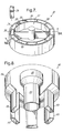
- FIG. 7 depicts a die insert 30 that may be placed within a die cavity to produce the powder metal disk 12 of FIGS. 1 and 2 in which the permanent magnets are prefabricated and affixed in the composite disk after compaction and sintering of the powder metals.
- the two powder metals i.e. the soft ferromagnetic and non-ferromagnetic powder metals, are filled concurrently or sequentially into the separate insert cavities 32,34, and then the insert 30 is removed.
- Spacing inserts 36 may be placed in cavities 38 to form spaces between the non-conducting segments 22 into which the permanent magnets 20 may subsequently be inserted and affixed.
- FIG. 8 depicts a hopper assembly 40 that may be used to fill the insert 30 of FIG.
- an inner bowl 42 is provided having an annular tube 44 for forming the inner annular conducting segment 16 of the composite part or metal disk 12 of FIGS. 1 and 2.
- This inner bowl 42 is adapted to hold and deliver the soft ferromagnetic powder metal.
- An outer bowl 46 is positioned around the inner bowl 42, with a plurality of tubes 48 for forming the spaced non-conducting segments 22 in the outer annular permanent magnet segment 18. This outer bowl 46 is adapted to hold and deliver non-ferromagnetic powder metal.
- This dual hopper assembly 40 enables either concurrent or sequential filling of the die insert of FIG. 7.
- FIGS. 9A-9E depict schematic views in partial cross-section taken along line 9A-9A of FIG. 7 of how the die insert 30 of FIG. 7 and the hopper assembly 40 of FIG. 8 can be used with an uniaxial die press 50 to produce the composite powder metal disk 12 of FIGS. 1 and 2.
- the die insert 30 is placed within a cavity 52 in the die 54, as shown in FIG. 9A, with a lower punch 56 of the press 50 abutting the bottom 30a of the insert 30.
- the hopper assembly 40 is placed over the insert 30 and the powder metals 33,35 are filled into the insert cavities 32,34, concurrently or sequentially, as shown in FIG. 9B.
- the hopper assembly 40 is then removed, leaving a filled insert 30 in the die cavity 52, as shown in FIG.
- the first powder is poured into either the inner bowl 42 or outer bowl 46, and a specially configured upper punch 58 is lowered so as to press the filled powder, and the partially filled and compacted insert (not shown) is sintered.
- the second fill is then effected and the insert 30 removed for pressing, ejection and sintering of the complete part 60.
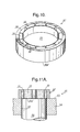
- FIG. 10 depicts an alternative die insert 30N that may be placed on a top surface 55 of the die 54 over the die cavity 52 to form the powder metal disk 12 depicted in FIG. 5.
- the die insert 30N has an inner annular cavity for forming the inner annular conducting segment 16 and a single cavity (not shown) or plurality of outer annular cavities 38 for forming the outer annular permanent magnet segment 18.
- the hopper assembly 40 of FIG. 8 would differ in that the outer bowl 46 could form a single ring around the inner bowl 42 rather than having discrete tubes 48. The outer bowl would hold and deliver the hard ferromagnetic powder metal.
- FIGS. 11A-11C show the method for using the insert 30N of FIG. 10.
- the insert is set on top surface 55 of the die 54 over the cavity 52 with the lower punch 56 in the ejection position, as shown in FIG. 11A.
- the powder metals 33,39 are then filled into the insert 30N, either concurrently or sequentially, similarly to the filling operation shown in FIG. 9B, and the lower punch 56 is then lowered to the fill position.
- the lowering of the punch 56 forms a vacuum which pulls the powder metals 33,39 out of the bottom 30aN of the insert 30N and into the die cavity 52, as shown in FIG. 11B.
- the insert 30N is then removed from the top surface 55 of the die 54, and the upper punch 58 is lowered into the die cavity 52 to compact the powder metals 33,39.
- the lower punch 56 is then raised to eject the final composite part 60, as shown in FIG. 11C, and the part 60 is then transferred to a sintering furnace (not shown).
- the outer annular permanent magnet segment 18 is subsequently magnetized to create the regions of alternating polarity, i.e. the permanent magnets 20.
- pneumatic air hammers or tappers may be placed on, in, or around the inserts 30,30N used in either the method depicted in FIGS. 9A-9E or the method depicted in FIGS. 11A-11C.
- the vibrating of the insert 30,30N enables the powder metal 33,35,39 to flow out of the insert 30,30N with greater ease as the insert 30,30N is removed, and further enables a greater tap density.
- a dry lube is sprayed or added to the inside of the insert cavities 32,34,38 used in either of those methods. Again, this dry lube helps to improve the flow of the powder metals 33,35,39 out of the insert 30,30N.
- heaters and thermocouples may be used in conjunction with the insert 30,30N.
- the heat keeps the powder warm, if warm compaction is being optimized, and again allows the powder metals 33,35,39 to more easily flow out of the insert 30,30N.
- the composite part may be formed as a solid disk, with the aperture being machined after compaction or sintering.
- the outer annular segment 18 may be first formed as a solid ring of pressed and sintered non-ferromagnetic powder metal, then machined to form spaces into which permanent magnets may be inserted.
- a three-hopper assembly may be used to achieve a tri-fill process.
- the tri-fill process can include concurrent filling of the powder metals or sequential filling of the powder metals.
Landscapes
- Engineering & Computer Science (AREA)
- Power Engineering (AREA)
- Manufacturing & Machinery (AREA)
- Mechanical Engineering (AREA)
- Composite Materials (AREA)
- Materials Engineering (AREA)
- Chemical & Material Sciences (AREA)
- Manufacture Of Motors, Generators (AREA)
- Permanent Field Magnets Of Synchronous Machinery (AREA)
- Powder Metallurgy (AREA)
- Manufacturing Cores, Coils, And Magnets (AREA)
- Iron Core Of Rotating Electric Machines (AREA)
- Hard Magnetic Materials (AREA)
Abstract
Description
Claims (83)
- A method of making a powder metal rotor for a surface permanent magnet machine, the method comprising:filling an inner annular region (32) of a disk-shaped die (30) with a soft ferromagnetic powder metal (33);filling discrete regions (34) within an outer annular region of the die (30) with a non-ferromagnetic powder metal (35) so as to leave spaces (38) between each discrete region (34);pressing the powders (33,35) in the die (30) to form a compacted powder metal disk (60);sintering the compacted powder metal disk (60); andproviding permanent magnets (20) in the spaces (38) between the discrete regions (34) of the outer annular region in an arrangement of alternating polarity to form a composite powder metal disk (12) having an inner annular magnetically conducting segment (16) and an outer annular segment (18) of a plurality of alternating polarity permanent magnets (20) separated by magnetically non-conducting segments (22).
- The method of claim 1, wherein the inner annular region (32) and discrete regions (34) are filled concurrently.
- The method of claim 1, wherein the inner annular region (32) and discrete regions (34) are filled sequentially with the powder metal (33,35) being pressed and sintered after each filling step.
- The method of claim 1, wherein the providing of permanent magnets (20) includes affixing prefabricated permanent magnets (20) to the inner annular segment (16) and to adjacent magnetically non-conducting segments (22).
- The method of claim 1, wherein the providing of permanent magnets (20) includes filling the spaces (38) between each discrete region (34) with a hard ferromagnetic powder metal (39), pressing the hard ferromagnetic powder metal (39) and sintering the pressed powder.
- The method of claim 5, wherein the inner annular region (32), discrete regions (34) and spaces (38) are filled concurrently.
- The method of claim 5, wherein the inner annular region (32), discrete regions (34) and spaces (38) are filled sequentially with the powder metal (33,35,39) being pressed and sintered after each filling step.
- The method of claim 1, wherein the soft ferromagnetic powder metal (33) is Ni, Fe, Co or an alloy thereof.
- The method of claim 1, wherein the soft ferromagnetic powder metal (33) is a high purity iron powder with a minor addition of phosphorus.
- The method of claim 1, wherein the non-ferromagnetic powder metal (35) is an austenitic stainless steel.
- The method of claim 1, wherein the non-ferromagnetic powder metal (35) is an AISI 8000 series steel.
- The method of claim 1, wherein the pressing comprises uniaxially pressing the powders (33,35) in the die (30).
- The method of claim 1, wherein the pressing comprises pre-heating the powders (33,35) and pre-heating the die (30).
- The method of claim 1, wherein, after the pressing, the compacted powder metal disk (60) is de-lubricated at a first temperature, followed by sintering at a second temperature greater than the first temperature.
- The method of claim 1, wherein the sintering is performed in a vacuum furnace having a controlled atmosphere.
- The method of claim 1, wherein the sintering is performed in a belt furnace having a controlled atmosphere.
- The method of claim 1, further comprising filling a portion of the inner annular region (32) in a desired pattern with a non-ferromagnetic powder metal (35), pressing the non-ferromagnetic powder metal (35), and sintering the pressed powder to form a inner magnetically non-conducting segment (24,25).
- The method of claim 1 further comprising stacking a plurality of the composite powder metal disks (12) axially along a shaft (14) to form a powder metal rotor assembly (10).
- A method of making a powder metal rotor for a surface permanent magnet machine, the method comprising:filling an inner annular region (32) of a disk-shaped die (30) with a soft ferromagnetic powder metal (33);pressing the soft ferromagnetic powder metal (33) in the die (30) to form a compacted magnetically conducting segment (16);sintering the compacted magnetically conducting segment (16);filling discrete regions (34) within an outer annular region of the die (30) with a non-ferromagnetic powder metal (35) so as to leave spaces (38) between each discrete region (34);pressing the non-ferromagnetic powder metal (35) in the die (30) to form a plurality of compacted magnetically non-conducting segments (22);sintering the compacted magnetically non-conducting segments (22) and the compacted and sintered conducting segment (16) to form a composite powder metal disk (12) having an inner annular magnetically conducting segment (16) and outer annularly spaced magnetically non-conducting segments (22); andproviding permanent magnets (20) in the spaces (38) between the magnetically non-conducting segments (22).
- The method of claim 19 further comprising affixing prefabricated permanent magnets (20) of alternating polarity between the spaced magnetically non-conducting segments (22).
- The method of claim 19 wherein the providing step comprises, after the second sintering step, filling the spaces (38) between the magnetically non-conducting segments (22) with a hard ferromagnetic powder metal (39), pressing the hard ferromagnetic powder metal (39) in the die (30) to form a plurality of compacted permanent magnet segments (20), and sintering the compacted permanent magnet segments (20) and the compacted and sintered conducting segment (16) and magnetically non-conducting segments (22) to form a composite powder metal disk (12) having an inner annular magnetically conducting segment (16) and outer annular alternating polarity permanent magnets (20) spaced by magnetically non-conducting segments (22).
- The method of claim 19, wherein the soft ferromagnetic powder metal (33) is Ni, Fe, Co or an alloy thereof.
- The method of claim 19, wherein the soft ferromagnetic powder metal (33) is a high purity iron powder with a minor addition of phosphorus.
- The method of claim 19, wherein the non-ferromagnetic powder metal (35) is an austenitic stainless steel.
- The method of claim 19, wherein the non-ferromagnetic powder metal (35) is an AISI 8000 series steel.
- The method of claim 19, wherein each pressing comprises uniaxially pressing the powder (33,35) in the die (30).
- The method of claim 19, wherein each pressing comprises pre-heating the powder (33,35) and pre-heating the die (30).
- The method of claim 19, wherein, after each pressing, the compacted segments (16,22) are de-lubricated at a first temperature, followed by sintering at a second temperature greater than the first temperature.
- The method of claim 19, wherein each sintering is performed in a vacuum furnace having a controlled atmosphere.
- The method of claim 19, wherein each sintering is performed in a belt furnace having a controlled atmosphere.
- The method of claim 19 further comprising stacking a plurality of the composite powder metal disks (12) axially along a shaft (14) to form a powder metal rotor assembly (10).
- A method of making a powder metal rotor for a surface permanent magnet machine, the method comprising:filling a disk-shaped die (30) in an inner annular region (32) with a soft ferromagnetic powder metal (33) and an outer annular region (38) with a hard ferromagnetic powder metal (39);pressing the powders (33,39) in the die (30) to form a compacted powder metal disk (60); andsintering the compacted powder metal disk (60) and magnetizing the hard ferromagnetic powder metal (39) to form a composite powder metal disk (12) having an inner annular magnetically conducting segment (16) and an outer annular segment (18) of alternating polarity permanent magnets (20).
- The method of claim 32 wherein the outer annular segment (18) comprises a continuous ring of hard ferromagnetic powder metal (39).
- The method of claim 32, wherein the outer annular region (38) is filled with the hard ferromagnetic powder metal (39) in discrete regions so as to leave gaps (34) therebetween.
- The method of claim 34, wherein the gaps (34) are filled with a non-ferromagnetic powder metal (35) which is then pressed and sintered to form magnetically non-conducting segments (22) between the permanent magnets (20).
- The method of claim 32, wherein the soft ferromagnetic powder metal (33) is Ni, Fe, Co or an alloy thereof.
- The method of claim 32, wherein the soft ferromagnetic powder metal (33) is a high purity iron powder with a minor addition of phosphorus.
- The method of claim 32, wherein the inner annular (32) and outer annular regions (38) are filled concurrently.
- The method of claim 32, wherein the inner annular (32) and outer annular regions (38) are filled sequentially with the powder metal (33,39) being pressed and sintered after each filling step.
- The method of claim 32, wherein the pressing comprises uniaxially pressing the powders (33,39) in the die (30).
- The method of claim 32, wherein the pressing comprises pre-heating the powders (33,39) and pre-heating the die (30).
- The method of claim 32, wherein, after the pressing, the compacted powder metal disk (60) is de-lubricated at a first temperature, followed by sintering at a second temperature greater than the first temperature.
- The method of claim 32, wherein the sintering is performed in a vacuum furnace having a controlled atmosphere.
- The method of claim 32, wherein the sintering is performed in a belt furnace having a controlled atmosphere.
- The method of claim 32 further comprising stacking a plurality of the composite powder metal disks (12) axially along a shaft (14) to form a powder metal rotor assembly (10).
- A powder metal disk (12) for a rotor assembly (10) in a surface permanent magnet machine, the disk (12) comprising an inner annular magnetically conducting segment (16) of pressed and sintered soft ferromagnetic powder metal (33), and an outer annular permanent magnet segment (18) comprising a plurality of alternating polarity permanent magnets (20).
- The disk (12) of claim 46, wherein the soft ferromagnetic powder metal (33) is Ni, Fe, Co or an alloy thereof.
- The disk (12) of claim 46, wherein the soft ferromagnetic powder metal (33) is a high purity iron powder with a minor addition of phosphorus.
- The disk (12) of claim 46, wherein the outer annular permanent magnet segment (18) further comprises a magnetically non-conducting segment (22) of pressed and sintered non-ferromagnetic powder metal (35) between each of the alternating polarity permanent magnets (20).
- The disk (12) of claim 49, wherein the non-ferromagnetic powder metal (35) is an austenitic stainless steel.
- The disk (12) of claim 49, wherein the non-ferromagnetic powder metal (35) is an AISI 8000 series steel.
- The disk (12) of claim 46, wherein the permanent magnets (20) comprise pressed and sintered hard ferromagnetic powder metal (39).
- The disk (12) of claim 46, wherein the permanent magnets (20) are prefabricated inserts adhesively bonded to the inner annular magnetically conducting segment (16).
- The disk (12) of claim 46, wherein the inner annular magnetically conducting segment (16) further comprises a substantially star-shaped magnetically non-conducting insert (24) of pressed and sintered non-ferromagnetic powder metal (35), with each tip portion (24a,24b) of the star-shaped insert (24) extending toward a respective permanent magnet (20) in the outer annular segment (18).
- The disk (12) of claim 46, wherein the alternating polarity permanent magnets (20) are discrete magnet segments separated by spaces (28).
- The disk (12) of claim 46 further comprising an inner annular magnetically non-conducting segment (25) of pressed and sintered non-ferromagnetic powder metal (35) radially inward of the inner annular magnetically conducting segment (16).
- A powder metal disk (12) for a rotor assembly (10) in a surface permanent magnet machine, the disk (12) comprising an inner annular magnetically conducting segment (16) of pressed and sintered soft ferromagnetic powder metal (33), and an outer annular permanent magnet segment (18) comprising a plurality of alternating polarity permanent magnets (20) separated by magnetically non-conducting segments (22) of pressed and sintered non-ferromagnetic powder metal (35).
- The disk (12) of claim 57, wherein the soft ferromagnetic powder metal (33) is Ni, Fe, Co or an alloy thereof.
- The disk (12) of claim 57, wherein the soft ferromagnetic powder metal (33) is a high purity iron powder with a minor addition of phosphorus.
- The disk (12) of claim 57, wherein the non-ferromagnetic powder metal (35) is an austenitic stainless steel.
- The disk (12) of claim 57, wherein the non-ferromagnetic powder metal (35) is an AISI 8000 series steel.
- The disk (12) of claim 57, wherein the permanent magnets (20) comprise pressed and sintered hard ferromagnetic powder metal (39).
- The disk (12) of claim 57, wherein the permanent magnets (20) are prefabricated inserts adhesively bonded to the inner annular magnetically conducting segment (16) and to the adjacent magnetically non-conducting segments (22).
- The disk (12) of claim 57, wherein the inner annular magnetically conducting segment (16) further comprises a substantially star-shaped magnetically non-conducting insert (24) of pressed and sintered non-ferromagnetic powder metal (35), with each tip portion (24a,24b) of the star-shaped insert (24) extending to a respective permanent magnet (20) in the outer annular segment (18).
- The disk (12) of claim 57, further comprising an inner annular magnetically non-conducting segment (25) of pressed and sintered non-ferromagnetic powder metal (35) radially inward of the inner annular magnetically conducting segment (16).
- A powder metal disk (12) for a rotor assembly (16) in a surface permanent magnet machine, the disk (12) comprising an inner annular magnetically conducting segment (16) of pressed and sintered soft ferromagnetic powder metal (33), and an outer annular permanent magnet segment (18) comprising a plurality of alternating polarity permanent magnets (20) of pressed and sintered hard ferromagnetic powder metal (39) separated by magnetically non-conducting segments (22) of pressed and sintered non-ferromagnetic powder metal (35).
- The disk (12) of claim 66, wherein the soft ferromagnetic powder metal (33) is Ni, Fe, Co or an alloy thereof.
- The disk (12) of claim 66, wherein the soft ferromagnetic powder metal (33) is a high purity iron powder with a minor addition of phosphorus.
- The disk (12) of claim 66, wherein the non-ferromagnetic powder metal (35) is an austenitic stainless steel.
- The disk (12) of claim 66, wherein the non-ferromagnetic powder metal (35) is an AISI 8000 series steel.
- The disk (12) of claim 66, wherein the inner annular magnetically conducting segment (16) further comprises a substantially star-shaped magnetically non-conducting insert (24) of pressed and sintered non-ferromagnetic powder metal (35), with each tip portion (24a,24b) of the star-shaped insert (24) extending to a respective permanent magnet (20) in the outer annular segment (18).
- The disk (12) of claim 66 further comprising an inner annular magnetically non-conducting segment (25) of pressed and sintered non-ferromagnetic powder metal (35) radially inward of the inner annular magnetically conducting segment (16).
- A powder metal rotor assembly (10) for a surface permanent magnet machine, comprising:a shaft (14); anda plurality of composite powder metal disks (12) axially stacked along and bonded to the shaft (14), each disk (12) comprising an inner annular magnetically conducting segment (16) of pressed and sintered soft ferromagnetic powder metal (33), and an outer annular permanent magnet segment (18) comprising a plurality of alternating polarity permanent magnets (20).
- The assembly (10) of claim 73, wherein the soft ferromagnetic powder metal (33) is Ni, Fe, Co or an alloy thereof.
- The assembly (10) of claim 73, wherein the soft ferromagnetic powder metal (33) is a high purity iron powder with a minor addition of phosphorus.
- The assembly (10) of claim 73, wherein the outer annular permanent magnet segment (18) further comprises a magnetically non-conducting segment (22) of pressed and sintered non-ferromagnetic powder metal (35) between each of the alternating polarity permanent magnets (20).
- The assembly (10) of claim 76, wherein the non-ferromagnetic powder metal (35) is an austenitic stainless steel.
- The assembly (10) of claim 76, wherein the non-ferromagnetic powder metal (35) is an AISI 8000 series steel.
- The assembly (10) of claim 73, wherein the permanent magnets (20) comprise pressed and sintered hard ferromagnetic powder metal (39).
- The assembly (10) of claim 73, wherein the permanent magnets (20) are prefabricated inserts adhesively bonded to the inner annular magnetically conducting segment (16).
- The assembly (10) of claim 73, wherein the inner annular magnetically conducting segment (16) further comprises a substantially star-shaped magnetically non-conducting insert (24) of pressed and sintered non-ferromagnetic powder metal (35), with each tip portion (24a,24b) of the star-shaped insert (24) extending to a respective permanent magnet (20) in the outer annular segment (18).
- The assembly (10) of claim 73, wherein the alternating polarity permanent magnets (20) are discrete magnet segments separated by spaces (28).
- The assembly (10) of claim 73 further comprising an inner annular magnetically non-conducting segment (25) of pressed and sintered non-ferromagnetic powder metal (35) radially inward of the inner annular magnetically conducting segment (16).
Applications Claiming Priority (2)
| Application Number | Priority Date | Filing Date | Title |
|---|---|---|---|
| US970223 | 2001-10-03 | ||
| US09/970,223 US6655004B2 (en) | 2001-10-03 | 2001-10-03 | Method of making a powder metal rotor for a surface |
Publications (2)
| Publication Number | Publication Date |
|---|---|
| EP1300210A2 true EP1300210A2 (en) | 2003-04-09 |
| EP1300210A3 EP1300210A3 (en) | 2005-11-02 |
Family
ID=25516610
Family Applications (1)
| Application Number | Title | Priority Date | Filing Date |
|---|---|---|---|
| EP02078754A Withdrawn EP1300210A3 (en) | 2001-10-03 | 2002-09-12 | Manufacturing method and composite powder metal rotor assembly for surface type permanent magnet machine |
Country Status (2)
| Country | Link |
|---|---|
| US (1) | US6655004B2 (en) |
| EP (1) | EP1300210A3 (en) |
Cited By (7)
| Publication number | Priority date | Publication date | Assignee | Title |
|---|---|---|---|---|
| EP1612913A3 (en) * | 2004-06-29 | 2006-03-29 | Nissan Motor Company, Limited | Permanent magnet rotor of an axial gap motor and manufacturing method |
| WO2007068515A1 (en) | 2005-12-14 | 2007-06-21 | Robert Bosch Gmbh | Rotor of an electrical machine, in particular of a motor, and method for producing a rotor |
| EP1722457A3 (en) * | 2005-05-10 | 2007-08-22 | Hitachi, Ltd. | Motor |
| EP2577687A1 (en) * | 2010-05-26 | 2013-04-10 | Tyco Electronics Corporation | Planar inductor devices |
| EP2605253A1 (en) * | 2011-12-13 | 2013-06-19 | Siemens Aktiengesellschaft | Manufacturing method for a permanent magnet, moulding system and permanent magnet |
| GB2482091B (en) * | 2009-09-21 | 2013-07-17 | Rod F Soderberg | A composite material including magnetic particles which provides structural and magnetic capabilities |
| EP3595136A1 (en) * | 2018-07-13 | 2020-01-15 | Siemens Aktiengesellschaft | Robust layers of material |
Families Citing this family (16)
| Publication number | Priority date | Publication date | Assignee | Title |
|---|---|---|---|---|
| US6889419B2 (en) * | 2002-04-16 | 2005-05-10 | Delphi Technologies, Inc. | Method of making a composite electric machine component of a desired magnetic pattern |
| US6857185B2 (en) * | 2002-05-24 | 2005-02-22 | Iap Research, Inc. | Method for electromagnetically joining tubes to sheets in a tubular heat transfer system |
| DE10307231A1 (en) * | 2003-02-14 | 2004-09-09 | Minebea Co., Ltd. | Brushless electric motor, has magnetic poles formed from magnetic molded body with terminating side on terminating body carrying magnetic poles |
| US20040166012A1 (en) * | 2003-02-21 | 2004-08-26 | Gay David Earl | Component having various magnetic characteristics and qualities and method of making |
| US7981359B2 (en) * | 2004-04-06 | 2011-07-19 | Hitachi Metals, Ltd. | Rotor and process for manufacturing the same |
| JP2007244151A (en) * | 2006-03-10 | 2007-09-20 | Jtekt Corp | motor |
| WO2010066251A1 (en) * | 2008-12-12 | 2010-06-17 | Sintex A/S | A permanent magnet rotor for a machine, a method for manufacturing a permanent magnet rotor and a manufacturing system |
| ITMI20121592A1 (en) * | 2012-09-25 | 2014-03-26 | Mavel Srl | METHOD FOR MANUFACTURING A ROTOR FOR ELECTRIC MOTORS AND ITS ROTOR |
| US10044238B2 (en) | 2016-04-13 | 2018-08-07 | Hamilton Sundstrand Corporation | Interior permanent magnet rotor hubs |
| CN106533006A (en) * | 2016-11-30 | 2017-03-22 | 浙江联宜电机有限公司 | High-speed brushless motor rotor |
| US10770936B2 (en) * | 2017-08-10 | 2020-09-08 | Hamilton Sundstrand Corporation | Modular permanent magnet rotor |
| JP6682601B2 (en) * | 2018-10-31 | 2020-04-15 | Ntn株式会社 | Molding method of green compact and manufacturing method of sintered bearing |
| US11692596B2 (en) * | 2020-09-25 | 2023-07-04 | Means Industries, Inc. | Axially oriented linear actuator including single stator coil, and clutch assembly having the actuator |
| US20230268814A1 (en) * | 2022-02-22 | 2023-08-24 | Borgwarner Inc. | Barrier coating for an electric motor rotor assembly |
| DE102022130644A1 (en) * | 2022-11-21 | 2024-05-23 | Dr. Ing. H.C. F. Porsche Aktiengesellschaft | Method for producing a permanent magnet electric motor |
| KR20260068378A (en) * | 2024-11-07 | 2026-05-14 | 한국재료연구원 | Permanent magnet assembly and its manufacturing method |
Family Cites Families (32)
| Publication number | Priority date | Publication date | Assignee | Title |
|---|---|---|---|---|
| US3670189A (en) * | 1971-04-30 | 1972-06-13 | Paul Peter Monroe | Gated permanent magnet motor |
| US3780418A (en) | 1972-10-10 | 1973-12-25 | Aluminum Co Of America | Method of fabricating composite multi-metallic billets useful for metal working operations |
| US3864154A (en) | 1972-11-09 | 1975-02-04 | Us Army | Ceramic-metal systems by infiltration |
| JPS57142798A (en) | 1981-02-26 | 1982-09-03 | Nippon Piston Ring Co Ltd | Powder molding method and molded article |
| US4602956A (en) | 1984-12-17 | 1986-07-29 | North American Philips Lighting Corporation | Cermet composites, process for producing them and arc tube incorporating them |
| FR2598641B1 (en) | 1986-05-16 | 1988-08-26 | Air Liquide | SINTERING PROCESS IN A CONTINUOUS OVEN OF POWDER MATERIAL |
| JPS6464548A (en) | 1987-09-03 | 1989-03-10 | Fanuc Ltd | Rotor construction of synchronous motor |
| DE3917277C2 (en) | 1989-05-24 | 1994-01-20 | Mannesmann Ag | Method and device for producing finished parts as a composite body made of powdery materials |
| SE501390C2 (en) | 1989-06-01 | 1995-01-30 | Abb Stal Ab | Method for making a compound tube with a durable outer layer |
| JPH0643100B2 (en) * | 1989-07-21 | 1994-06-08 | 株式会社神戸製鋼所 | Composite member |
| JPH0775205B2 (en) | 1989-07-21 | 1995-08-09 | 住友金属鉱山株式会社 | Method for producing Fe-P alloy soft magnetic sintered body |
| US5191256A (en) | 1989-12-15 | 1993-03-02 | American Motion Systems | Interior magnet rotary machine |
| US5371426A (en) | 1990-11-20 | 1994-12-06 | Seiko Epson Corporation | Rotor of brushless motor |
| JPH05315175A (en) * | 1992-05-14 | 1993-11-26 | Matsushita Electric Ind Co Ltd | Manufacture of magnetic circuit component and mold therefor |
| GB9311051D0 (en) | 1993-05-28 | 1993-07-14 | Brico Eng | Valve seat insert |
| JPH08138241A (en) * | 1994-11-04 | 1996-05-31 | Tdk Corp | Method of manufacturing magnetic recording medium |
| GB9501645D0 (en) | 1995-01-27 | 1995-03-15 | Atomic Energy Authority Uk | The manufacture of composite materials |
| JPH08331784A (en) | 1995-03-24 | 1996-12-13 | Hitachi Metals Ltd | Permanent magnet field type rotary machine |
| JPH08340666A (en) | 1995-06-12 | 1996-12-24 | Hitachi Metals Ltd | Metal powder composite sintered component, metal powder composite material extrusion molding apparatus, and metal powder composite material extrusion molding method |
| JP3705450B2 (en) * | 1995-09-20 | 2005-10-12 | 日立金属株式会社 | Method for manufacturing rotor core for reluctance motor |
| JPH09202905A (en) | 1996-01-24 | 1997-08-05 | Dainatsukusu:Kk | Method for manufacturing synchronizer ring by sintering |
| JP3690616B2 (en) * | 1996-04-15 | 2005-08-31 | 日立金属株式会社 | Rotating machine |
| US5722032A (en) * | 1996-07-01 | 1998-02-24 | General Motors Corporation | AC generator rotor segment |
| JP3308828B2 (en) | 1996-10-18 | 2002-07-29 | 株式会社日立製作所 | Permanent magnet rotating electric machine and electric vehicle using the same |
| US5801470A (en) | 1996-12-19 | 1998-09-01 | General Electric Company | Rotors with retaining cylinders and reduced harmonic field effect losses |
| EP0899049B1 (en) | 1997-01-20 | 2005-12-21 | Kabushiki Kaisha Meidensha | Unified junction structure of rare-earth magnet and metal material and the jointing method |
| US5820963A (en) * | 1997-04-02 | 1998-10-13 | Komag, Incorporated | Method of manufacturing a thin film magnetic recording medium having low MrT value and high coercivity |
| US5935722A (en) | 1997-09-03 | 1999-08-10 | Lockheed Martin Energy Research Corporation | Laminated composite of magnetic alloy powder and ceramic powder and process for making same |
| US6162552A (en) | 1998-12-03 | 2000-12-19 | General Electric Company | Rhenium-coated tungsten-based alloy and composite articles and method therefor |
| JP2001204146A (en) | 1999-11-08 | 2001-07-27 | Isuzu Motors Ltd | Rotor of rotating machine and method of manufacturing the same |
| US6287513B1 (en) | 1999-08-24 | 2001-09-11 | Delphi Technologies, Inc. | Method of shaping powder metal parts |
| US6423264B1 (en) * | 1999-10-14 | 2002-07-23 | Delphi Technologies, Inc. | Process for forming rotating electromagnets having soft and hard magnetic components |
-
2001
- 2001-10-03 US US09/970,223 patent/US6655004B2/en not_active Expired - Fee Related
-
2002
- 2002-09-12 EP EP02078754A patent/EP1300210A3/en not_active Withdrawn
Cited By (15)
| Publication number | Priority date | Publication date | Assignee | Title |
|---|---|---|---|---|
| EP1612913A3 (en) * | 2004-06-29 | 2006-03-29 | Nissan Motor Company, Limited | Permanent magnet rotor of an axial gap motor and manufacturing method |
| US7355311B2 (en) | 2004-06-29 | 2008-04-08 | Nissan Motor Co., Ltd. | Rotor of axial gap motor and method of producing same |
| CN100442637C (en) * | 2004-06-29 | 2008-12-10 | 日产自动车株式会社 | Rotor for axial gap motor and manufacturing method thereof |
| EP1722457A3 (en) * | 2005-05-10 | 2007-08-22 | Hitachi, Ltd. | Motor |
| US7906881B2 (en) | 2005-05-10 | 2011-03-15 | Hitachi, Ltd. | Motor |
| WO2007068515A1 (en) | 2005-12-14 | 2007-06-21 | Robert Bosch Gmbh | Rotor of an electrical machine, in particular of a motor, and method for producing a rotor |
| GB2482091B (en) * | 2009-09-21 | 2013-07-17 | Rod F Soderberg | A composite material including magnetic particles which provides structural and magnetic capabilities |
| EP2577687A1 (en) * | 2010-05-26 | 2013-04-10 | Tyco Electronics Corporation | Planar inductor devices |
| EP2605253A1 (en) * | 2011-12-13 | 2013-06-19 | Siemens Aktiengesellschaft | Manufacturing method for a permanent magnet, moulding system and permanent magnet |
| CN103157794A (en) * | 2011-12-13 | 2013-06-19 | 西门子公司 | Manufacturing method for a permanent magnet, moulding system and permanent magnet |
| WO2013087609A3 (en) * | 2011-12-13 | 2013-08-15 | Siemens Aktiengesellschaft | Manufacturing method for a permanent magnet, moulding system and permanent magnet |
| CN103157794B (en) * | 2011-12-13 | 2016-12-21 | 西门子公司 | Manufacture method, moulding system and permanent magnet for permanent magnet |
| EP3595136A1 (en) * | 2018-07-13 | 2020-01-15 | Siemens Aktiengesellschaft | Robust layers of material |
| WO2020011820A1 (en) * | 2018-07-13 | 2020-01-16 | Siemens Aktiengesellschaft | Robust material layers |
| US12046951B2 (en) | 2018-07-13 | 2024-07-23 | Siemens Aktiengesellschaft | Method for producing a magnetic material layer |
Also Published As
| Publication number | Publication date |
|---|---|
| EP1300210A3 (en) | 2005-11-02 |
| US6655004B2 (en) | 2003-12-02 |
| US20030062789A1 (en) | 2003-04-03 |
Similar Documents
| Publication | Publication Date | Title |
|---|---|---|
| US6856051B2 (en) | Manufacturing method and composite powder metal rotor assembly for circumferential type interior permanent magnet machine | |
| US6655004B2 (en) | Method of making a powder metal rotor for a surface | |
| US6675460B2 (en) | Method of making a powder metal rotor for a synchronous reluctance machine | |
| US20030062792A1 (en) | Manufacturing method and composite powder metal rotor assembly for spoke type interior permanent magnet machine | |
| US7146708B2 (en) | Method of making a composite electric machine rotor assembly | |
| US7148598B2 (en) | Spoke permanent magnet rotors for electrical machines and methods of manufacturing same | |
| US20030193258A1 (en) | Composite powder metal rotor sleeve | |
| US4942322A (en) | Permanent magnet rotor with bonded sheath | |
| US20030193260A1 (en) | Composite power metal stator sleeve | |
| US20030062786A1 (en) | Manufacturing method and composite powder metal rotor assembly for induction machine | |
| US7906881B2 (en) | Motor | |
| TWI391194B (en) | Stator compacted in one piece | |
| JP2004120892A (en) | Ring magnet, method of manufacturing the same, rotor and motor using the same | |
| CN114514679B (en) | Manufacturing synchronous reluctance machines using additive manufacturing | |
| WO2010084672A1 (en) | Dynamo electric machine | |
| US20050001499A1 (en) | Permanent magnet rotor for brushless D.C. motor | |
| JPH08256441A (en) | Permanent magnet rotor | |
| WO2005029677A2 (en) | Stator for an electric device | |
| JP2024534395A5 (en) | ||
| JP7608559B2 (en) | Gradient ring-shaped bonded magnet and manufacturing method thereof, and motor | |
| US20230291247A1 (en) | Electric motor | |
| JP2003260596A (en) | Method for producing compact by powder metallurgy, joining structure of compact, and rotor for motor | |
| JPH0726804Y2 (en) | Cylindrical outer peripheral multi-pole magnet | |
| JP4069040B2 (en) | Radially oriented ring magnet molding die and manufacturing method of radial oriented ring magnet | |
| JP2006060894A (en) | Dust core part and method for manufacturing the same, dust core and method for manufacturing the same, and mold |
Legal Events
| Date | Code | Title | Description |
|---|---|---|---|
| PUAI | Public reference made under article 153(3) epc to a published international application that has entered the european phase |
Free format text: ORIGINAL CODE: 0009012 |
|
| AK | Designated contracting states |
Kind code of ref document: A2 Designated state(s): AT BE BG CH CY CZ DE DK EE ES FI FR GB GR IE IT LI LU MC NL PT SE SK TR Designated state(s): AT BE BG CH CY CZ DE DK EE ES FI FR GB GR IE IT LI LU MC NL PT SE SK TR |
|
| AX | Request for extension of the european patent |
Extension state: AL LT LV MK RO SI |
|
| PUAL | Search report despatched |
Free format text: ORIGINAL CODE: 0009013 |
|
| AK | Designated contracting states |
Kind code of ref document: A3 Designated state(s): AT BE BG CH CY CZ DE DK EE ES FI FR GB GR IE IT LI LU MC NL PT SE SK TR |
|
| AX | Request for extension of the european patent |
Extension state: AL LT LV MK RO SI |
|
| RIC1 | Information provided on ipc code assigned before grant |
Ipc: 7H 02K 15/03 B Ipc: 7H 02K 1/27 B Ipc: 7H 02K 1/02 B Ipc: 7B 22F 7/06 A |
|
| 17P | Request for examination filed |
Effective date: 20060502 |
|
| AKX | Designation fees paid |
Designated state(s): DE FR GB |
|
| 17Q | First examination report despatched |
Effective date: 20070205 |
|
| GRAP | Despatch of communication of intention to grant a patent |
Free format text: ORIGINAL CODE: EPIDOSNIGR1 |
|
| STAA | Information on the status of an ep patent application or granted ep patent |
Free format text: STATUS: THE APPLICATION IS DEEMED TO BE WITHDRAWN |
|
| 18D | Application deemed to be withdrawn |
Effective date: 20071206 |