EP1299636B1 - Apparatus for the supply of fuel to an internal combustion engine, particularly for motor vehicles - Google Patents
Apparatus for the supply of fuel to an internal combustion engine, particularly for motor vehicles Download PDFInfo
- Publication number
- EP1299636B1 EP1299636B1 EP01947728A EP01947728A EP1299636B1 EP 1299636 B1 EP1299636 B1 EP 1299636B1 EP 01947728 A EP01947728 A EP 01947728A EP 01947728 A EP01947728 A EP 01947728A EP 1299636 B1 EP1299636 B1 EP 1299636B1
- Authority
- EP
- European Patent Office
- Prior art keywords
- fuel
- closure element
- pressure regulator
- passage
- configuration
- Prior art date
- Legal status (The legal status is an assumption and is not a legal conclusion. Google has not performed a legal analysis and makes no representation as to the accuracy of the status listed.)
- Expired - Lifetime
Links
- 239000000446 fuel Substances 0.000 title claims abstract description 38
- 238000002485 combustion reaction Methods 0.000 title claims description 8
- 239000002828 fuel tank Substances 0.000 claims abstract description 4
- 239000007788 liquid Substances 0.000 abstract 1
- 230000015572 biosynthetic process Effects 0.000 description 4
- 235000001674 Agaricus brunnescens Nutrition 0.000 description 1
- 230000003466 anti-cipated effect Effects 0.000 description 1
- 238000010276 construction Methods 0.000 description 1
- 210000005069 ears Anatomy 0.000 description 1
- 230000005405 multipole Effects 0.000 description 1
Images


Classifications
-
- F—MECHANICAL ENGINEERING; LIGHTING; HEATING; WEAPONS; BLASTING
- F02—COMBUSTION ENGINES; HOT-GAS OR COMBUSTION-PRODUCT ENGINE PLANTS
- F02M—SUPPLYING COMBUSTION ENGINES IN GENERAL WITH COMBUSTIBLE MIXTURES OR CONSTITUENTS THEREOF
- F02M37/00—Apparatus or systems for feeding liquid fuel from storage containers to carburettors or fuel-injection apparatus; Arrangements for purifying liquid fuel specially adapted for, or arranged on, internal-combustion engines
- F02M37/0047—Layout or arrangement of systems for feeding fuel
- F02M37/0052—Details on the fuel return circuit; Arrangement of pressure regulators
- F02M37/0058—Returnless fuel systems, i.e. the fuel return lines are not entering the fuel tank
-
- F—MECHANICAL ENGINEERING; LIGHTING; HEATING; WEAPONS; BLASTING
- F02—COMBUSTION ENGINES; HOT-GAS OR COMBUSTION-PRODUCT ENGINE PLANTS
- F02M—SUPPLYING COMBUSTION ENGINES IN GENERAL WITH COMBUSTIBLE MIXTURES OR CONSTITUENTS THEREOF
- F02M37/00—Apparatus or systems for feeding liquid fuel from storage containers to carburettors or fuel-injection apparatus; Arrangements for purifying liquid fuel specially adapted for, or arranged on, internal-combustion engines
- F02M37/04—Feeding by means of driven pumps
- F02M37/08—Feeding by means of driven pumps electrically driven
- F02M37/10—Feeding by means of driven pumps electrically driven submerged in fuel, e.g. in reservoir
- F02M37/103—Mounting pumps on fuel tanks
-
- F—MECHANICAL ENGINEERING; LIGHTING; HEATING; WEAPONS; BLASTING
- F02—COMBUSTION ENGINES; HOT-GAS OR COMBUSTION-PRODUCT ENGINE PLANTS
- F02M—SUPPLYING COMBUSTION ENGINES IN GENERAL WITH COMBUSTIBLE MIXTURES OR CONSTITUENTS THEREOF
- F02M37/00—Apparatus or systems for feeding liquid fuel from storage containers to carburettors or fuel-injection apparatus; Arrangements for purifying liquid fuel specially adapted for, or arranged on, internal-combustion engines
- F02M37/04—Feeding by means of driven pumps
- F02M37/08—Feeding by means of driven pumps electrically driven
- F02M37/10—Feeding by means of driven pumps electrically driven submerged in fuel, e.g. in reservoir
- F02M37/106—Feeding by means of driven pumps electrically driven submerged in fuel, e.g. in reservoir the pump being installed in a sub-tank
-
- F—MECHANICAL ENGINEERING; LIGHTING; HEATING; WEAPONS; BLASTING
- F02—COMBUSTION ENGINES; HOT-GAS OR COMBUSTION-PRODUCT ENGINE PLANTS
- F02M—SUPPLYING COMBUSTION ENGINES IN GENERAL WITH COMBUSTIBLE MIXTURES OR CONSTITUENTS THEREOF
- F02M37/00—Apparatus or systems for feeding liquid fuel from storage containers to carburettors or fuel-injection apparatus; Arrangements for purifying liquid fuel specially adapted for, or arranged on, internal-combustion engines
- F02M37/22—Arrangements for purifying liquid fuel specially adapted for, or arranged on, internal-combustion engines, e.g. arrangements in the feeding system
- F02M37/32—Arrangements for purifying liquid fuel specially adapted for, or arranged on, internal-combustion engines, e.g. arrangements in the feeding system characterised by filters or filter arrangements
-
- F—MECHANICAL ENGINEERING; LIGHTING; HEATING; WEAPONS; BLASTING
- F02—COMBUSTION ENGINES; HOT-GAS OR COMBUSTION-PRODUCT ENGINE PLANTS
- F02M—SUPPLYING COMBUSTION ENGINES IN GENERAL WITH COMBUSTIBLE MIXTURES OR CONSTITUENTS THEREOF
- F02M37/00—Apparatus or systems for feeding liquid fuel from storage containers to carburettors or fuel-injection apparatus; Arrangements for purifying liquid fuel specially adapted for, or arranged on, internal-combustion engines
- F02M37/0011—Constructional details; Manufacturing or assembly of elements of fuel systems; Materials therefor
- F02M37/0023—Valves in the fuel supply and return system
- F02M37/0029—Pressure regulator in the low pressure fuel system
-
- F—MECHANICAL ENGINEERING; LIGHTING; HEATING; WEAPONS; BLASTING
- F02—COMBUSTION ENGINES; HOT-GAS OR COMBUSTION-PRODUCT ENGINE PLANTS
- F02M—SUPPLYING COMBUSTION ENGINES IN GENERAL WITH COMBUSTIBLE MIXTURES OR CONSTITUENTS THEREOF
- F02M37/00—Apparatus or systems for feeding liquid fuel from storage containers to carburettors or fuel-injection apparatus; Arrangements for purifying liquid fuel specially adapted for, or arranged on, internal-combustion engines
- F02M37/0076—Details of the fuel feeding system related to the fuel tank
- F02M37/0082—Devices inside the fuel tank other than fuel pumps or filters
Definitions
- the present invention relates to apparatus for the supply of fuel to an internal combustion engine, in particular for a motor vehicle.
- JP 09 222 054 A proposes a system that can be used in both cases, with or without return flow, by changing location of the pressure regulator.
- the object of the present invention is therefore to provide fuel supply apparatus structured in such a way that, with a limited number of relatively simple operations it is possible to configure it for use in a fuel supply system of the type with return flow or for use in a fuel supply system without return flow.
- the apparatus 1 comprises a closure element 2 essentially in the form of a flanged plug, intended to be fixed in a liquid-tight manner in an aperture 3 ( Figures 4 and 5) formed in a lower wall 4a of a fuel tank 4.
- an aperture 3 Figures 4 and 5
- two mushroom shape retainer members 5 are formed in the face of the closure element intended to face into the tank.
- a further hollow tubular formation 9 extends in a similar manner from the closure element 2 towards the interior of the tank 4 (see Figures 2, 4 and 5) and its distal portion 9a is upwardly closed and shaped in the form of an hydraulic connector.
- a multi-pole electric connector 10 (Figure 3) is sealingly engaged in an aperture 11 (Figure 2) formed in the closure element 2.
- the apparatus 1 further comprises an electric pump 13 with a lower suction connector 13a, and an upper delivery connector 13b ( Figure 2).
- One end of a tube 14 is engaged on this delivery connector 13b, the other end of which is connected to the inlet connector 15a of a filter 15.
- This filter has an outlet connector 15b ( Figure 2) engaged in a connector tube 16.
- a support structure essentially constituted by a substantially annular wall is generally indicated 17. Close to its lower end the support structure 17 has a pair of ears 18 (of which only one is visible in Figures 1 and 2) provided with respective apertures 19 (Figure 2) into which the retainer members 5 of the closure element 2 can be engaged.
- the structure or wall 17 forms a settling chamber within the fuel tank 4.
- An hydraulic pressure regulator device is generally indicated 20 in the drawings.
- this device comprises a connection and support housing 20a into which a pressure regulator indicated 20b is fitted.
- connection and support housing 20a has an upper inlet connector 20c ( Figures 2, 4 and 5) preferably formed blind or closed.
- the housing 20a further has a lower inlet/outlet connector 20d which can be sealingly coupled with the passage or opening 7 of the lower closure element 2.
- a chamber which communicates with the internal region at a tubular portion 20e of the same housing, which terminates with a flange 20f.
- the tubular portion 20e has at least one longitudinal lower slot 20g.
- the pressure regulator 20b has an inlet 20h and an outlet connector 20i essentially at 90° to one another.
- This pressure regulator 20b is fitted in the tubular portion 20e of the housing 20a and has an annular flange 201 which contacts the flange 20f of this tubular portion.
- the inlet' 20h of the regulator 20b extends into the' tubular portion 20e of the holder 20a, whilst the outlet connector .20i extends downwardly through the slot 20g of this housing.
- the housing 20a further has two lateral projections 20m ( Figures 2 and 3) having respective cut-out portions which can engage with, interference on the protuberances 8 of the formation 6 of the closure element 2.
- the fuel supply apparatus 1 further comprises a Venturi tube device 21 intended to be coupled to the outlet connector 20i of the pressure regulator 20b.
- a fuel level detector device for detecting the level.of fuel in the tank is generally indicated 22 in Figures 1 and 2.
- the device of type known per se, is in particular intended to provide electrical signals indicative of the fuel level, between a predetermined maximum level and a predetermined minimum level (or reserve level).
- the level detector 22 has an essentially cylindrical body 22a fitted in a support housing 22b of substantially tubular shape.
- the support wall or structure 17 has a cut-out 23 which extends downwardly from its upper edge. From the inner surface of this wall 17 adjacent to the vertical sides of the cut-out 23 extend two guides 24 which can receive and retain in mutual engagement the end flanges 20f and 20l, respectively, of the connection and support housing 20a and the pressure regulator 20b as seen in particular in Figure 1.
- the support structure 17 further has an arcuate wall portion 25 (Figures 1 and 2) internally provided with resilient retainer projections 26 able to clamp and retain the electric pump 13.
- the support housing 22b of the fuel level detector device 22 has a lower tab 22c (Figure 2) engagable in a corresponding seat 27 provided adjacent the upper edge of the support wall or structure 17 ( Figure 2).
- the apparatus described above can be arranged in a first or a second configuration, for use in a fuel supply system of the type with and, respectively, without return flow.
- the configuration shown in Figure 4 relates to, use of the apparatus 1 in a fuel supply system of the type without return flow.
- the outlet 15b from the filter 15 is connected, via the tube 16, to the inlet connector 20c (preliminary opened) of the pressure regulator 20.
- the pump 13 supplies fuel towards the tube 14, the filter 15, the tube 16, the pressure regulator 20 and this flow of fuel through the passage 7 of the closure element 2 (via a tube not illustrated) is adapted to the requirements of the internal combustion engine.
- the fuel which may be in excess is recirculated to the interior of the tank 4 through the pressure regulator 20b and in particular through its outlet connector 20i and the Venturi duct device 21.
- the configuration shown in Figure 5 is, on the other hand, envisaged for use in a fuel supply system of the type having return flow.
- the outlet 15b of the filter 15 via the tube 16 is connected to the passage or connector 9a (preliminary opened) of the closure element 2 in order to deliver fuel to the internal combustion engine through this connector.
- the electric connector 20c of the pressure regulator 20 is on the other hand left closed in such a way that the said pressure regulator is able to receive and to re-emit into the settling chamber 17 a flow of excess fuel which returns from the internal combustion engine through the aperture 7 of the lower closure element and the inlet/outlet connector 20d of the pressure regulator.
- This flow of returning fuel passes through the pressure regulator 20b and is reintroduced into the settling chamber through the outlet connector 20i of this pressure regulator, and the associated Venturi duct device 21.
- the fuel supply apparatus can, with simple and rapid operations, be set in one or the other configuration of use depending on whether it is intended to be used in a fuel supply system of the type with or without return flow.
Landscapes
- Engineering & Computer Science (AREA)
- Chemical & Material Sciences (AREA)
- Combustion & Propulsion (AREA)
- Mechanical Engineering (AREA)
- General Engineering & Computer Science (AREA)
- Cooling, Air Intake And Gas Exhaust, And Fuel Tank Arrangements In Propulsion Units (AREA)
- Air-Conditioning For Vehicles (AREA)
- Hybrid Electric Vehicles (AREA)
- Iron Core Of Rotating Electric Machines (AREA)
- Control Of Throttle Valves Provided In The Intake System Or In The Exhaust System (AREA)
- Fuel-Injection Apparatus (AREA)
Abstract
Description
- The present invention relates to apparatus for the supply of fuel to an internal combustion engine, in particular for a motor vehicle.
- At present systems for the supply of fuel to an internal combustion engine of a motor vehicle are essentially divided into two types, that is with and without return flow of fuel from the engine to the tank.
- Currently, there are provided entirely different fuel supply apparatus for these two fuel supply systems which, nevertheless, in both cases comprise a pump, a filter and a pressure regulator.
- The provision of fuel supply apparatus of different types is technically and economically inconvenient.
- JP 09 222 054 A proposes a system that can be used in both cases, with or without return flow, by changing location of the pressure regulator.
- The object of the present invention is therefore to provide fuel supply apparatus structured in such a way that, with a limited number of relatively simple operations it is possible to configure it for use in a fuel supply system of the type with return flow or for use in a fuel supply system without return flow.
- This and other objects are achieved according to the invention by fuel supply apparatus the main characteristics of which are defined in the attached Claim 1.
- Further characteristics and advantages of the invention will become apparent from the following detailed description given purely by way of non-limitative example, with reference to the attached drawings, in which:
- Figure 1 is a perspective view of fuel supply apparatus according to the invention;
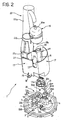
- Figure 2 is a partially exploded perspective view of the apparatus shown in Figure 1;
- Figure 3 is a partial perspective view of the apparatus of the preceding Figures and shows the relative arrangement of various devices of which it is composed;
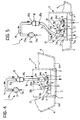
- Figures 4 and 5 are schematic representations which show the fuel supply apparatus according to the invention in two different configurations for use in a fuel supply system of the type with and without return flow.
- In the drawings the apparatus for supply of fuel to an internal combustion engine (not illustrated) is generally indicated 1.
- The apparatus 1 comprises a
closure element 2 essentially in the form of a flanged plug, intended to be fixed in a liquid-tight manner in an aperture 3 (Figures 4 and 5) formed in alower wall 4a of afuel tank 4. As better seen in Figures 2 and 3, two mushroomshape retainer members 5 are formed in the face of the closure element intended to face into the tank. - From the same face of the
closure element 2 projects a hollow tubular formation 6 in the top of which is formed a passage 7 (Figures 2, 4 and 5) . Upwardly from the top of the formation 6 adjacent thisaperture 7 project twoprojections 8. - A further hollow tubular formation 9 extends in a similar manner from the
closure element 2 towards the interior of the tank 4 (see Figures 2, 4 and 5) and itsdistal portion 9a is upwardly closed and shaped in the form of an hydraulic connector. - A multi-pole electric connector 10 (Figure 3) is sealingly engaged in an aperture 11 (Figure 2) formed in the
closure element 2. - The apparatus 1 further comprises an
electric pump 13 with alower suction connector 13a, and anupper delivery connector 13b (Figure 2). One end of atube 14 is engaged on thisdelivery connector 13b, the other end of which is connected to theinlet connector 15a of afilter 15. This filter has anoutlet connector 15b (Figure 2) engaged in aconnector tube 16. - A support structure essentially constituted by a substantially annular wall is generally indicated 17. Close to its lower end the
support structure 17 has a pair of ears 18 (of which only one is visible in Figures 1 and 2) provided with respective apertures 19 (Figure 2) into which theretainer members 5 of theclosure element 2 can be engaged. - Together with the
closure element 2 the structure orwall 17 forms a settling chamber within thefuel tank 4. - An hydraulic pressure regulator device is generally indicated 20 in the drawings. In the illustrated embodiment this device comprises a connection and support
housing 20a into which a pressure regulator indicated 20b is fitted. - In the exemplary embodiment illustrated the connection and
support housing 20a has anupper inlet connector 20c (Figures 2, 4 and 5) preferably formed blind or closed. Thehousing 20a further has a lower inlet/outlet connector 20d which can be sealingly coupled with the passage or opening 7 of thelower closure element 2. In thehousing 20a, between theconnectors tubular portion 20e of the same housing, which terminates with aflange 20f. Thetubular portion 20e has at least one longitudinal lower slot 20g. - The
pressure regulator 20b has aninlet 20h and anoutlet connector 20i essentially at 90° to one another. Thispressure regulator 20b is fitted in thetubular portion 20e of thehousing 20a and has anannular flange 201 which contacts theflange 20f of this tubular portion. Theinlet' 20h of theregulator 20b extends into the'tubular portion 20e of theholder 20a, whilst the outlet connector .20i extends downwardly through the slot 20g of this housing. - The
housing 20a further has twolateral projections 20m (Figures 2 and 3) having respective cut-out portions which can engage with, interference on theprotuberances 8 of the formation 6 of theclosure element 2. - The fuel supply apparatus 1 further comprises a Venturi
tube device 21 intended to be coupled to theoutlet connector 20i of thepressure regulator 20b. - A fuel level detector device for detecting the level.of fuel in the tank is generally indicated 22 in Figures 1 and 2. The device, of type known per se, is in particular intended to provide electrical signals indicative of the fuel level, between a predetermined maximum level and a predetermined minimum level (or reserve level).
- The
level detector 22 has an essentiallycylindrical body 22a fitted in asupport housing 22b of substantially tubular shape. - The support wall or
structure 17 has a cut-out 23 which extends downwardly from its upper edge. From the inner surface of thiswall 17 adjacent to the vertical sides of the cut-out 23 extend twoguides 24 which can receive and retain in mutual engagement theend flanges 20f and 20l, respectively, of the connection and supporthousing 20a and thepressure regulator 20b as seen in particular in Figure 1. - The
support structure 17 further has an arcuate wall portion 25 (Figures 1 and 2) internally provided withresilient retainer projections 26 able to clamp and retain theelectric pump 13. - The support housing 22b of the fuel
level detector device 22 has alower tab 22c (Figure 2) engagable in acorresponding seat 27 provided adjacent the upper edge of the support wall or structure 17 (Figure 2). - The apparatus described above can be arranged in a first or a second configuration, for use in a fuel supply system of the type with and, respectively, without return flow.
- These configurations are schematically illustrated in Figure 4 and 5.
- The configuration shown in Figure 4 relates to, use of the apparatus 1 in a fuel supply system of the type without return flow.
- In this configuration the
outlet 15b from thefilter 15 is connected, via thetube 16, to theinlet connector 20c (preliminary opened) of thepressure regulator 20. In operation in this configuration thepump 13 supplies fuel towards thetube 14, thefilter 15, thetube 16, thepressure regulator 20 and this flow of fuel through thepassage 7 of the closure element 2 (via a tube not illustrated) is adapted to the requirements of the internal combustion engine. The fuel which may be in excess is recirculated to the interior of thetank 4 through thepressure regulator 20b and in particular through itsoutlet connector 20i and the Venturiduct device 21. - In the configuration shown in Figure 4 the connector or
passage 9a of theclosure element 2 is closed. - The configuration shown in Figure 5 is, on the other hand, envisaged for use in a fuel supply system of the type having return flow. In this configuration the
outlet 15b of thefilter 15 via thetube 16 is connected to the passage orconnector 9a (preliminary opened) of theclosure element 2 in order to deliver fuel to the internal combustion engine through this connector. Theelectric connector 20c of thepressure regulator 20 is on the other hand left closed in such a way that the said pressure regulator is able to receive and to re-emit into the settling chamber 17 a flow of excess fuel which returns from the internal combustion engine through theaperture 7 of the lower closure element and the inlet/outlet connector 20d of the pressure regulator. This flow of returning fuel passes through thepressure regulator 20b and is reintroduced into the settling chamber through theoutlet connector 20i of this pressure regulator, and the associated Venturiduct device 21. - As anticipated above, the fuel supply apparatus according to the invention can, with simple and rapid operations, be set in one or the other configuration of use depending on whether it is intended to be used in a fuel supply system of the type with or without return flow.
- Naturally, the principle of the invention remaining the same, the embodiments and the details of construction can be widely varied with respect to what has been described and illustrated purely by way of non-limitative example, without by this departing from the ambit of the invention as defined in the annexed claims.
Claims (7)
- Apparatus (1) for the supply of fuel to an internal combustion engine, particularly for a motor vehicle, comprising
a closure element (2) intended for liquid-tight connection to the aperture (3) of a wall (4a) of a fuel tank (4) and in which are formed a first and a second passage (7; 9, 9a),
a support structure (17) intended to be fixed on the said closure element (2) within the tank (4);
a pump (13) carried by the said structure (17) and the delivery (13b) of which is connected to a filter (15);
a pressure regulator device (20) likewise carried by the said structure (17) and having an inlet connector (20c), an inlet/outlet connector (20d) connected to the first passage (7) of the closure element (2) and an outlet (20i) ;
the apparatus being such that the apparatus (1) can be arranged in a first or in a second configuration for use in a fuel supply system of the type with or without return flow respectively;
in the first configuration the output of the filter (15) being connected with the second passage (9, 9a) of the closure element (2) for the delivery of fuel to the engine through the said second passage (9, 9a); the inlet connector (20c) of the pressure regulator (20) being closed, in such a way that the said pressure regulator (20) is able to receive a return flow of fuel from the engine;
in the second configuration the second passage (9, 9a) of the closure element (2).being closed and the filter output (15) being connected to the inlet connector (20c) of the pressure regulator (20) to supply fuel to the engine through the said first passage (7) of the closure element (2). - Apparatus according to Claim 1, in which the second passage (9, 9a) of the closure element (2) and the inlet connector (20c) of the pressure regulator (20) are selectively openable, for the achievement of the said first and the said second configuration of use respectively.
- Apparatus according to any preceding claim, in which the support structure (17) is able to define, together with the said closure element (2), a settlement chamber within the tank (4).
- Apparatus according to any preceding claim, in which the said pressure regulator device (20) is anchored to the closure element (2) along a first direction, and is lodged.in the said support structure (17) in a manner restrained along another direction forming an angle with the said first direction.
- Apparatus according to any preceding claim, further comprising a device for detecting the level of fuel in the tank fixed to the upper portion of the said support structure (17).
- Apparatus according to Claim 3, in which the wall (17) of the said settlement chamber is provided externally with at least one resilient retainer projection (26) operable to grip and retain the pump (13).
- Apparatus according to any preceding claim, in which a Venturi tube device (21) is coupled to the outlet (20i) of the pressure regulator (20).
Applications Claiming Priority (3)
| Application Number | Priority Date | Filing Date | Title |
|---|---|---|---|
| IT2000TO000678A IT1320525B1 (en) | 2000-07-05 | 2000-07-05 | APPLIANCE FOR FUEL SUPPLY TO AN INTERNAL COMBUSTION ENGINE, PARTICULARLY FOR MOTOR VEHICLES. |
| ITTO000678 | 2000-07-05 | ||
| PCT/IB2001/001258 WO2002002925A1 (en) | 2000-07-05 | 2001-07-03 | Apparatus for the supply of fuel to an internal combustion engine, particularly for motor vehicles |
Publications (2)
| Publication Number | Publication Date |
|---|---|
| EP1299636A1 EP1299636A1 (en) | 2003-04-09 |
| EP1299636B1 true EP1299636B1 (en) | 2006-05-17 |
Family
ID=11457896
Family Applications (1)
| Application Number | Title | Priority Date | Filing Date |
|---|---|---|---|
| EP01947728A Expired - Lifetime EP1299636B1 (en) | 2000-07-05 | 2001-07-03 | Apparatus for the supply of fuel to an internal combustion engine, particularly for motor vehicles |
Country Status (7)
| Country | Link |
|---|---|
| EP (1) | EP1299636B1 (en) |
| AT (1) | ATE326629T1 (en) |
| AU (1) | AU2001269368A1 (en) |
| DE (1) | DE60119736T2 (en) |
| ES (1) | ES2259664T3 (en) |
| IT (1) | IT1320525B1 (en) |
| WO (1) | WO2002002925A1 (en) |
Families Citing this family (1)
| Publication number | Priority date | Publication date | Assignee | Title |
|---|---|---|---|---|
| US20080087349A1 (en) * | 2006-09-21 | 2008-04-17 | Siemens Vdo Automotive Corporation | Molded tube for vehicle fuel delivery module |
Family Cites Families (5)
| Publication number | Priority date | Publication date | Assignee | Title |
|---|---|---|---|---|
| JP3167104B2 (en) * | 1996-02-15 | 2001-05-21 | 株式会社ユニシアジェックス | Fuel supply unit |
| JP4417440B2 (en) * | 1996-02-16 | 2010-02-17 | 大日本印刷株式会社 | Diffusion hologram touch panel |
| FR2768667B1 (en) * | 1997-09-23 | 1999-12-03 | Bitron France | PUMPING DEVICE AND FUEL TANK FOR A MOTOR VEHICLE EQUIPPED WITH SUCH A DEVICE |
| WO1999025975A1 (en) * | 1997-11-19 | 1999-05-27 | Mitsubishi Denki Kabushiki Kaisha | Fuel feeder for vehicles |
| DE19832842C1 (en) * | 1998-07-21 | 2000-02-17 | Bosch Gmbh Robert | Fuel delivery system for supplying fuel to an internal combustion engine |
-
2000
- 2000-07-05 IT IT2000TO000678A patent/IT1320525B1/en active
-
2001
- 2001-07-03 AU AU2001269368A patent/AU2001269368A1/en not_active Abandoned
- 2001-07-03 ES ES01947728T patent/ES2259664T3/en not_active Expired - Lifetime
- 2001-07-03 AT AT01947728T patent/ATE326629T1/en not_active IP Right Cessation
- 2001-07-03 EP EP01947728A patent/EP1299636B1/en not_active Expired - Lifetime
- 2001-07-03 DE DE60119736T patent/DE60119736T2/en not_active Expired - Lifetime
- 2001-07-03 WO PCT/IB2001/001258 patent/WO2002002925A1/en not_active Ceased
Also Published As
| Publication number | Publication date |
|---|---|
| IT1320525B1 (en) | 2003-12-10 |
| ES2259664T3 (en) | 2006-10-16 |
| EP1299636A1 (en) | 2003-04-09 |
| DE60119736T2 (en) | 2006-11-23 |
| ATE326629T1 (en) | 2006-06-15 |
| DE60119736D1 (en) | 2006-06-22 |
| AU2001269368A1 (en) | 2002-01-14 |
| WO2002002925A1 (en) | 2002-01-10 |
| ITTO20000678A0 (en) | 2000-07-05 |
| ITTO20000678A1 (en) | 2002-01-05 |
Similar Documents
| Publication | Publication Date | Title |
|---|---|---|
| KR101291458B1 (en) | Filter device | |
| US5133324A (en) | Ejector pump for vehicle fuel tank | |
| US6170516B1 (en) | Solenoid valve fixing structure | |
| US20020088439A1 (en) | Fuel tank | |
| US20020083983A1 (en) | Dual barrel jet fuel pump assembly for a fuel tank | |
| US20110100985A1 (en) | Insert element for a container suitable for filling with urea at a filling station | |
| EP0773128A3 (en) | Vehicle refueling valve | |
| CN115667786A (en) | Multifunctional valve for fuel cell vehicle system | |
| KR20010020304A (en) | Fuel delivery device | |
| JP6547678B2 (en) | Vehicle side connector | |
| US10906391B2 (en) | Fuel tank having inlet check valve | |
| US4836402A (en) | Fuel tank vent system for automotive vehicles | |
| WO2002002925A1 (en) | Apparatus for the supply of fuel to an internal combustion engine, particularly for motor vehicles | |
| CN214589428U (en) | Wire harness fixing device for automobile | |
| IT8203481A1 (en) | AUTOMATIC FILLING DEVICE FOR BATTERY ELEMENTS | |
| JP2004324611A (en) | Reserve vessel unit and jet pump | |
| JP2006029187A (en) | Fuel tank lid | |
| JP4370528B2 (en) | Fuel supply device | |
| JPS63192999A (en) | Ejector pump of fuel tank device for vehicle | |
| CN212564935U (en) | Anti-disassembly buckle for water pipe joint | |
| EP1160445A2 (en) | "Fuel supplying apparatus" | |
| CN213429664U (en) | Mounting structure of water dispenser filter element and water tank | |
| CN222346953U (en) | Water splashing prevention device for wire harness connector of vehicle controller and vehicle | |
| CN217381884U (en) | Sealing structure of display panel and faucet | |
| KR100471310B1 (en) | Fuel tank with one-way valve |
Legal Events
| Date | Code | Title | Description |
|---|---|---|---|
| PUAI | Public reference made under article 153(3) epc to a published international application that has entered the european phase |
Free format text: ORIGINAL CODE: 0009012 |
|
| AK | Designated contracting states |
Kind code of ref document: A1 Designated state(s): AT BE CH CY DE DK ES FI FR GB GR IE IT LI LU MC NL PT SE TR |
|
| AX | Request for extension of the european patent |
Extension state: AL LT LV MK RO SI |
|
| 17P | Request for examination filed |
Effective date: 20030203 |
|
| GRAP | Despatch of communication of intention to grant a patent |
Free format text: ORIGINAL CODE: EPIDOSNIGR1 |
|
| RIN1 | Information on inventor provided before grant (corrected) |
Inventor name: CECCHELLI, IVAN |
|
| RAP1 | Party data changed (applicant data changed or rights of an application transferred) |
Owner name: BITRON S.P.A. |
|
| GRAS | Grant fee paid |
Free format text: ORIGINAL CODE: EPIDOSNIGR3 |
|
| GRAA | (expected) grant |
Free format text: ORIGINAL CODE: 0009210 |
|
| AK | Designated contracting states |
Kind code of ref document: B1 Designated state(s): AT BE CH CY DE DK ES FI FR GB GR IE IT LI LU MC NL PT SE TR |
|
| PG25 | Lapsed in a contracting state [announced via postgrant information from national office to epo] |
Ref country code: FI Free format text: LAPSE BECAUSE OF FAILURE TO SUBMIT A TRANSLATION OF THE DESCRIPTION OR TO PAY THE FEE WITHIN THE PRESCRIBED TIME-LIMIT Effective date: 20060517 Ref country code: LI Free format text: LAPSE BECAUSE OF FAILURE TO SUBMIT A TRANSLATION OF THE DESCRIPTION OR TO PAY THE FEE WITHIN THE PRESCRIBED TIME-LIMIT Effective date: 20060517 Ref country code: BE Free format text: LAPSE BECAUSE OF FAILURE TO SUBMIT A TRANSLATION OF THE DESCRIPTION OR TO PAY THE FEE WITHIN THE PRESCRIBED TIME-LIMIT Effective date: 20060517 Ref country code: CH Free format text: LAPSE BECAUSE OF FAILURE TO SUBMIT A TRANSLATION OF THE DESCRIPTION OR TO PAY THE FEE WITHIN THE PRESCRIBED TIME-LIMIT Effective date: 20060517 Ref country code: NL Free format text: LAPSE BECAUSE OF FAILURE TO SUBMIT A TRANSLATION OF THE DESCRIPTION OR TO PAY THE FEE WITHIN THE PRESCRIBED TIME-LIMIT Effective date: 20060517 |
|
| REG | Reference to a national code |
Ref country code: GB Ref legal event code: FG4D |
|
| REG | Reference to a national code |
Ref country code: CH Ref legal event code: EP |
|
| REG | Reference to a national code |
Ref country code: IE Ref legal event code: FG4D |
|
| REF | Corresponds to: |
Ref document number: 60119736 Country of ref document: DE Date of ref document: 20060622 Kind code of ref document: P |
|
| PG25 | Lapsed in a contracting state [announced via postgrant information from national office to epo] |
Ref country code: IE Free format text: LAPSE BECAUSE OF NON-PAYMENT OF DUE FEES Effective date: 20060703 |
|
| PG25 | Lapsed in a contracting state [announced via postgrant information from national office to epo] |
Ref country code: MC Free format text: LAPSE BECAUSE OF NON-PAYMENT OF DUE FEES Effective date: 20060731 |
|
| PG25 | Lapsed in a contracting state [announced via postgrant information from national office to epo] |
Ref country code: DK Free format text: LAPSE BECAUSE OF FAILURE TO SUBMIT A TRANSLATION OF THE DESCRIPTION OR TO PAY THE FEE WITHIN THE PRESCRIBED TIME-LIMIT Effective date: 20060817 |
|
| REG | Reference to a national code |
Ref country code: SE Ref legal event code: TRGR |
|
| REG | Reference to a national code |
Ref country code: ES Ref legal event code: FG2A Ref document number: 2259664 Country of ref document: ES Kind code of ref document: T3 |
|
| PG25 | Lapsed in a contracting state [announced via postgrant information from national office to epo] |
Ref country code: PT Free format text: LAPSE BECAUSE OF FAILURE TO SUBMIT A TRANSLATION OF THE DESCRIPTION OR TO PAY THE FEE WITHIN THE PRESCRIBED TIME-LIMIT Effective date: 20061017 |
|
| NLV1 | Nl: lapsed or annulled due to failure to fulfill the requirements of art. 29p and 29m of the patents act | ||
| ET | Fr: translation filed | ||
| REG | Reference to a national code |
Ref country code: CH Ref legal event code: PL |
|
| PLBE | No opposition filed within time limit |
Free format text: ORIGINAL CODE: 0009261 |
|
| STAA | Information on the status of an ep patent application or granted ep patent |
Free format text: STATUS: NO OPPOSITION FILED WITHIN TIME LIMIT |
|
| 26N | No opposition filed |
Effective date: 20070220 |
|
| PG25 | Lapsed in a contracting state [announced via postgrant information from national office to epo] |
Ref country code: GR Free format text: LAPSE BECAUSE OF FAILURE TO SUBMIT A TRANSLATION OF THE DESCRIPTION OR TO PAY THE FEE WITHIN THE PRESCRIBED TIME-LIMIT Effective date: 20060818 |
|
| PG25 | Lapsed in a contracting state [announced via postgrant information from national office to epo] |
Ref country code: LU Free format text: LAPSE BECAUSE OF NON-PAYMENT OF DUE FEES Effective date: 20060703 Ref country code: TR Free format text: LAPSE BECAUSE OF FAILURE TO SUBMIT A TRANSLATION OF THE DESCRIPTION OR TO PAY THE FEE WITHIN THE PRESCRIBED TIME-LIMIT Effective date: 20060517 |
|
| PG25 | Lapsed in a contracting state [announced via postgrant information from national office to epo] |
Ref country code: CY Free format text: LAPSE BECAUSE OF FAILURE TO SUBMIT A TRANSLATION OF THE DESCRIPTION OR TO PAY THE FEE WITHIN THE PRESCRIBED TIME-LIMIT Effective date: 20060517 |
|
| PGFP | Annual fee paid to national office [announced via postgrant information from national office to epo] |
Ref country code: AT Payment date: 20090715 Year of fee payment: 9 Ref country code: SE Payment date: 20090730 Year of fee payment: 9 |
|
| PGFP | Annual fee paid to national office [announced via postgrant information from national office to epo] |
Ref country code: DE Payment date: 20100723 Year of fee payment: 10 |
|
| PG25 | Lapsed in a contracting state [announced via postgrant information from national office to epo] |
Ref country code: AT Free format text: LAPSE BECAUSE OF NON-PAYMENT OF DUE FEES Effective date: 20100703 |
|
| PGFP | Annual fee paid to national office [announced via postgrant information from national office to epo] |
Ref country code: GB Payment date: 20110721 Year of fee payment: 11 Ref country code: FR Payment date: 20110810 Year of fee payment: 11 Ref country code: ES Payment date: 20110713 Year of fee payment: 11 |
|
| PGFP | Annual fee paid to national office [announced via postgrant information from national office to epo] |
Ref country code: IT Payment date: 20110718 Year of fee payment: 11 |
|
| PG25 | Lapsed in a contracting state [announced via postgrant information from national office to epo] |
Ref country code: SE Free format text: LAPSE BECAUSE OF NON-PAYMENT OF DUE FEES Effective date: 20100704 |
|
| GBPC | Gb: european patent ceased through non-payment of renewal fee |
Effective date: 20120703 |
|
| REG | Reference to a national code |
Ref country code: FR Ref legal event code: ST Effective date: 20130329 |
|
| PG25 | Lapsed in a contracting state [announced via postgrant information from national office to epo] |
Ref country code: FR Free format text: LAPSE BECAUSE OF NON-PAYMENT OF DUE FEES Effective date: 20120731 Ref country code: DE Free format text: LAPSE BECAUSE OF NON-PAYMENT OF DUE FEES Effective date: 20130201 Ref country code: GB Free format text: LAPSE BECAUSE OF NON-PAYMENT OF DUE FEES Effective date: 20120703 |
|
| PG25 | Lapsed in a contracting state [announced via postgrant information from national office to epo] |
Ref country code: IT Free format text: LAPSE BECAUSE OF NON-PAYMENT OF DUE FEES Effective date: 20120703 |
|
| REG | Reference to a national code |
Ref country code: DE Ref legal event code: R119 Ref document number: 60119736 Country of ref document: DE Effective date: 20130201 |
|
| REG | Reference to a national code |
Ref country code: ES Ref legal event code: FD2A Effective date: 20131018 |
|
| PG25 | Lapsed in a contracting state [announced via postgrant information from national office to epo] |
Ref country code: ES Free format text: LAPSE BECAUSE OF NON-PAYMENT OF DUE FEES Effective date: 20120704 |