EP1298956A1 - Système optique directionnel re-configurable - Google Patents
Système optique directionnel re-configurable Download PDFInfo
- Publication number
- EP1298956A1 EP1298956A1 EP02292300A EP02292300A EP1298956A1 EP 1298956 A1 EP1298956 A1 EP 1298956A1 EP 02292300 A EP02292300 A EP 02292300A EP 02292300 A EP02292300 A EP 02292300A EP 1298956 A1 EP1298956 A1 EP 1298956A1
- Authority
- EP
- European Patent Office
- Prior art keywords
- optical
- switches
- cables
- optical device
- outputs
- Prior art date
- Legal status (The legal status is an assumption and is not a legal conclusion. Google has not performed a legal analysis and makes no representation as to the accuracy of the status listed.)
- Withdrawn
Links
- 230000003287 optical effect Effects 0.000 title claims abstract description 83
- 238000000605 extraction Methods 0.000 claims description 3
- 238000003780 insertion Methods 0.000 claims description 3
- 230000037431 insertion Effects 0.000 claims description 3
- 239000011159 matrix material Substances 0.000 claims description 2
- 239000000835 fiber Substances 0.000 description 24
- 239000013307 optical fiber Substances 0.000 description 6
- 238000004891 communication Methods 0.000 description 4
- 235000021183 entrée Nutrition 0.000 description 4
- 230000000644 propagated effect Effects 0.000 description 2
- 229910052691 Erbium Inorganic materials 0.000 description 1
- 230000005540 biological transmission Effects 0.000 description 1
- 238000005516 engineering process Methods 0.000 description 1
- UYAHIZSMUZPPFV-UHFFFAOYSA-N erbium Chemical compound [Er] UYAHIZSMUZPPFV-UHFFFAOYSA-N 0.000 description 1
- 238000000034 method Methods 0.000 description 1
Images


Classifications
-
- H—ELECTRICITY
- H04—ELECTRIC COMMUNICATION TECHNIQUE
- H04Q—SELECTING
- H04Q11/00—Selecting arrangements for multiplex systems
- H04Q11/0001—Selecting arrangements for multiplex systems using optical switching
- H04Q11/0003—Details
-
- H—ELECTRICITY
- H04—ELECTRIC COMMUNICATION TECHNIQUE
- H04J—MULTIPLEX COMMUNICATION
- H04J14/00—Optical multiplex systems
- H04J14/02—Wavelength-division multiplex systems
- H04J14/0201—Add-and-drop multiplexing
- H04J14/0202—Arrangements therefor
- H04J14/021—Reconfigurable arrangements, e.g. reconfigurable optical add/drop multiplexers [ROADM] or tunable optical add/drop multiplexers [TOADM]
- H04J14/0212—Reconfigurable arrangements, e.g. reconfigurable optical add/drop multiplexers [ROADM] or tunable optical add/drop multiplexers [TOADM] using optical switches or wavelength selective switches [WSS]
-
- H—ELECTRICITY
- H04—ELECTRIC COMMUNICATION TECHNIQUE
- H04J—MULTIPLEX COMMUNICATION
- H04J14/00—Optical multiplex systems
- H04J14/02—Wavelength-division multiplex systems
- H04J14/0201—Add-and-drop multiplexing
- H04J14/0215—Architecture aspects
- H04J14/0217—Multi-degree architectures, e.g. having a connection degree greater than two
-
- H—ELECTRICITY
- H04—ELECTRIC COMMUNICATION TECHNIQUE
- H04Q—SELECTING
- H04Q11/00—Selecting arrangements for multiplex systems
- H04Q11/0001—Selecting arrangements for multiplex systems using optical switching
- H04Q11/0005—Switch and router aspects
-
- H—ELECTRICITY
- H04—ELECTRIC COMMUNICATION TECHNIQUE
- H04Q—SELECTING
- H04Q11/00—Selecting arrangements for multiplex systems
- H04Q11/0001—Selecting arrangements for multiplex systems using optical switching
- H04Q11/0005—Switch and router aspects
- H04Q2011/0007—Construction
- H04Q2011/0024—Construction using space switching
-
- H—ELECTRICITY
- H04—ELECTRIC COMMUNICATION TECHNIQUE
- H04Q—SELECTING
- H04Q11/00—Selecting arrangements for multiplex systems
- H04Q11/0001—Selecting arrangements for multiplex systems using optical switching
- H04Q11/0005—Switch and router aspects
- H04Q2011/0052—Interconnection of switches
-
- H—ELECTRICITY
- H04—ELECTRIC COMMUNICATION TECHNIQUE
- H04Q—SELECTING
- H04Q11/00—Selecting arrangements for multiplex systems
- H04Q11/0001—Selecting arrangements for multiplex systems using optical switching
- H04Q11/0062—Network aspects
- H04Q2011/0079—Operation or maintenance aspects
- H04Q2011/0081—Fault tolerance; Redundancy; Recovery; Reconfigurability
-
- H—ELECTRICITY
- H04—ELECTRIC COMMUNICATION TECHNIQUE
- H04Q—SELECTING
- H04Q11/00—Selecting arrangements for multiplex systems
- H04Q11/0001—Selecting arrangements for multiplex systems using optical switching
- H04Q11/0062—Network aspects
- H04Q2011/0086—Network resource allocation, dimensioning or optimisation
Definitions
- the present invention relates to the technology of fiber optic transmissions in general, and describes more particularly a directional optical system reconfigurable.
- optical fibers for the realization of new communication networks has become the rule.
- These cables are used to interconnect optical communication equipment, by example an optical interconnection system or OXC (100) for 'Optical Cross-Connect', to distribute traffic flowing between the fibers of the three cables (110, 112, 114) in this particular example of Figure 1A.
- OXC optical interconnection system
- Figure 1B shows an often necessary device which is a optical insertion and extraction multiplexer local or OADM (130) for 'Optical Add / Drop Multiplexer'.
- OADM optical insertion and extraction multiplexer local or OADM (130) for 'Optical Add / Drop Multiplexer'.
- the part of incoming traffic on one or more fibers (132), and which is intended for local use, is derived by the OADM device which must also insert the locally generated traffic (136). So the outgoing traffic on one or more fibers (138) includes all incoming traffic (132) less locally derived traffic (134) plus traffic locally generated (136).
- FIG. 1C Another type of device used in networks optical, shown in Figure 1C, is an amplifier of light (140) often of the EDFA type for 'Erbium Doped optical Fiber Amplifier 'which is used to amplify the signal level incoming light (142). When these need to be propagated over long distances, the amplifier outputs (144) a level sufficient for their local treatment or as relay to an even more distant destination.
- FIG. 1A the four fibers of the cable on the left of figure (114) propagate the light signals for two fibers to the right and for the other two fibers to left.
- the situation is similar for other cables (110, 112).
- So fiber resources are allocated in a fixed way with the consequence that the resources in a direction should be assigned for the traffic peak at bear in this direction.
- specialists in communications networks are well aware that, on the one hand, the traffic at a network node can be very asymmetrical, a direction to be able to support the transportation of a lot more information than the other.
- the object of the invention is to provide a directional optical system which is reconfigurable so allow the allocation of fiber optic resources of a network in a dynamic way.
- the system according to the invention makes it possible to change the direction of propagation of light signals in a fiber network optics to avoid having to size it according to the peak traffic to bear, in both directions, between two nodes of the network.
- FIG. 2 shows a set of cables (200) of optical fibers whose direction of propagation of each of the individual fibers, for example (210), is not assigned by a in a fixed manner unlike the prior art previously discussed with Figures 1A to 1C.
- the optical fibers must access a device (230) formed of several sub-devices D1, D2, D3 for processing the optical signals which they transport.
- These devices are, among others, of the type of those shown in FIGS. 1A to 1C, ie OXC, OADM and optical amplifier.
- the above list is not exhaustive and only includes conventional optical devices which may be affected by the invention.
- NxN optical switch that is to say capable of optically connecting any of the N upper inputs / outputs (270) with n ' any of the N lower inputs / outputs (210).
- N corresponds to the total of the inputs and outputs of the optical devices (230), the number of 16 in this particular example, divided into 7 outputs (240) and 9 inputs (250) connected to the upper inputs / outputs ( 270) of the optical switch (260).
- the various optical devices (230) are available to process the information which must circulate on all of the cables (200) thus grouping together at least N fibers, 16 fibers in this example being connected to the lower inputs / outputs (210) of the optical switch.
- the optical fibers can be distributed individually to make the best use of the optical devices according to the traffic to be transported at a given time.
- Figure 2 is of course only a particular example of use of the optical switch (260).
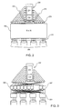
- FIG. 3 is an example of a more specific implementation of the invention using optical switches of smaller dimensions, therefore not individually having the twice N necessary inputs / outputs.
- the switch (260) of Figure 2 can therefore in practice be implemented, for example, from two groups of smaller switches.
- a first group consists of four 4x9 switches (224) constituting a first switching layer supplying a second layer comprising 4x2 (228) and 4x1 (227) switches, it being understood that the latter can be, in practice, 4x2 of which only uses one output.
- the same functionality is thus obtained as that of FIG. 2 with, however, small switches.
- the first layer of switches associates a switch with each cable, thus authorizing the switching of any fiber of a cable to any switch of the second layer.
- the latter combines a switch by input / output pair of the directional device (230). If there are more inputs than outputs, as is the case in the example of figure 3 where there are 9 inputs for 7 outputs, the second layer must also associate a switch (227) by additional entry, two in this example. The reverse is also true. If the directional device (230) has more outputs than inputs, a switch must be associated with each additional output. Thus, each of these switches of the second layer makes it possible to connect an input and an output separately to two separate cables through the switches of the first layer.
- FIG. 4A shows a series (300, 310 and 320) of optical insertion and extraction multiplexers (OADM) such as can be found in successive nodes, for example, of a ring network.
- OADM optical insertion and extraction multiplexers
- optical devices are OADMs or similar devices, example for which each 2x2 switch is connected on one side directly to an input and an output of the optical devices (320), and on the other side to each of the two cables, for one directly, and for the other through a 4x4 switching matrix (340).
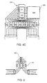
- FIG. 4B illustrates the example of an 8 ⁇ 8 switch (360) placed in front of the eight inputs of an optical device (370) of the type of those of FIG. 4A while two cables of eight fibers each are connected to eight optical switches 2x2 similar to those in Figure 4A.
- a 16x16 switch should normally have been used.
- FIG. 4B it is simply a different positioning of the switch (360). While in Figure 4A, the switch (340) is placed before the 2x2 switches (350) it is, in Figure 4B, between the 2x2 switches and the optical devices (370).
- Figure 4C shows another possible positioning of the 8x8 switch (360) in the previous figure, the switch being placed here at the output of the optical devices (370).
- FIG. 5 shows another embodiment of the invention which provides an even greater simplification in the case of devices of the optical amplifier type (400).
- the accesses are divided into two cables and only 2x2 optical switches (410) are necessary to be able to use the fibers, and the amplifiers, in one or the other direction.
- each of the 2x2 switches is connected directly to an input and an output of the amplifier.
- Figure 3 Figures 4A, 4B and 4C as well as Figure 5 are intended to show that the implementation of the invention can take many forms with benefits particular depending on the optical devices used and fiber optic cable configurations you need interconnect. Those skilled in the art will appreciate the benefits that there would be to use, in a particular context, one either of these forms when making the invention.
Landscapes
- Engineering & Computer Science (AREA)
- Computer Networks & Wireless Communication (AREA)
- Signal Processing (AREA)
- Optical Communication System (AREA)
- Use Of Switch Circuits For Exchanges And Methods Of Control Of Multiplex Exchanges (AREA)
Abstract
Description
- au moins un dispositif optique ayant des entrées et des sorties unidirectionnelles dont le nombre total est égal ou inférieur à N, et
- un commutateur optique NxN adapté pour que chacun desdits accès puisse être couplé indifféremment soit à une desdites entrées, soit à une desdites sorties dudit dispositif optique ; ledit commutateur optique NxN étant réalisé à partir d'une combinaison de commutateurs optiques nxp de plus petite taille, et où n et p sont inférieurs à N ;
Claims (10)
- Système optique directionnel re-configurable comprenant N accès (210) répartis en une pluralité de câbles (200), chaque accès pouvant être configuré individuellement en tant qu'entrée ou sortie ; ledit système comprenant :caractérisé en ce que le nombre de commutateurs de petite taille (224) de ladite première couche de commutation est égal au nombre desdits câbles, et le nombre de commutateurs de petite taille (227, 228) de ladite seconde couche de commutation est égal au nombre le plus élevé entre le nombre d'entrées et le nombre de sorties dudit dispositif optique (230) de sorte qu'une entrée et une sortie dudit dispositif optique puissent être connectées à deux câbles distincts parmi ladite pluralité de câbles.au moins un dispositif optique (230) ayant des entrées (250) et des sorties (240) unidirectionnelles dont le nombre total est égal ou inférieur à N, etun commutateur optique NxN (260) adapté pour que chacun desdits accès (210) puisse être couplé indifféremment soit à une desdites entrées (250), soit à une desdites sorties (240) dudit dispositif optique (230) ; ledit commutateur optique NxN comprenant une première et une seconde couche de commutation, réalisées à partir de commutateurs optiques nxp de plus petite taille (224, 227 et 228), et où n et p sont inférieurs à N ;
- Système selon la revendication 1, caractérisé en ce que ladite première couche de commutation comporte une pluralité de commutateurs de petite taille (224) connectés directement auxdits accès, et ladite seconde couche de commutation comporte une pluralité de commutateurs de petite taille (227, 228) connectés directement aux entrées et sorties dudit dispositif optique (230), lesdites plusieurs couches de commutation réalisant ensemble la fonction globale dudit commutateur optique.
- Système selon la revendication 1, caractérisé en ce que les entrées dudit dispositif optique (370) sont toutes connectées à un seul commutateur optique de plus petite taille (360), les entrées dudit commutateur optique de plus petite taille et les sorties dudit dispositif optique étant connectées à une série de commutateurs 2x2 pour assurer ensemble la fonction globale dudit commutateur optique.
- Système selon la revendication 1, caractérisé en ce que les sorties dudit dispositif optique (370) sont toutes connectées à un seul commutateur optique de plus petite taille (360), les sorties dudit commutateur optique de plus petite taille et les entrées dudit dispositif optique étant connectées à une série de commutateurs 2x2 pour assurer ensemble la fonction globale dudit commutateur optique.
- Système selon la revendication 3, caractérisé en ce que lesdits accès sont répartis en deux câbles et chacun desdits commutateurs 2x2 est connecté à chacun desdits câbles de sorte que une entrée et une sortie dudit dispositif optique (370) puissent être connectées respectivement à chacun des deux câbles.
- Système selon la revendication 1, caractérisé en ce que lesdits accès sont répartis en deux câbles (330) et ledit commutateur optique comprend une couche de commutateurs 2x2 (350), chacun desdits commutateurs 2x2 étant connecté d'un côté directement à une entrée et une sortie dudit dispositif optique (320), et de l'autre à chacun desdits câbles, directement pour l'un d'eux et par l'intermédiaire d'une matrice de commutation 4x4 (340) pour l'autre.
- Système selon la revendication 1, caractérisé en ce que ledit dispositif optique est du type amplificateur optique (400).
- Système selon la revendication 7, caractérisé en ce que lesdits accès sont répartis en deux câbles et ledit commutateur optique comprend une couche de commutateurs 2x2 (410), chacun desdits commutateurs 2x2 étant connecté à une entrée et une sortie dudit amplificateur optique (400).
- Système selon l'une des revendications 1 à 8, caractérisé en ce ledit dispositif optique (230, 370) est composé de plusieurs sous-dispositifs optiques (D1, D2, D3).
- Arrangement composé d'une pluralité de multiplexeurs d'insertion et d'extraction optique OADM (300, 310, 320) en série caractérisé en ce que chacun desdits multiplexeurs est un système selon l'une des revendications 1 à 8.
Applications Claiming Priority (2)
| Application Number | Priority Date | Filing Date | Title |
|---|---|---|---|
| FR0112596A FR2830333B1 (fr) | 2001-10-01 | 2001-10-01 | Systeme optique directionnel re-configurable |
| FR0112596 | 2001-10-01 |
Publications (1)
| Publication Number | Publication Date |
|---|---|
| EP1298956A1 true EP1298956A1 (fr) | 2003-04-02 |
Family
ID=8867792
Family Applications (1)
| Application Number | Title | Priority Date | Filing Date |
|---|---|---|---|
| EP02292300A Withdrawn EP1298956A1 (fr) | 2001-10-01 | 2002-09-19 | Système optique directionnel re-configurable |
Country Status (4)
| Country | Link |
|---|---|
| US (1) | US7254328B2 (fr) |
| EP (1) | EP1298956A1 (fr) |
| JP (1) | JP2003188820A (fr) |
| FR (1) | FR2830333B1 (fr) |
Citations (3)
| Publication number | Priority date | Publication date | Assignee | Title |
|---|---|---|---|---|
| EP0790724A2 (fr) * | 1996-02-13 | 1997-08-20 | Nec Corporation | Système de commutation de type ATM avec réseaux de distribution pour modèles de trafic variables |
| US5930016A (en) * | 1996-10-10 | 1999-07-27 | Tellabs Operations, Inc. | Upgradable modular wavelength division multiplexer |
| US6101016A (en) * | 1996-06-25 | 2000-08-08 | Nortel Networks Corporation | Optical transmission systems using optical amplifiers and wavelength division multiplexing |
Family Cites Families (7)
| Publication number | Priority date | Publication date | Assignee | Title |
|---|---|---|---|---|
| US5018129A (en) * | 1989-03-09 | 1991-05-21 | At&T Bell Laboratories | Dual rail dilated switching networks |
| US5181134A (en) * | 1991-03-15 | 1993-01-19 | At&T Bell Laboratories | Photonic cross-connect switch |
| DE59607789D1 (de) * | 1995-06-08 | 2001-10-31 | Siemens Ag | Blockierungsfreie multicast wdm-koppelanordnung |
| US6205158B1 (en) * | 1997-12-19 | 2001-03-20 | Nortel Networks Limited | Network architectures with transparent transport capabilities |
| WO2000041430A1 (fr) * | 1998-12-30 | 2000-07-13 | Optical Technologies U.S.A. Corp. | Commutateur brasseur a modularite de la longueur d'onde |
| FR2814902B1 (fr) * | 2000-10-02 | 2002-12-20 | Cit Alcatel | Commutateur pour reseau de transmission optique utilisant le multiplexage en longueur d'onde |
| US6574386B1 (en) * | 2001-04-20 | 2003-06-03 | Transparent Networks, Inc. | Dynamically reconfigurable optical switching system |
-
2001
- 2001-10-01 FR FR0112596A patent/FR2830333B1/fr not_active Expired - Fee Related
-
2002
- 2002-09-19 EP EP02292300A patent/EP1298956A1/fr not_active Withdrawn
- 2002-09-25 US US10/252,788 patent/US7254328B2/en not_active Expired - Fee Related
- 2002-09-30 JP JP2002286208A patent/JP2003188820A/ja active Pending
Patent Citations (3)
| Publication number | Priority date | Publication date | Assignee | Title |
|---|---|---|---|---|
| EP0790724A2 (fr) * | 1996-02-13 | 1997-08-20 | Nec Corporation | Système de commutation de type ATM avec réseaux de distribution pour modèles de trafic variables |
| US6101016A (en) * | 1996-06-25 | 2000-08-08 | Nortel Networks Corporation | Optical transmission systems using optical amplifiers and wavelength division multiplexing |
| US5930016A (en) * | 1996-10-10 | 1999-07-27 | Tellabs Operations, Inc. | Upgradable modular wavelength division multiplexer |
Also Published As
| Publication number | Publication date |
|---|---|
| JP2003188820A (ja) | 2003-07-04 |
| FR2830333B1 (fr) | 2004-04-09 |
| US20030063840A1 (en) | 2003-04-03 |
| US7254328B2 (en) | 2007-08-07 |
| FR2830333A1 (fr) | 2003-04-04 |
Similar Documents
| Publication | Publication Date | Title |
|---|---|---|
| EP2141842B1 (fr) | Dispositif de commutation de signaux optiques | |
| EP0687085B1 (fr) | Multiplexeur spectral optique à insertion-extraction | |
| EP2471274B1 (fr) | Representation des degradations physiques dans un reseau de communication optique | |
| EP0592330B1 (fr) | Réseau de transmission optique avec matrice de commutation | |
| FR2726726A1 (fr) | Systeme de commutateur pour paquets optiques | |
| Calabretta et al. | Photonic integrated WDM cross-connects for optical metro and data center networks | |
| EP0838918B1 (fr) | Dispositif d'extraction-insertion de canaux de multiplex de longueurs d'onde | |
| Way et al. | Wavelength contention-free via optical bypass within a colorless and directionless ROADM | |
| EP0543714A1 (fr) | Repartiteur optique | |
| FR2933256A1 (fr) | Dispositif de commutation de signaux optiques | |
| EP1298956A1 (fr) | Système optique directionnel re-configurable | |
| FR2789538A1 (fr) | Modules de commutation, matrice de commutation comportant de tels modules, et reseau de commutation modulaire non bloquant comportant une telle matrice | |
| EP1349417B1 (fr) | Brasseur de signaux diffusant notamment pour signaux optiques | |
| EP1235377A2 (fr) | Dispositif d'extraction de frequence | |
| EP1691569B1 (fr) | Dispositif de commutation optique semi-transparant réconfigurable | |
| FR2752119A1 (fr) | Equipement optique de connexion croisee et equipement d'addition/de supression de signaux incluant un tel equipement optique de connexion croisee | |
| EP1193995A1 (fr) | Commutateur pour réseau de transmission optique utilisant le multiplexage en longueur d'onde | |
| EP1793644B1 (fr) | Dispositif de communication optique pour un noeud transparent adapté à l'égalisation spectrale | |
| Zhao et al. | Wavelength contention resolution in WSS based ROADMs | |
| FR2937815A1 (fr) | Dispositif de commutation de signaux optiques | |
| EP1379100B1 (fr) | Brasseur optique d'architecture multigranulaire | |
| FR2527882A1 (fr) | Concentrateur numerique | |
| FR2844955A1 (fr) | Brasseur optique d'architecture multigranulaire | |
| EP1455551A2 (fr) | Module de selection pour commutateur de signaux optiques et commutateur de signaux optiques | |
| Peng et al. | Network performance simulation of novel joint multicasting capable optical cross-connect based on space-and frequency-splitters |
Legal Events
| Date | Code | Title | Description |
|---|---|---|---|
| PUAI | Public reference made under article 153(3) epc to a published international application that has entered the european phase |
Free format text: ORIGINAL CODE: 0009012 |
|
| AK | Designated contracting states |
Kind code of ref document: A1 Designated state(s): AT BE BG CH CY CZ DE DK EE ES FI FR GB GR IE IT LI LU MC NL PT SE SK TR Designated state(s): AT BE BG CH CY CZ DE DK EE ES FI FR GB GR IE IT LI LU MC NL PT SE SK TR |
|
| AX | Request for extension of the european patent |
Extension state: AL LT LV MK RO SI |
|
| 17P | Request for examination filed |
Effective date: 20031002 |
|
| AKX | Designation fees paid |
Designated state(s): AT BE BG CH CY CZ DE DK EE ES FI FR GB GR IE IT LI LU MC NL PT SE SK TR |
|
| RAP1 | Party data changed (applicant data changed or rights of an application transferred) |
Owner name: ALCATEL LUCENT |
|
| STAA | Information on the status of an ep patent application or granted ep patent |
Free format text: STATUS: THE APPLICATION IS DEEMED TO BE WITHDRAWN |
|
| 18D | Application deemed to be withdrawn |
Effective date: 20090401 |