EP1298889A2 - Portable communication apparatus and microphone device for the apparatus - Google Patents
Portable communication apparatus and microphone device for the apparatus Download PDFInfo
- Publication number
- EP1298889A2 EP1298889A2 EP02021197A EP02021197A EP1298889A2 EP 1298889 A2 EP1298889 A2 EP 1298889A2 EP 02021197 A EP02021197 A EP 02021197A EP 02021197 A EP02021197 A EP 02021197A EP 1298889 A2 EP1298889 A2 EP 1298889A2
- Authority
- EP
- European Patent Office
- Prior art keywords
- openable
- sound
- microphone
- close
- closable member
- Prior art date
- Legal status (The legal status is an assumption and is not a legal conclusion. Google has not performed a legal analysis and makes no representation as to the accuracy of the status listed.)
- Withdrawn
Links
Images





Classifications
-
- H—ELECTRICITY
- H04—ELECTRIC COMMUNICATION TECHNIQUE
- H04M—TELEPHONIC COMMUNICATION
- H04M1/00—Substation equipment, e.g. for use by subscribers
- H04M1/02—Constructional features of telephone sets
- H04M1/19—Arrangements of transmitters, receivers, or complete sets to prevent eavesdropping, to attenuate local noise or to prevent undesired transmission; Mouthpieces or receivers specially adapted therefor
-
- H—ELECTRICITY
- H04—ELECTRIC COMMUNICATION TECHNIQUE
- H04M—TELEPHONIC COMMUNICATION
- H04M1/00—Substation equipment, e.g. for use by subscribers
- H04M1/02—Constructional features of telephone sets
- H04M1/0202—Portable telephone sets, e.g. cordless phones, mobile phones or bar type handsets
- H04M1/0206—Portable telephones comprising a plurality of mechanically joined movable body parts, e.g. hinged housings
- H04M1/0208—Portable telephones comprising a plurality of mechanically joined movable body parts, e.g. hinged housings characterized by the relative motions of the body parts
- H04M1/0214—Foldable telephones, i.e. with body parts pivoting to an open position around an axis parallel to the plane they define in closed position
Definitions
- the present invention relates to a portable communication apparatus and a microphone device for the apparatus.
- an openable/closable member which incorporates a microphone is attached in an openable and closable manner to the main unit of the portable apparatus so that, in both the cases where the openable/closable member is opened, and where the member is closed, a speech quality of a very high S/N ratio can be obtained at a substantially same degree.
- Japanese Patent Application Laying-Open No. 11-32107 discloses a portable communication apparatus.
- a microphone is incorporated into a flip which is screwed in an openable and closable manner to the main unit of the apparatus, and a sound-pick up hole for enabling the microphone to pick up a sound is opened in each of inner and outer flips of the flip, so that, when the flip is closed, the microphone can pick up a sound through the sound-pick up hole of the outer flip, and, when the flip is opened, the microphone can pick up a sound through the sound-pick up hole of the inner flip.
- a cordless telephone and a portable telephone are indicated as the portable communication apparatus, and it is described that the portions where the sound-pick up holes of the outer and inner flips are opened are located in places which are close to the free end which is remote from the center position of the opening and closing movements of the flip.
- Japanese Patent Application Laying-Open No. 11-308314 discloses a telephone apparatus.
- a close-talking microphone close-talking electret condenser microphone
- a movable member which is openably and closably attached to the main unit, and the sound holes are located in places which are close to the free end of the movable member.
- the close-talking microphone functions as an omnidirectional microphone
- both the sound holes remain opened, so that the proximity effect is produced for a sound source close to one of the sound holes, to improve the speech quality.
- Japanese Patent Application Laying-Open No. 11-177664 discloses a microphone device for a portable telephone.
- an ominidirectional microphone is incorporated in a flip which covers the front face of a portable telephone in a manner similar to a folding type one, and sound holes are formed respectively in the front and back faces of a center portion in the longitudinal direction of the flip.
- both a sound wave which passes through the sound hole of the front face of the flip, and that which passes through the sound hole of the back face of the flip reach the front face of the ominidirectional microphone.
- both the sound-pick up holes which are respectively formed in the outer and inner flips constituting the flip are positioned in places which are close to the free end of the flip.
- the sound-pick up holes are configured so that, when the flip is opened, the sound-pick up hole of the inner flip is positioned in the vicinity of the mouth, for example, the sound-pick up hole of the outer flip is remote from the mouth when the flip is closed. Therefore, the difference between the sound pressure applied to the microphone in the case where the flip is opened, and that in the case where the flip is closed becomes large, thereby causing a problem in that the speech qualities in the cases are remarkably different from each other.
- the telephone apparatus of the second prior art example is configured so that, only when the movable member is opened, the close-talking microphone exerts the proximity effect, and, when the movable member is closed, the close-talking microphone functions as an ominidirectional microphone.
- a close-talking microphone is employed, when the movable member is closed, therefore, it is impossible to exert the effect of improving the speech quality by the proximity effect of the close-talking microphone.
- the proximity effect of the close-talking microphone cannot be expected in the case where the apparatus is configured so that, when the movable member is opened, the mouth is positioned in the vicinity of the sound hole and the close-talking microphone can exert the proximity effect. This is because of the following reason. When the movable member is closed, the mouth is remote from the sound holes because both the sound holes of the inner and outer sides in the close-talking microphone are positioned in the vicinity of the free end of the movable member.
- the microphone device for a portable telephone of the third prior art example since the sound holes are formed respectively in the front and back faces of a center portion in the longitudinal direction of the flip, the positional relationship between the mouth and the corresponding sound hole when the flip is closed is identical with that when the flip is opened. However, the route along which a sound wave reaches the diaphragm of the microphone incorporated in the flip when the flip is opened is different from that when the flip is closed.
- a sound wave which passes through the sound hole of the back face of the flip reaches the front face of the microphone with going around the periphery of the case of the microphone. Therefore, it seems that, when the flip is closed, the speech quality is lowered.
- the present invention has been conducted in view of the above-mentioned circumstances.
- the portable communication apparatus of the invention is a portable communication apparatus comprising: a main unit of the portable apparatus; a flat hollow openable/closable member which is attached in an openable and closable manner to the portable apparatus main unit; and a microphone which is placed inside the openable/closable member, wherein the apparatus has: the microphone that is configured by a bidirectional microphone in which a sound pressure is applied to a diaphragm from both front and rear sides; inner and outer sound holes which are opened respectively in inner and outer side walls of the openable/closable member, places where the sound holes are opened being shifted from each other in a far-and-near direction with respect to a center position of opening and closing movements of the openable/closable member; and sound paths which are formed inside the openable/closable member to allow the sound holes to face front and rear faces of the diaphragm, respectively.
- the microphone is placed in the flat hollow openable/closable member which is attached in an openable and closable manner to the main unit of the portable apparatus.
- the microphone is a bidirectional microphone which is configured so that a sound pressure is applied to the diaphragm from both front and rear sides.
- the inner and outer sound holes are opened respectively in the inner and outer side walls of the openable/closable member.
- the sound holes are caused to face the front and rear faces of the diaphragm through the sound paths formed inside the openable/closable member, respectively.
- the places where the sound holes are opened are shifted from each other in the far-and-near direction with respect to the center position of opening and closing movements of the openable/closable member.
- a sound wave which enters through the inner sound hole acts on the diaphragm from the front face side of the diaphragm via one of the sound paths, and, when the openable/closable member is closed, a sound wave which enters through the outer sound hole acts on the diaphragm from the rear face side of the diaphragm via the other sound path. Therefore, it is not required to form a sound path along which a sound wave goes around the periphery of the case of the microphone when the openable/closable member is closed. Consequently, a speech quality can be easily obtained at a substantially same degree in both the cases where the openable/closable member is opened, and where the member is closed.
- the position of one of the sound holes, and that of the other sound hole can be independently determined. Therefore, the positional relationship between the mouth (sound source) and the sound hole when the openable/closable member is opened can be easily made identical with that when the openable/closable member is closed, and the sound holes can be determined at positions which are close to the mouth in both the cases where the openable/closable member is opened, and where the member is closed. These are useful for improving the speech quality.
- the place where the inner sound hole is opened is remoter from the center position of opening and closing movements of the openable/closable member, than the place where the outer sound hole is opened.
- the positions of the sound holes are close to the mouth in both the cases where the openable/closable member is opened, and where the member is closed, so that the speech quality is improved.
- the microphone is a close-talking microphone having a function in which a sensitivity is high with respect to a close sound source, and low with respect to a remote sound source, the inner sound hole is biasedly located in a position which is close to a free end of the openable/closable member, and the outer sound hole is biasedly located in a position which is close to the center position of opening and closing movements.
- the positions of the sound holes are close to the mouth in both the cases where the openable/closable member is opened, and where the member is closed, and a close-talking microphone is used as the microphone. Therefore, the proximity effect of the close-talking microphone can be exerted in both the cases where the openable/closable member is opened, and where the member is closed, so that an excellent speech quality is obtained.
- the configuration and the proximity effect of the close-talking microphone will be described in detail in the paragraph of the description of the preferred embodiment.
- the microphone device for a portable communication apparatus of the invention is a microphone device for a portable communication apparatus that is to be placed inside a flat hollow openable/closable member which is attached in an openable and closable manner to a main unit of the portable apparatus, the microphone device having: a hollow case; a diaphragm which is incorporated into the case to partition an inner space of the case into front and rear chambers; front and rear sound holes which are opened in the case, the front sound hole facing the front chamber, the rear sound hole facing the rear chamber; a sound path which is formed inside the openable/closable member to cause the front sound hole to face an inner sound hole that is biasedly located in a position which is close to a free end of an inner wall of the openable/closable member; and another sound path which is formed inside the openable/closable member to cause the rear sound hole to face an outer sound hole that is biasedly located in a position which is close to a center position of opening and closing movements of the openable/closable member.
- the microphone device is a microphone device for a portable communication apparatus that is to be placed inside the flat hollow openable/closable member which is attached in an openable and closable manner to the main unit of the portable apparatus.
- the hollow case incorporates the diaphragm, and the inner space of the case is partitioned by the diaphragm into the front and rear chambers. The front sound hole facing the front chamber, and the rear sound hole facing the rear chamber are opened in the case.
- the front sound hole faces the inner sound hole that is biasedly located in a position which is close to the free end of the inner wall of the openable/closable member, via the sound path formed inside the openable/closable member, and the rear sound hole faces the outer sound hole that is biasedly located in a position which is close to the center position of opening and closing movements of the openable/closable member, via the other sound path formed inside the openable/closable member.
- both the pressure of a sound wave which enters the front chamber through the front sound hole, and that of a sound wave which enters the rear chamber through the rear sound hole are applied to the diaphragm.
- a sound source is in a position which is close to the front sound hole and remote from the rear sound hole, a notable difference is produced between sound pressures respectively applied to the front and rear faces of the diaphragm, and the pressure applied to the front face of the diaphragm is very larger than that applied to the rear face. Therefore, the microphone exhibits a high sensitivity with respect to the sound wave which enters the front chamber through the front sound hole, and the sensitivity with respect to the sound wave which enters the rear chamber through the rear sound hole is very low.
- the front sound hole faces the inner sound hole that is biasedly located in a position which is close to the free end of the inner wall of the openable/closable member, via the sound path formed inside the openable/closable member and the rear sound hole faces the outer sound hole that is biasedly located in a position which is close to the center position of opening and closing movements of the openable/closable member, via the other sound path formed inside the openable/closable member, the proximity effect of the close-talking microphone can be exerted in both the cases where the openable/closable member is opened, and where the member is closed, so that an excellent speech quality is obtained.
- a speech quality of a very high S/N ratio can be obtained at a substantially same degree in both the cases where the openable/closable member is opened, and where the member is closed.
- 1 denotes the main unit of a portable apparatus
- 2 denotes an openable/closable member.
- the apparatus and the member are coupled to each other via a hinge 3 which is positioned in a lower end portion of the portable apparatus main unit 1, and which forms the center of opening and closing movements.
- a sound hole for the receiver, operation push buttons, a display device, and the like are arranged in the surface of the portable apparatus main unit 1.
- the openable/closable member 2 is formed into a flat hollow shape.
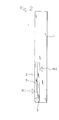
- An inner sound hole 26 and an outer sound hole 27 are opened in an inner wall 22 and an outer wall 24 of the member, respectively.
- the places where the sound holes 26 and 27 are opened are shifted from each other in a far-and-near direction with respect to the center position of opening and closing movements of the openable/closable member 2, i.e., the center position of the hinge 3.
- the inner sound hole 26 is biasedly located in a position which is close to the free end of the openable/closable member 2
- the outer sound hole 27 is biasedly located in a position which is close to the center position of opening and closing movements which is the center position of the hinge 3.
- the place where the inner sound hole 26 is opened is indicted by a triangular mark M1
- the place where the outer sound hole 27 is opened is indicted by a triangular mark M2.
- a microphone 5 is placed inside the openable/closable member 2.
- the microphone 5 is formed into a flat shape, and clampingly held in a place in the vicinity of the hinge 3 by an arcuate support member 23 disposed on the inner wall 22 of the openable/closable member 2, and an annular support member 25 disposed on the outer wall 24.
- the microphone 5 is placed in an intermediate position between the walls 22 and 24.
- the microphone 5 is a bidirectional close-talking microphone.
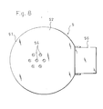
- an opening of a flat circular case 51 is closed by a shield plate 53, and a front sound hole 54 and a rear sound hole 55 are opened in a front plate 52 of the case 51 and the shield plate 53, respectively.
- a shield plate 53 As illustratively shown in Fig.
- a diaphragm 61 and a circuit board (not shown) are accommodated in the case 51, and the circuit board partly protrudes to the outside of the case 51.
- the protrusion portion 56 comprises a grounding terminal 57 and an output terminal 58.
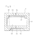
- the inner space of the hollow case 51 is partitioned by the diaphragm 61 into a front chamber 62 and a rear chamber 63.
- the front sound hole 54 faces the front chamber
- the rear sound hole 55 faces the rear chamber 63.
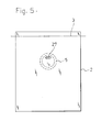
- a partition plate portion 28 is disposed on the inner wall 22 of the openable/closable member 2.
- a sound path 64 through which the inner sound hole 26 communicates with the front sound hole 54 (see Fig. 8 or 9) of the microphone 5 is formed by the space surrounded by the partition plate portion 28.
- a sound path 65 through which the outer sound hole 27 communicates with the rear sound hole 55 (see Fig. 7 or 9) of the microphone 5 is formed by the space surrounded by the annular support member 25 disposed on the outer wall 24 of the openable/closable member 2.
- both the pressure of a sound wave which enters the front chamber 62 through the front sound hole 54, and that of a sound wave which enters the rear chamber 63 through the rear sound hole 55 are applied to the diaphragm 61.
- the sound source is in a position which is close to the front sound hole 54 and remote from the rear sound hole 55, a notable difference is produced between the pressures of the sound waves respectively applied to the front and rear faces of the diaphragm 61, and the pressure applied to the front face of the diaphragm 61 is very larger than that applied to the rear face.
- the microphone exhibits a high sensitivity with respect to the sound wave which enters the front chamber 62 through the front sound hole 54, and the sensitivity with respect to the sound wave which enters the rear chamber 63 through the rear sound hole 55 is very low.
- sound pickup of a large S/N ratio (with reduced noise) is enabled. This is called the proximity effect of the close-talking microphone.
- a sound source is in a position which is close to the rear sound hole 55 and remote from the front sound hole 54, a notable difference is produced between sound pressures respectively applied to the front and rear faces of the diaphragm 61, and the pressure applied to the rear face of the diaphragm 61 is very larger than that applied to the front face.
- the microphone exhibits a high sensitivity with respect to the sound wave which enters the rear chamber 63 through the rear sound hole 55, and the sensitivity with respect to the sound wave which enters the front chamber 62 through the front sound hole 54 is very low.
- sound pickup of a large S/N ratio (with reduced noise) is enabled.
- the close-talking microphone exerts the proximity effect.
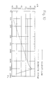
- Fig. 10 exemplarily shows characteristic curves illustrating the proximity effect.
- the solid line shows a characteristic curve in the case where a sound source is in a position which is close (separated by 1 cm) to the diaphragm
- the broken line shows a characteristic curve in the case where a sound source is in a position which is remote (separated by 50 cm) from the diaphragm.
- a close-talking microphone when a sound source is in a position close to the diaphragm, a close-talking microphone exhibits a high sensitivity as indicated by the solid line, and, when a sound source is in a position remote from the diaphragm, the microphone exhibits a low sensitivity as indicated by the broken line, with the result that sound pickup of a very large S/N ratio is enabled.
- a sound wave which enters through the inner sound hole 26 acts on the diaphragm 61 from the front face side of the diaphragm 61 via the sound path 64 and the front sound hole 54 of the microphone 5, and, when the openable/closable member 2 is closed as shown in Fig. 2, a sound wave which enters through the outer sound hole 27 acts on the diaphragm 61 from the rear face side of the diaphragm 61 via the other sound path 65 and the rear sound hole 55 of the microphone 5.
- the place where the inner sound hole 26 is opened is biasedly located in a position which is close to the free end of the openable/closable member 2, and the outer sound hole 27 is biasedly located in a position which is close to the center position of opening and closing movements of the openable/closable member 2.
- the positions of the sound holes are close to the mouth in both the cases where the openable/closable member 2 is opened, and where the member is closed.
- a close-talking microphone is used as the microphone 5.
- the proximity effect of the close-talking microphone can be exerted in both the cases where the openable/closable member is opened, and where the member is closed, so that an excellent speech quality is obtained.
- the distance between the inner sound hole 26 and the mouth when the openable/closable member 2 is opened is shorter than that between the outer sound hole 27 and the mouth when the openable/closable member 2 is closed, and the sound path 65 through which the outer sound hole 27 communicates with the rear sound hole 55 of the microphone 5 is shorter than the sound path 64 through which the inner sound hole 26 communicates with the front sound hole 54 of the microphone 5. Therefore, the proximity effect of the close-talking microphone can be exerted uniformly in both the cases where speech is conducted while the openable/closable member 2 is opened, and where speech is conducted while the openable/closable member 2 is closed. Consequently, the embodiment attains an effect that, irrespective of whether the openable/closable member 2 is opened or closed, a uniform stable speech quality of a very large S/N ratio can be obtained.
Landscapes
- Engineering & Computer Science (AREA)
- Signal Processing (AREA)
- Telephone Set Structure (AREA)
- Details Of Audible-Bandwidth Transducers (AREA)
- Obtaining Desirable Characteristics In Audible-Bandwidth Transducers (AREA)
Abstract
Description
Claims (4)
- A portable communication apparatus comprising: a main unit of said portable apparatus; a flat hollow openable/closable member which is attached in an openable and closable manner to said portable apparatus main unit; and a microphone which is placed inside said openable/closable member, wherein
said apparatus has:said microphone that is configured by a bidirectional microphone in which a sound pressure is applied to a diaphragm from both front and rear sides;inner and outer sound holes which are opened respectively in inner and outer side walls of said openable/closable member, places where said sound holes are opened being shifted from each other in a far-and-near direction with respect to a center position of opening and closing movements of said openable/closable member; andsound paths which are formed inside said openable/closable member to allow said sound holes to face front and rear faces of said diaphragm, respectively. - A portable communication apparatus according to claim 1, wherein said place where said inner sound hole is opened is remoter from said center position of opening and closing movements of said openable/closable member, than said place where said outer sound hole is opened.
- A portable communication apparatus according to claim 1, wherein said microphone is a close-talking microphone having a function in which a sensitivity is high with respect to a close sound source, and low with respect to a remote sound source, said inner sound hole is biasedly located in a position which is close to a free end of said openable/closable member, and said outer sound hole is biasedly located in a position which is close to said center position of opening and closing movements.
- A microphone device for a portable communication apparatus that is to be placed inside a flat hollow openable/closable member which is attached in an openable and closable manner to a main unit of said portable apparatus, wherein
said microphone device has:a hollow case;a diaphragm which is incorporated into said case to partition an inner space of said case into front and rear chambers;front and rear sound holes which are opened in said case, said front sound hole facing said front chamber, said rear sound hole facing said rear chamber;a sound path which is formed inside said openable/closable member to cause said front sound hole to face an inner sound hole that is biasedly located in a position which is close to a free end of an inner wall of said openable/closable member; andanother sound path which is formed inside said openable/closable member to cause said rear sound hole to face an outer sound hole that is biasedly located in a position which is close to a center position of opening and closing movements of said openable/closable member.
Applications Claiming Priority (2)
| Application Number | Priority Date | Filing Date | Title |
|---|---|---|---|
| JP2001300295 | 2001-09-28 | ||
| JP2001300295A JP3746217B2 (en) | 2001-09-28 | 2001-09-28 | Portable communication device and microphone device for the same |
Publications (2)
| Publication Number | Publication Date |
|---|---|
| EP1298889A2 true EP1298889A2 (en) | 2003-04-02 |
| EP1298889A3 EP1298889A3 (en) | 2004-09-29 |
Family
ID=19120895
Family Applications (1)
| Application Number | Title | Priority Date | Filing Date |
|---|---|---|---|
| EP02021197A Withdrawn EP1298889A3 (en) | 2001-09-28 | 2002-09-24 | Portable communication apparatus and microphone device for the apparatus |
Country Status (4)
| Country | Link |
|---|---|
| US (1) | US7187956B2 (en) |
| EP (1) | EP1298889A3 (en) |
| JP (1) | JP3746217B2 (en) |
| CN (1) | CN100452802C (en) |
Families Citing this family (14)
| Publication number | Priority date | Publication date | Assignee | Title |
|---|---|---|---|---|
| US8095073B2 (en) * | 2004-06-22 | 2012-01-10 | Sony Ericsson Mobile Communications Ab | Method and apparatus for improved mobile station and hearing aid compatibility |
| TWM270153U (en) * | 2004-09-10 | 2005-07-11 | Da-Shuo Jang | A universal holder for digital devices or electronic products used in car |
| US8483776B2 (en) * | 2005-07-27 | 2013-07-09 | Sony Corporation | Acoustic path for a wireless communications device |
| KR101143782B1 (en) | 2005-09-06 | 2012-05-11 | 엘지전자 주식회사 | Microphone and the control apparatus and the method thereof |
| US8005241B2 (en) * | 2006-10-10 | 2011-08-23 | Rane Corporation | Mute circuit for a microphone |
| EP2007167A3 (en) * | 2007-06-21 | 2013-01-23 | Funai Electric Advanced Applied Technology Research Institute Inc. | Voice input-output device and communication device |
| JP5257920B2 (en) * | 2007-10-16 | 2013-08-07 | 船井電機株式会社 | Mobile phone and microphone unit |
| JP2009135661A (en) * | 2007-11-29 | 2009-06-18 | Funai Electric Co Ltd | Microphone unit, manufacturing method thereof and sound input device |
| JP5128919B2 (en) * | 2007-11-30 | 2013-01-23 | 船井電機株式会社 | Microphone unit and voice input device |
| JP5502313B2 (en) * | 2008-12-05 | 2014-05-28 | 船井電機株式会社 | Microphone unit |
| JP2011082723A (en) | 2009-10-06 | 2011-04-21 | Hosiden Corp | Unidirectional microphone |
| US9407984B2 (en) * | 2011-02-24 | 2016-08-02 | Htc Corporation | Method and apparatus for adjusting sound quality |
| CN106412785B (en) * | 2016-07-07 | 2021-12-28 | 福建太尔集团股份有限公司 | Multifunctional bone conduction hearing aid |
| CN111432053A (en) * | 2020-03-27 | 2020-07-17 | 歌尔微电子有限公司 | Mobile terminal capable of realizing remote pickup |
Family Cites Families (10)
| Publication number | Priority date | Publication date | Assignee | Title |
|---|---|---|---|---|
| JPH0548451A (en) | 1991-08-08 | 1993-02-26 | Matsushita Electric Ind Co Ltd | Frequency synthesizer device |
| JPH0585144A (en) | 1991-09-30 | 1993-04-06 | Mazda Motor Corp | Air conditioner for vehicle |
| US5276916A (en) * | 1991-10-08 | 1994-01-04 | Motorola, Inc. | Communication device having a speaker and microphone |
| JP2000507065A (en) * | 1996-12-17 | 2000-06-06 | コーニンクレッカ フィリップス エレクトロニクス エヌ ヴィ | Cordless telephone |
| JPH1132107A (en) * | 1997-07-08 | 1999-02-02 | Matsushita Electric Ind Co Ltd | Portable communication equipment |
| JP3209150B2 (en) * | 1997-08-12 | 2001-09-17 | 日本電気株式会社 | Foldable portable wireless communication device |
| JPH11177664A (en) * | 1997-12-13 | 1999-07-02 | Matsushita Electric Ind Co Ltd | Microphone device for mobile phone |
| JP3541673B2 (en) * | 1998-04-21 | 2004-07-14 | 株式会社デンソー | Telephone equipment |
| GB2355128B (en) * | 1999-10-08 | 2003-04-09 | Nokia Mobile Phones Ltd | Portable electronics device |
| US6751487B1 (en) * | 2000-02-08 | 2004-06-15 | Ericsson, Inc. | Turn around cellular telephone |
-
2001
- 2001-09-28 JP JP2001300295A patent/JP3746217B2/en not_active Expired - Fee Related
-
2002
- 2002-09-04 CN CNB021322996A patent/CN100452802C/en not_active Expired - Fee Related
- 2002-09-17 US US10/245,901 patent/US7187956B2/en not_active Expired - Fee Related
- 2002-09-24 EP EP02021197A patent/EP1298889A3/en not_active Withdrawn
Also Published As
| Publication number | Publication date |
|---|---|
| CN1409528A (en) | 2003-04-09 |
| US20030064687A1 (en) | 2003-04-03 |
| US7187956B2 (en) | 2007-03-06 |
| CN100452802C (en) | 2009-01-14 |
| JP2003110676A (en) | 2003-04-11 |
| JP3746217B2 (en) | 2006-02-15 |
| EP1298889A3 (en) | 2004-09-29 |
Similar Documents
| Publication | Publication Date | Title |
|---|---|---|
| US6144738A (en) | Telephone handset with enhanced handset/handsfree receiving and alerting audio quality | |
| KR100724116B1 (en) | Mobile communication terminal with built-in antenna | |
| US8768405B2 (en) | Portable terminal with first and second sound emission portions | |
| US7187956B2 (en) | Portable communication apparatus and microphone device for the apparatus | |
| KR100329134B1 (en) | Portable electric device with a speaker assembly | |
| US6064894A (en) | Portable radio telephone having improved speaker and housing assembly for handsfree and private operation | |
| US6134336A (en) | Integrated speaker assembly of a portable electronic device | |
| US20060113143A1 (en) | Acoustic device | |
| GB2355128A (en) | Single transducer for hands-free and private use has separate acoustic paths with different attenuations | |
| EP1583391A1 (en) | A communications unit with arrangment for loud reproduction of sound | |
| US5216711A (en) | Telephone handset including directional microphone module | |
| KR100743005B1 (en) | Portable terminal apparatus | |
| JPH06232950A (en) | Wrist watch type small telephone | |
| CN1135879C (en) | Foldable hand-held telephone | |
| WO2007060730A1 (en) | Portable terminal | |
| JP4571632B2 (en) | Speaker placement for foldable terminals | |
| EP0852891B1 (en) | Mounting arrangement for a noise cancelling microphone | |
| US20070135180A1 (en) | Shaped loudspeaker output in a communications handset | |
| EP0965215A1 (en) | Portable speech communication apparatus with sound channel in swingable flip | |
| KR200216321Y1 (en) | Earphone with microphone | |
| KR100501303B1 (en) | Speaker structure of mobile phone having mulit speaker hole | |
| KR200285857Y1 (en) | A mobile phone of folder type | |
| EP1098497A2 (en) | Acoustic echo suppression mechanism for a portable radio apparatus | |
| EP1564970B1 (en) | Electro-acoustic transducer for a portable communication device | |
| JP4394927B2 (en) | Foldable mobile terminal |
Legal Events
| Date | Code | Title | Description |
|---|---|---|---|
| PUAI | Public reference made under article 153(3) epc to a published international application that has entered the european phase |
Free format text: ORIGINAL CODE: 0009012 |
|
| AK | Designated contracting states |
Kind code of ref document: A2 Designated state(s): AT BE BG CH CY CZ DE DK EE ES FI FR GB GR IE IT LI LU MC NL PT SE SK TR Designated state(s): AT BE BG CH CY CZ DE DK EE ES FI FR GB GR IE IT LI LU MC NL PT SE SK TR |
|
| AX | Request for extension of the european patent |
Extension state: AL LT LV MK RO SI |
|
| PUAL | Search report despatched |
Free format text: ORIGINAL CODE: 0009013 |
|
| AK | Designated contracting states |
Kind code of ref document: A3 Designated state(s): AT BE BG CH CY CZ DE DK EE ES FI FR GB GR IE IT LI LU MC NL PT SE SK TR |
|
| AX | Request for extension of the european patent |
Extension state: AL LT LV MK RO SI |
|
| 17P | Request for examination filed |
Effective date: 20050329 |
|
| AKX | Designation fees paid |
Designated state(s): FI FR SE |
|
| REG | Reference to a national code |
Ref country code: DE Ref legal event code: 8566 |
|
| RAP1 | Party data changed (applicant data changed or rights of an application transferred) |
Owner name: HOSIDEN CORPORATION |
|
| 17Q | First examination report despatched |
Effective date: 20080403 |
|
| STAA | Information on the status of an ep patent application or granted ep patent |
Free format text: STATUS: THE APPLICATION IS DEEMED TO BE WITHDRAWN |
|
| 18D | Application deemed to be withdrawn |
Effective date: 20120303 |