EP1298749A1 - Humidification cell and fuel cell installation - Google Patents
Humidification cell and fuel cell installation Download PDFInfo
- Publication number
- EP1298749A1 EP1298749A1 EP01123170A EP01123170A EP1298749A1 EP 1298749 A1 EP1298749 A1 EP 1298749A1 EP 01123170 A EP01123170 A EP 01123170A EP 01123170 A EP01123170 A EP 01123170A EP 1298749 A1 EP1298749 A1 EP 1298749A1
- Authority
- EP
- European Patent Office
- Prior art keywords
- humidification
- membrane
- fuel cell
- support element
- cell
- Prior art date
- Legal status (The legal status is an assumption and is not a legal conclusion. Google has not performed a legal analysis and makes no representation as to the accuracy of the status listed.)
- Withdrawn
Links
Images

Classifications
-
- H—ELECTRICITY
- H01—ELECTRIC ELEMENTS
- H01M—PROCESSES OR MEANS, e.g. BATTERIES, FOR THE DIRECT CONVERSION OF CHEMICAL ENERGY INTO ELECTRICAL ENERGY
- H01M8/00—Fuel cells; Manufacture thereof
- H01M8/04—Auxiliary arrangements, e.g. for control of pressure or for circulation of fluids
-
- H—ELECTRICITY
- H01—ELECTRIC ELEMENTS
- H01M—PROCESSES OR MEANS, e.g. BATTERIES, FOR THE DIRECT CONVERSION OF CHEMICAL ENERGY INTO ELECTRICAL ENERGY
- H01M8/00—Fuel cells; Manufacture thereof
- H01M8/04—Auxiliary arrangements, e.g. for control of pressure or for circulation of fluids
- H01M8/04082—Arrangements for control of reactant parameters, e.g. pressure or concentration
- H01M8/04089—Arrangements for control of reactant parameters, e.g. pressure or concentration of gaseous reactants
- H01M8/04119—Arrangements for control of reactant parameters, e.g. pressure or concentration of gaseous reactants with simultaneous supply or evacuation of electrolyte; Humidifying or dehumidifying
-
- H—ELECTRICITY
- H01—ELECTRIC ELEMENTS
- H01M—PROCESSES OR MEANS, e.g. BATTERIES, FOR THE DIRECT CONVERSION OF CHEMICAL ENERGY INTO ELECTRICAL ENERGY
- H01M8/00—Fuel cells; Manufacture thereof
- H01M8/24—Grouping of fuel cells, e.g. stacking of fuel cells
-
- H—ELECTRICITY
- H01—ELECTRIC ELEMENTS
- H01M—PROCESSES OR MEANS, e.g. BATTERIES, FOR THE DIRECT CONVERSION OF CHEMICAL ENERGY INTO ELECTRICAL ENERGY
- H01M2300/00—Electrolytes
- H01M2300/0017—Non-aqueous electrolytes
- H01M2300/0065—Solid electrolytes
- H01M2300/0082—Organic polymers
-
- Y—GENERAL TAGGING OF NEW TECHNOLOGICAL DEVELOPMENTS; GENERAL TAGGING OF CROSS-SECTIONAL TECHNOLOGIES SPANNING OVER SEVERAL SECTIONS OF THE IPC; TECHNICAL SUBJECTS COVERED BY FORMER USPC CROSS-REFERENCE ART COLLECTIONS [XRACs] AND DIGESTS
- Y02—TECHNOLOGIES OR APPLICATIONS FOR MITIGATION OR ADAPTATION AGAINST CLIMATE CHANGE
- Y02E—REDUCTION OF GREENHOUSE GAS [GHG] EMISSIONS, RELATED TO ENERGY GENERATION, TRANSMISSION OR DISTRIBUTION
- Y02E60/00—Enabling technologies; Technologies with a potential or indirect contribution to GHG emissions mitigation
- Y02E60/30—Hydrogen technology
- Y02E60/50—Fuel cells
Definitions
- the invention relates to a humidification cell Fuel cell device with two outer plates, between which a gas room, a humidification water room and one water-permeable membrane separating the two rooms is.
- a single fuel cell supplies an operating voltage of a maximum of about 1.1 V. Therefore, a variety of fuel cells combined into a fuel cell arrangement, for example to a stack of planar fuel cells is part of a fuel cell block. By connecting the fuel cells of the arrangement in series the operating voltage of the arrangement can be 100 V and more be.
- a planar fuel cell includes a flat electrolyte, on its flat side a flat anode and on the other flat side of which is also a flat cathode borders. These two electrodes form together with the electrolyte a so-called electrolyte electrode unit, the hereinafter also the electrolyte arrangement for the sake of simplicity is called. Adjacent to the anode is an anode gas space and a cathode gas space is arranged adjacent to the cathode. Between the anode gas space of a fuel cell and the cathode gas space one adjacent to this fuel cell A composite circuit board is arranged in the fuel cell.
- the Composite circuit board provides an electrical connection between the anode of the first-mentioned fuel cell and the cathode the second-mentioned fuel cell.
- Dependent on The composite circuit board is of the type of the fuel cell for example as a single metallic plate or as designed a cooling element, the two stacked on top of each other Includes plates with an intermediate cooling water space.
- the fuel cells are in a fuel cell stack further components, such as electrically conductive layers, seals or Pressure pad.
- the fuel cells of a fuel cell arrangement are during operation with process gases - i.e. a hydrogen-containing one Fuel gas and an oxygen-containing oxidation gas - provided.
- process gases i.e. a hydrogen-containing one Fuel gas and an oxygen-containing oxidation gas - provided.
- Some embodiments of low temperature fuel cells especially fuel cells with a Polymer electrolyte membrane (PEM fuel cells)
- PEM fuel cells Polymer electrolyte membrane
- Operating gases humidified for operation be in a suitable facility, such as a liquid ring compressor or a membrane humidifier, saturated with water vapor.
- the humidification cells are as Membrane humidifier with an operating gas space, a humidification water space and one arranged between the two rooms water permeable membrane. Before the operating gases the fuel cells of the fuel cell stack are passed through the humidification cells, are moistened there and then flow without the To leave the fuel cell block again in the fuel cell stack.
- the water-permeable one lies in the humidification cells Membrane arranged directly on both sides of the membrane Outer plates of the humidification cells.
- a fuel cell device Under a fuel cell device is a fuel cell arrangement in connection with a humidifier and possibly other utilities Roger that.
- the fuel cell arrangement comprises one Variety of stacks on top of one another stacked planar fuel cells.
- the fuel cell device can for example use a fuel cell block one or more stacks of humidification cells and one or multiple fuel cell stacks.
- the humidification cells can also run a certain distance from the fuel cells be located away. It is also possible a stack of mixed fuel cells and humidification cells.
- Impairment of the humidification performance of the water-permeable Membrane due to the partial contact of the membrane on one of the outer panels can be eliminated by the membrane is freely suspended between the outer plates becomes.
- the membrane is so soft and flexible, that they always appear at least partially in operation hugs one of the outer panels.
- the membrane With a water permeable Support element that is between the membrane and a the outer plates is arranged, the membrane is in the area of the support element kept spaced from the outer plate.
- the support element Depending on which side of the membrane the support element is arranged, penetrates the dampening water either first the support element and then the membrane or first the membrane and then the support element and thus arrives to the operating gas to be humidified.
- the support element can, for example, be fixed with the membrane be connected.
- the membrane is covered with a sufficient stiffness provided support element in the desired Position between the gas space and the dampening water space held so that the membrane on none of the outer panels is applied.
- the membrane lies loosely and detachably on the support element and is, for example, by the operating gas pressure or the dampening water pressure is pressed against the support element. In this way too, the membrane is in a predetermined Position held.
- the support element expediently does not fill the entire one Gas space or humidification water space, but still leaves part of the room free so the flow of the process gas or the dampening water through the gas space or the dampening water space not in an operation of the humidification cell impairing extent by the support element is disturbed.
- the membrane is particularly reliable in a desired one Position held when both sides of the membrane are on Support element is arranged. Regardless of whether the membrane is firmly connected to one or both support elements or is releasably clamped between the support elements is in Area of the support elements a partial covering of the membrane not possible due to the outer panels. This is one reliably ensures high humidification performance of the membrane.
- a particularly stable storage of the membrane and a special simple structure of the humidification cell is achieved that the first outer plate, the first support element, the membrane, the second support element and the second outer plate each abut each other.
- the outer panels expediently channels or embossing through which the Operating gas or the dampening water along the outer plate and along the support element abutting the outer plate can flow.
- the Humidification cell a particularly stable and largely against Pressure-resistant composite. This configuration of the The invention is particularly suitable for very flat humidification cells with a very flat gas space and / or humidification water space.
- the support element can be, for example, a wire mesh Wire mesh or designed as an expanded metal his. However, it is important to ensure that a metallic Support element has no sharp edges that the in usually damage soft membrane.
- Mechanical for the membrane is safe and particularly inexpensive to manufacture a support element made of a fiber mesh or a fiber felt is made.
- fibers are suitable Plastic fibers, cellulose fibers or other fibers that are chemically sufficiently stable to the process gases.
- carbon paper has proven to be particularly advantageous proven to produce the support member.
- carbon paper has sufficient stability even against pure oxygen and pure hydrogen in connection with water on and is also sufficiently permeable to water to be effective Ensure operation of the humidification cell.
- a particularly high humidification capacity of the humidification cell is achieved when the support element is hydrophilic.
- Hydrophilic support element sucks in and guides the water particularly effective to the place where the water evaporates.
- Hydrophilicity of the carbon paper for example through a chemical treatment.
- the support element can be the dampening water or the operating gas Cover the accessible area of the membrane completely.
- good support of the membrane is also guaranteed if the support element, for example through recesses in the support element, only part of the flat side of the Membrane covered. This gives unimpeded access from the dampening water and operating gas to the membrane, whereby the humidification capacity of the humidification cell is increased.
- the humidification cell a covering device on the support element in the area of an equipment inlet.
- the resource inlet is the opening of a line or one Channel into the gas or humidification water space of the humidification cell, by the during the operation of the humidification cell Operating gas and dampening water - in the following equipment called - in the gas space or the humidification water space flows.
- the resources flow through one Equipment inlet in the respective room of the humidification cell. It has been shown that depending on the design of the equipment room the equipment flow from the equipment inlet in the process gas or humidification water room is disturbed by the support element.
- the resource flows out of the equipment inlet at a relatively high speed in the respective room and meets there onto the support element or flows at the relatively high speed along the support member.
- a cover device which the support element in the area of an equipment inlet covers to be largely avoided.
- a covering device can, for example, a film, a metal coating Piece of plastic or a small sheet of metal are used, with which the support element around an equipment inlet is separated from the flow of equipment. The covering device directs the equipment out of the equipment inlet in the respective room and ensures that the equipment without creating significant turbulence in flows into the room.
- the membrane made of the same material as the electrolyte the electrolyte arrangement of the fuel cells from the fuel cell device.
- Suitable as such a material especially a polymer called NAFION from the company DuPont from Wilmington, Delaware.
- Electrodes such as support elements must be sufficient chemical stability against the mixture of process gases and have water and they must be permeable for water and process gases. Therefore, the electrodes and the support element made of the same carrier material become.
- the specific properties of the electrodes or the support element are treated further of this carrier material. For example, it will Fiber braid or the fiber felt for the support element a chemical treatment made hydrophilic.
- the Humidification cells a membrane arrangement from a membrane and have support elements arranged on both sides of the membrane, the membrane arrangement and the electrolyte arrangement are identical in structure and dimensions.
- the humidification cell has an analog structure like a fuel cell the fuel cell device: instead of the electrolyte the humidification cell of the fuel cell Membrane, which expediently from the same material how the electrolyte is.
- the support elements on the two flat Arranged sides of the membrane are in the Humidification cell, the support elements on the two flat Arranged sides of the membrane.
- the support elements however not be firmly connected to the membrane, but can lie loosely on the membrane.
- the support elements have the same carrier material on like the electrodes.
- Another advantage is the same structure of the humidification cell and fuel cell in a fuel cell device reached. This simplifies production this fuel cell device and is lighter standardized.
- a fuel cell are on both sides the electrolyte arrangement of the oxidation gas space and the fuel gas space arranged.
- An analogous way is in the humidification cell on both sides of the membrane arrangement the gas space and the humidification water room arranged.
- the humidification cell delimited on both sides of their flat sides by outer plates.
- the outer plates are expediently of the same type Material and kept in the same shape as the composite circuit boards the fuel cell.
- a further simplification of the manufacture of the fuel cell device is achieved by the electrolyte arrangement and the membrane arrangement is surrounded by the same sealing material are.
- the sealing material holds the assemblies in place and ensures a gas-tight seal of the gas spaces as well as the humidification water space compared to the environment of the Fuel cell device.
- the production of fuel cells and humidification cells can thus be standardized. Also simplified the structure of the fuel cell device, since the components of the device surrounding the cells, such as tie rods, piping or a Cover around the fuel cell device, not to different ones Adapt sizes of humidification cells and fuel cells are.
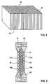
- Figure 1 is a rectangular plan view in a schematic and planar humidification cell 1, which one embedded in a frame made of a sealing material 3 and Diaphragm 5 shown cut open. Under the membrane 5 is also a cut-away representation Support element 7 visible. Is below the support element 7 an outer plate 9 shown as a sheet with a Embossing structure 11 is designed. The embossed structure 11 exists from round elevations or depressions within the Outer plate 9. Between the outer plate 9 and the support element 7, a cover device 13 is attached. The covering device 13 is in the area of an equipment inlet 15 arranged.
- FIG. 2 shows a section through the humidification cell 1 along the line A-A.
- the humidification cell 1 is part of a Humidification cell stack of a fuel cell device. Fuel gas flows during operation of the humidification cell 1 through the axial channel 17 of the humidification cell 1. The axial channel 17 is parallel to the stacking direction of the humidification cell stack aligned. One branches off from the axial channel 17 Radial channel 19 to one of the humidification cells 1 of the humidification cell stack from. The fuel gas flows through the radial channel 19 and later through the equipment inlet 15 and then enters the gas space 21 of the Humidification cell 1. After leaving the equipment inlet 15 removes the fuel gas without significant turbulence to form on the one hand on the cover device 13 and on the other hand along the outer plate 9 of the humidification cell 1.
- the outer plate 9 is designed as a heating element that is composed of two metal sheets. Between the metal sheets there is a heating water room through which the operation of the humidification cell 1 warm heating water flows. This heating water heats both through the humidification cell 1 flowing fuel gas as well as the dampening water to approximately the temperature of the fuel cells Fuel cell device.
- the fuel gas is moistened with dampening water and after flowing through the gas space 21 reaches Resource outlet 23 of the gas space 21.
- Resource outlet 23 of the gas space 21.
- This is also in the area of the equipment outlet 23 Support element 7b covered by a further covering device 24, to prevent turbulence when the fuel gas flows into the Prevent resource outlet 23.
- FIG. 3 shows a section through the humidification cell 1 along the line B-B shown in Figure 1.
- This Section is made along an axial channel 25 which during the operation of the humidification cell 1 humidification water leads.
- the dampening water flows through the axial channel 25 and passes through the radial channel 27 to a further equipment inlet 29.
- This resource inlet 29 The dampening water flows through the dampening water space 31, and flows between the outer plate 9 and a covering device 33.
- the dampening water then arrives to the support element 7a, which is a chemical Process is made of carbon paper made hydrophilic. A part of the dampening water penetrates the hydrophilic carbon paper, and reaches the membrane 5.
- the two support elements 7a and 7b releasably lie on the water-permeable Membrane 5 and cover the flat outer sides the membrane 5 completely except for a narrow outer edge.
- the two support elements 7a and 7b form together with the membrane 5, a membrane arrangement between the two outer plates 9 of the humidification cell 1 clamped is.
- the support elements 7a, 7b are thus on one side on the membrane 5 and on the other side on one of the Outer plates 9 on.
- Through the support elements 7a, 7b Membrane 5 held firmly in position. Also effect the support elements 7a, 7b that the membrane 5 at no point can touch the outer plate 9 and thus from part of the Outer plates 9 is covered.
- the dampening water and that Operating gas can thus run along essentially the entire Surface of the membrane 5 through the support element 7a to the membrane 5 penetrate.
- a fuel cell device is shown in a schematic illustration in FIG 41 shown in the form of a fuel cell block.
- the fuel cell device 41 comprises a stack from humidification cells 43 and a stack of fuel cells 45.
- the humidification cells 43 have the same Width and height on how the fuel cells 45. This the fuel cell block has along the stacking direction of the Humidification cells 43 and the fuel cells 45 along one Stack axis an even width and height.
- the humidification cells 43 have the same thickness as that Fuel cells 45 so that the outer shape and the outer Dimensions of the humidification cells 43 are the same as the outer Shape and external dimensions of the fuel cells 45th
- FIG. 5 A section through a fuel cell 45 of the fuel cell device 41 is shown in FIG. 5.
- the fuel cell 45 comprises an electrolyte 51 and two electrodes 53a and 53b, each on the flat side of the electrolyte 51 are arranged.
- a fuel gas space borders on the electrode 53a 55, between the electrode 53a and a composite circuit board 57 of the fuel cell 45 is arranged.
- To the electrode 53b delimits an oxidizing gas space 59, which is between the Electrode 53b and another composite printed circuit board 57b
- Fuel cell 45 is arranged.
- the composite circuit boards 57a and 57b are cooling elements which consist of two sheets, that enclose a cooling water space between them.
- Cooling water flows during operation of the fuel cell 45 through the composite circuit boards 57a, 57b for cooling the fuel cell 45.
- Oxidation gas flows and passes through a radial channel into the oxidation gas space 59.
- Both the membrane arrangement of the humidification cell 1 and the electrolyte arrangement of the fuel cell 45 is in one Framed from a sealing material 3 or 63.
- the Sealing material 3 of the humidification cell 1 is the same material like the sealing material 63 of the fuel cell 45.
- the support elements 7a, 7b are made of the same carrier material made like the electrodes 53a, 53b, namely from carbon paper. However, the carbon paper of the electrodes 53a and 53b is in contrast to the support elements 7a and 7b with one coated with additional material for waterproofing.
- the electrodes 53a, 53b have the electrolyte 51 on them facing side a coating of platinum, which as Catalyst for the electrochemical reaction within the Fuel cell 45 is used.
- the electrolyte 51 is like the water-permeable one Membrane 5 made from NAFION. Moreover the membrane arrangement of the humidification cell 1 has the same Dimensions based on how the electrolyte arrangement of the fuel cell 45. Through the analog structure of the fuel cell 45 and the humidification cell 1 is the number in the fuel cell device 41 materials used as well as the Number of for the manufacture of the fuel cell device 51 required tools manageable. This reduces the manufacturing costs the humidification cell 1 and the fuel cell device 41st
Abstract
Description
Die Erfindung bezieht sich auf eine Befeuchtungszelle einer Brennstoffzelleneinrichtung mit zwei Außenplatten, zwischen denen ein Gasraum, ein Befeuchtungswasserraum und eine die beiden Räume trennende wasserdurchlässige Membran angeordnet ist.The invention relates to a humidification cell Fuel cell device with two outer plates, between which a gas room, a humidification water room and one water-permeable membrane separating the two rooms is.
In einer Brennstoffzelle wird durch die elektrochemische Verbindung von Wasserstoff (H2) und Sauerstoff (O2) an einem Elektrolyten zu Wasser (H2O) elektrischer Strom mit hohem Wirkungsgrad erzeugt und dies auch ohne Emission von Schadstoffen und Kohlendioxid (CO2), wenn als Brenngas reiner Wasserstoff eingesetzt wird. Die technische Umsetzung dieses Prinzips der Brennstoffzelle hat zu unterschiedlichen Lösungen, und zwar mit verschiedenen Elektrolyten und Betriebstemperaturen zwischen 60°C und 1000°C geführt. In Abhängigkeit von ihrer Betriebstemperatur werden die Brennstoffzellen in Nieder-, Mittel- und Hochtemperatur-Brennstoffzellen eingeteilt, die sich wiederum durch verschiedene technische Ausführungsformen voneinander unterscheiden.In a fuel cell, the electrochemical combination of hydrogen (H 2 ) and oxygen (O 2 ) on an electrolyte to form water (H 2 O) generates electrical current with high efficiency, even without the emission of pollutants and carbon dioxide (CO 2 ), if pure hydrogen is used as the fuel gas. The technical implementation of this principle of the fuel cell has led to different solutions, namely with different electrolytes and operating temperatures between 60 ° C and 1000 ° C. Depending on their operating temperature, the fuel cells are divided into low, medium and high temperature fuel cells, which in turn differ from one another in different technical embodiments.
Eine einzelne Brennstoffzelle liefert eine Betriebsspannung von maximal etwa 1,1 V. Daher wird eine Vielzahl von Brennstoffzellen zu einer Brennstoffzellenanordnung zusammengeschlossen, beispielsweise zu einem Stapel planarer Brennstoffzellen der Bestandteil eines Brennstoffzellenblocks ist. Durch das In-Reihe-Schalten der Brennstoffzellen der Anordnung kann die Betriebsspannung der Anordnung 100 V und mehr betragen.A single fuel cell supplies an operating voltage of a maximum of about 1.1 V. Therefore, a variety of fuel cells combined into a fuel cell arrangement, for example to a stack of planar fuel cells is part of a fuel cell block. By connecting the fuel cells of the arrangement in series the operating voltage of the arrangement can be 100 V and more be.
Eine planare Brennstoffzelle umfasst einen flachen Elektrolyten, an dessen eine flache Seite eine flache Anode und an dessen andere flache Seite eine ebenfalls flache Kathode grenzt. Diese beiden Elektroden bilden zusammen mit dem Elektrolyten eine sogenannte Elektrolyt-Elektroden-Einheit, die im Folgenden der Einfachheit halber auch Elektrolyt-Anordnung genannt wird. Angrenzend an die Anode ist ein Anodengasraum und angrenzend an die Kathode ein Kathodengasraum angeordnet. Zwischen dem Anodengasraum einer Brennstoffzelle und dem Kathodengasraum einer dieser Brennstoffzelle benachbarten Brennstoffzelle ist eine Verbundleiterplatte angeordnet. Die Verbundleiterplatte stellt eine elektrische Verbindung zwischen der Anode der erstgenannten Brennstoffzelle und der Kathode der zweitgenannten Brennstoffzelle her. In Abhängigkeit von der Art der Brennstoffzelle ist die Verbundleiterplatte beispielsweise als eine einzelne metallische Platte oder als ein Kühlelement ausgestaltet, das zwei aufeinander gestapelte Platten mit einem dazwischenliegenden Kühlwasserraum umfasst. Je nach Ausführungsform der Brennstoffzellen befinden sich in einem Brennstoffzellenstapel weitere Bauelemente, wie beispielsweise elektrisch leitende Schichten, Dichtungen oder Druckkissen.A planar fuel cell includes a flat electrolyte, on its flat side a flat anode and on the other flat side of which is also a flat cathode borders. These two electrodes form together with the electrolyte a so-called electrolyte electrode unit, the hereinafter also the electrolyte arrangement for the sake of simplicity is called. Adjacent to the anode is an anode gas space and a cathode gas space is arranged adjacent to the cathode. Between the anode gas space of a fuel cell and the cathode gas space one adjacent to this fuel cell A composite circuit board is arranged in the fuel cell. The Composite circuit board provides an electrical connection between the anode of the first-mentioned fuel cell and the cathode the second-mentioned fuel cell. Dependent on The composite circuit board is of the type of the fuel cell for example as a single metallic plate or as designed a cooling element, the two stacked on top of each other Includes plates with an intermediate cooling water space. Depending on the embodiment of the fuel cells are in a fuel cell stack further components, such as electrically conductive layers, seals or Pressure pad.
Die Brennstoffzellen einer Brennstoffzellenanordnung werden während ihres Betriebs mit Betriebsgasen - also einem wasserstoffhaitigen Brenngas und einem sauerstoffhaltigen Oxidationsgas - versorgt. Manche Ausführungsformen von Niedertemperatur-Brennstoffzellen, insbesondere Brennstoffzellen mit einer Polymer-Elektrolyt-Membran (PEM-Brennstoffzellen), benötigen zum Betrieb befeuchtete Betriebsgase. Diese Betriebsgase werden in einer geeigneten Einrichtung, wie beispielsweise einem Flüssigkeitsringverdichter oder einem Membranbefeuchter, mit Wasserdampf gesättigt. Die Befeuchtungseinrichtung und eventuelle weitere Versorgungseinrichtungen bilden zusammen mit der Brennstoffzellenanordnung die Brennstoffzelleneinrichtung.The fuel cells of a fuel cell arrangement are during operation with process gases - i.e. a hydrogen-containing one Fuel gas and an oxygen-containing oxidation gas - provided. Some embodiments of low temperature fuel cells, especially fuel cells with a Polymer electrolyte membrane (PEM fuel cells) Operating gases humidified for operation. These operating gases be in a suitable facility, such as a liquid ring compressor or a membrane humidifier, saturated with water vapor. The humidifier and possibly form additional utilities together with the fuel cell arrangement, the fuel cell device.
Werden die Betriebsgase durch lange Betriebsgaszuleitungen vom Befeuchter zur Brennstoffzellenanordnung geleitet, so kann auf diesem Weg die Temperatur eines befeuchteten Betriebsgases durch Verlust von Wärme an die Umgebung sinken. Are the operating gases through long operating gas supply lines directed from the humidifier to the fuel cell arrangement, so the temperature of a humidified operating gas sink through loss of heat to the environment.
Dies führt zur Kondensation von Befeuchtungswasser. Die Betriebsgase werden anschließend in den Brennstoffzellen wieder aufgeheizt, wodurch sich ihre relative Feuchtigkeit verringert. Hierdurch wird der stets feucht zu haltende und extrem trockenheitsempfindliche Elektrolyt geschädigt, dessen Lebensdauer sich somit verringert. Es ist daher wünschenswert, dass der Befeuchter möglichst nahe an den Brennstoffzellen angeordnet ist.This leads to the condensation of dampening water. The operating gases are then returned to the fuel cells heated, which reduces their relative humidity. This makes it extremely moist and always keeps it moist Electrolyte sensitive to dryness damaged, its lifespan thus decreases. It is therefore desirable that the humidifier is as close as possible to the fuel cells is arranged.
Aus den Patentschriften US 5,200,278 und US 5,382,478 ist ein Brennstoffzellenblock mit einem Stapel aus planaren Brennstoffzellen und einem Stapel aus planaren Befeuchtungszellen bekannt. Beide Stapel sind unmittelbar benachbart im Brennstoffzellenblock angeordnet. Die Befeuchtungszellen sind als Membranbefeuchter mit einem Betriebsgasraum, einem Befeuchtungswasserraum und einer zwischen den beiden Räumen angeordneten wasserdurchlässigen Membran ausgeführt. Bevor die Betriebsgase den Brennstoffzellen des Brennstoffzellenstapels zugeleitet werden, durchströmen sie die Befeuchtungszellen, werden dort befeuchtet und strömen anschließend ohne den Brennstoffzellenblock wieder zu verlassen in den Brennstoffzellenstapel. In den Befeuchtungszellen liegt die wasserdurchlässige Membran direkt an den beidseitig der Membran angeordneten Außenplatten der Befeuchtungszellen an. Auf der einen Seite der Membran strömt das Befeuchtungswasser und auf der anderen Seite der Membran das Betriebsgas durch Kanäle, die in die jeweilige Außenplatte eingearbeitet sind. Entlang der Stege der Außenplatten jedoch wird die Membran durch die Stege abgedeckt, so dass kein Befeuchtungswasser bzw. Betriebsgas zur Membran gelangen kann. Hierdurch wird die Befeuchtungsleistung der Membran gegenüber vom Befeuchtungswasser frei zugänglichen Membran verringert. Bei der Verwendung von großflächigen Strukturen in der Außenplatte liegt die Membran großflächig an der Außenplatte an, wodurch die Befeuchtungsleistung in erheblichem Umfang vermindert ist. From US 5,200,278 and US 5,382,478 is a Fuel cell block with a stack of planar fuel cells and a stack of planar humidification cells known. Both stacks are immediately adjacent in the fuel cell block arranged. The humidification cells are as Membrane humidifier with an operating gas space, a humidification water space and one arranged between the two rooms water permeable membrane. Before the operating gases the fuel cells of the fuel cell stack are passed through the humidification cells, are moistened there and then flow without the To leave the fuel cell block again in the fuel cell stack. The water-permeable one lies in the humidification cells Membrane arranged directly on both sides of the membrane Outer plates of the humidification cells. On the the dampening water flows on one side of the membrane and on the other side of the membrane the process gas through channels, which are incorporated into the respective outer panel. Along the webs of the outer plates, however, the membrane through the Bridges covered so that no dampening water or operating gas can get to the membrane. This will increase the humidification performance the membrane opposite the dampening water freely accessible membrane reduced. When using of large-scale structures in the outer panel Membrane over a large area on the outer plate, which increases the humidification performance is significantly reduced.
Es ist die Aufgabe der vorliegenden Erfindung, eine Befeuchtungszelle einer Brennstoffzelleneinrichtung anzugeben, die eine hohe Befeuchtungsleistung aufweist.It is the object of the present invention to provide a humidification cell specify a fuel cell device that has a high humidification capacity.
Diese Aufgabe wird durch eine Befeuchtungszelle der eingangs genannten Art gelöst, die erfindungsgemäß ein zwischen der Membran und einer der Außenplatten angeordnetes wasserdurchlässiges Stützelement aufweist.This task is accomplished by a humidification cell at the beginning mentioned type solved according to the invention between the Membrane and one of the outer plates arranged water permeable Has support element.
Unter einer Brennstoffzelleneinrichtung wird eine Brennstoffzellenanordnung in Verbindung mit einer Befeuchtungseinrichtung und gegebenenfalls weiteren Versorgungseinrichtungen verstanden. Die Brennstoffzellenanordnung umfasst hierbei eine Vielzahl von zu einem oder mehreren Stapeln aufeinander gestapelten planaren Brennstoffzellen. Die Brennstoffzelleneinrichtung kann beispielsweise ein Brennstoffzellenblock mit einem oder mehreren Befeuchtungszellenstapeln und einem oder mehreren Brennstoffzellenstapeln sein. Die Befeuchtungszellen können jedoch auch eine gewisse Strecke von den Brennstoffzellen entfernt angeordnet sein. Ebenfalls möglich ist ein Stapel aus gemischt angeordneten Brennstoffzellen und Befeuchtungszellen.Under a fuel cell device is a fuel cell arrangement in connection with a humidifier and possibly other utilities Roger that. The fuel cell arrangement comprises one Variety of stacks on top of one another stacked planar fuel cells. The fuel cell device can for example use a fuel cell block one or more stacks of humidification cells and one or multiple fuel cell stacks. The humidification cells can also run a certain distance from the fuel cells be located away. It is also possible a stack of mixed fuel cells and humidification cells.
Die Beeinträchtigung der Befeuchtungsleistung der wasserdurchlässigen Membran durch das teilweise anliegen der Membran an einer der Außenplatten kann eliminiert werden, indem die Membran frei hängend zwischen den Außenplatten angeordnet wird. In Abhängigkeit von dem Material, aus dem die Membran gefertigt ist, ist die Membran jedoch so weich und biegsam, dass sie sich im Betrieb immer wieder zumindest teilweise an eine der Außenplatten anschmiegt. Mit einem wasserdurchlässigen Stützelement, das zwischen der Membran und einer der Außenplatten angeordnet ist, wird die Membran im Bereich des Stützelements von der Außenplatte beabstandet gehalten. Je nachdem, auf welcher Seite der Membran das Stützelement angeordnet ist, durchdringt das Befeuchtungswasser entweder zuerst das Stützelement und dann die Membran oder zuerst die Membran und dann das Stützelement und gelangt so zum zu befeuchtenden Betriebsgas.Impairment of the humidification performance of the water-permeable Membrane due to the partial contact of the membrane on one of the outer panels can be eliminated by the membrane is freely suspended between the outer plates becomes. Depending on the material from which the membrane is made, the membrane is so soft and flexible, that they always appear at least partially in operation hugs one of the outer panels. With a water permeable Support element that is between the membrane and a the outer plates is arranged, the membrane is in the area of the support element kept spaced from the outer plate. Depending on which side of the membrane the support element is arranged, penetrates the dampening water either first the support element and then the membrane or first the membrane and then the support element and thus arrives to the operating gas to be humidified.
Das Stützelement kann beispielsweise mit der Membran fest verbunden sein. Hierdurch wird die Membran durch das mit einer genügenden Steifigkeit versehene Stützelement in der gewünschten Position zwischen dem Gasraum und dem Befeuchtungswasserraum gehalten, so dass die Membran an keiner der Außenplatten anliegt. In einer alternativen Ausgestaltung der Erfindung liegt die Membran locker und lösbar an dem Stützelement an und wird beispielsweise durch den Betriebsgasdruck oder den Befeuchtungswasserdruck gegen das Stützelement gedrückt. Auch auf diese Weise wird die Membran in einer vorbestimmten Position gehalten.The support element can, for example, be fixed with the membrane be connected. As a result, the membrane is covered with a sufficient stiffness provided support element in the desired Position between the gas space and the dampening water space held so that the membrane on none of the outer panels is applied. In an alternative embodiment of the invention the membrane lies loosely and detachably on the support element and is, for example, by the operating gas pressure or the dampening water pressure is pressed against the support element. In this way too, the membrane is in a predetermined Position held.
Zweckmäßigerweise füllt das Stützelement nicht den gesamten Gasraum bzw. Befeuchtungswasserraum aus, sondern lässt noch einen Teil des Raumes frei, damit der Strom des Betriebsgases oder des Befeuchtungswassers durch den Gasraum bzw. den Befeuchtungswasserraum nicht in einem den Betrieb der Befeuchtungszelle beeinträchtigendem Umfang durch das Stützelement gestört wird.The support element expediently does not fill the entire one Gas space or humidification water space, but still leaves part of the room free so the flow of the process gas or the dampening water through the gas space or the dampening water space not in an operation of the humidification cell impairing extent by the support element is disturbed.
Besonders zuverlässig wird die Membran in einer gewünschten Position gehalten, wenn beidseitig der Membran jeweils ein Stützelement angeordnet ist. Unabhängig davon, ob die Membran fest mit einer oder beiden Stützelementen verbunden ist oder lösbar zwischen den Stützelementen eingeklemmt ist, ist im Bereich der Stützelemente eine teilweise Abdeckung der Membran durch die Außenplatten nicht möglich. Hierdurch ist eine zuverlässig hohe Befeuchtungsleistung der Membran gewährleistet.The membrane is particularly reliable in a desired one Position held when both sides of the membrane are on Support element is arranged. Regardless of whether the membrane is firmly connected to one or both support elements or is releasably clamped between the support elements is in Area of the support elements a partial covering of the membrane not possible due to the outer panels. This is one reliably ensures high humidification performance of the membrane.
Eine besonders stabile Lagerung der Membran und ein besonders einfacher Aufbau der Befeuchtungszelle wird dadurch erreicht, dass die erste Außenplatte, das erste Stützelement, die Membran, das zweite Stützelement und die zweite Außenplatte jeweils aneinander anliegen. Hierbei weisen die Außenplatten zweckmäßigerweise Kanäle oder Prägungen auf, durch die das Betriebsgas oder das Befeuchtungswasser entlang der Außenplatte und entlang des an der Außenplatte anliegenden Stützelements strömen kann. Bei dieser Ausgestaltung bildet die Befeuchtungszelle einen besonders stabilen und weitgehend gegen Druck unempfindlichen Verbund. Diese Ausgestaltung der Erfindung ist besonders geeignet bei sehr flachen Befeuchtungszellen mit einem sehr flachen Gasraum und/oder Befeuchtungswasserraum.A particularly stable storage of the membrane and a special simple structure of the humidification cell is achieved that the first outer plate, the first support element, the membrane, the second support element and the second outer plate each abut each other. Here, the outer panels expediently channels or embossing through which the Operating gas or the dampening water along the outer plate and along the support element abutting the outer plate can flow. In this embodiment, the Humidification cell a particularly stable and largely against Pressure-resistant composite. This configuration of the The invention is particularly suitable for very flat humidification cells with a very flat gas space and / or humidification water space.
Das Stützelement kann beispielsweise als ein Drahtgewebe, ein Drahtgeflecht oder auch als ein Streckgitter ausgestaltet sein. Hierbei ist jedoch darauf zu achten, dass ein metallisches Stützelement keine scharfen Kanten aufweist, die die in der Regel weiche Membran beschädigen. Für die Membran mechanisch ungefährlich und besonders preiswert herzustellen ist ein Stützelement, das aus einem Fasergeflecht oder einem Faserfilz gefertigt ist. Als Fasern eignen sich beispielsweise Kunststofffasern, Zellulosefasern oder andere Fasern, die chemisch ausreichend stabil gegenüber den Betriebsgasen sind.The support element can be, for example, a wire mesh Wire mesh or designed as an expanded metal his. However, it is important to ensure that a metallic Support element has no sharp edges that the in usually damage soft membrane. Mechanical for the membrane is safe and particularly inexpensive to manufacture a support element made of a fiber mesh or a fiber felt is made. For example, fibers are suitable Plastic fibers, cellulose fibers or other fibers that are chemically sufficiently stable to the process gases.
Als besonders vorteilhaft hat sich die Verwendung von Kohlepapier zur Herstellung des Stützelements erwiesen. Kohlepapier weist eine genügende Stabilität auch gegen reinen Sauerstoff und reinen Wasserstoff in Verbindung mit Wasser auf und ist außerdem genügend wasserdurchlässig, um einen effektiven Betrieb der Befeuchtungszelle zu gewährleisten.The use of carbon paper has proven to be particularly advantageous proven to produce the support member. carbon paper has sufficient stability even against pure oxygen and pure hydrogen in connection with water on and is also sufficiently permeable to water to be effective Ensure operation of the humidification cell.
Eine besonders hohe Befeuchtungsleistung der Befeuchtungszelle wird erreicht, wenn das Stützelement hydrophil ist. Ein hydrophiles Stützelement saugt das Wasser an und leitet es besonders effektiv zu dem Ort, wo das Wasser verdampft. Bei der Verwendung von Kohlepapier als Stützelement kann die Hydrophilität des Kohlepapiers, beispielsweise durch eine chemische Behandlung, gesteigert werden. A particularly high humidification capacity of the humidification cell is achieved when the support element is hydrophilic. On Hydrophilic support element sucks in and guides the water particularly effective to the place where the water evaporates. at the use of carbon paper as a support element Hydrophilicity of the carbon paper, for example through a chemical treatment.
Das Stützelement kann die dem Befeuchtungswasser oder dem Betriebsgas zugängliche Fläche der Membran vollständig bedecken. Eine gute Stütze der Membran ist jedoch auch gewährleistet, wenn das Stützelement, beispielsweise durch Aussparungen im Stützelement, nur einen Teil der flachen Seite der Membran bedeckt. Hierdurch erfolgt ein ungehinderterer Zugang vom Befeuchtungswasser und Betriebsgas zur Membran, wodurch die Befeuchtungsleistung der Befeuchtungszelle erhöht wird. Es ist jedoch darauf zu achten, dass das Stützelement mindestens die Hälfte einer flachen Seite der Membran bedeckt, da bei Unterschreitung dieser Fläche eine ausreichende Stützung der in der Regel sehr flexiblen Membran nicht mehr gewährleistet ist.The support element can be the dampening water or the operating gas Cover the accessible area of the membrane completely. However, good support of the membrane is also guaranteed if the support element, for example through recesses in the support element, only part of the flat side of the Membrane covered. This gives unimpeded access from the dampening water and operating gas to the membrane, whereby the humidification capacity of the humidification cell is increased. However, it must be ensured that the support element at least half of a flat side of the membrane is covered there sufficient support if this area is undershot the generally very flexible membrane is no longer guaranteed is.
In bevorzugter Ausgestaltung der Erfindung weist die Befeuchtungszelle eine Abdeckvorrichtung auf, die das Stützelement im Bereich eines Betriebsmitteleinlasses abdeckt. Der Betriebsmitteleinlass ist die Öffnung einer Leitung oder eines Kanals in den Gas- oder Befeuchtungswasserraum der Befeuchtungszelle, durch die während des Betriebs der Befeuchtungszelle Betriebsgas und Befeuchtungswasser - im folgenden Betriebsmittel genannt - in den Gasraum bzw. den Befeuchtungswasserraum strömt. Die Betriebsmittel strömen also durch einen Betriebsmitteleinlass in den jeweiligen Raum der Befeuchtungszelle. Es hat sich gezeigt, dass je nach Ausgestaltung des Betriebsmittelraums der Betriebsmittelstrom aus dem Betriebsmitteleinlass in den Betriebsgas- bzw. Befeuchtungswasserraum durch das Stützelement gestört wird. Das Betriebsmittel strömt mit relativ hoher Geschwindigkeit aus dem Betriebsmitteleinlass in den jeweiligen Raum und trifft dort auf das Stützelement oder strömt mit der relativ hohen Geschwindigkeit an dem Stützelement entlang. Hierdurch entstehen im Betriebsmittel Turbulenzen, was zu einer Verlangsamung des Betriebsmittelstroms und zu einer Erhöhung des Strömungswiderstands des Betriebsmittels durch die Befeuchtungszelle führt. Die durch solche Turbulenzen hervorgerufene Erhöhung des Strömungswiderstands kann durch eine Abdeckvorrichtung, die das Stützelement im Bereich eines Betriebsmitteleinlasses abdeckt, weitgehend vermieden werden. Als Abdeckvorrichtung kann beispielsweise eine Folie, eine Metallbeschichtung, ein Kunststoffstück oder ein kleines Metallblech Verwendung finden, mit dem das Stützelement um einen Betriebsmitteleinlass herum vom Betriebsmittelstrom getrennt wird. Die Abdeckvorrichtung lenkt das Betriebsmittel aus dem Betriebsmitteleinlass in den jeweiligen Raum und sorgt dafür, dass das Betriebsmittel ohne Ausbildung von signifikanten Turbulenzen in den Raum einströmt.In a preferred embodiment of the invention, the humidification cell a covering device on the support element in the area of an equipment inlet. The resource inlet is the opening of a line or one Channel into the gas or humidification water space of the humidification cell, by the during the operation of the humidification cell Operating gas and dampening water - in the following equipment called - in the gas space or the humidification water space flows. The resources flow through one Equipment inlet in the respective room of the humidification cell. It has been shown that depending on the design of the equipment room the equipment flow from the equipment inlet in the process gas or humidification water room is disturbed by the support element. The resource flows out of the equipment inlet at a relatively high speed in the respective room and meets there onto the support element or flows at the relatively high speed along the support member. This creates Turbulence in the equipment, causing a slowdown of the equipment flow and an increase in flow resistance of the equipment through the humidification cell leads. The increase caused by such turbulence the flow resistance can be covered by a cover device, which the support element in the area of an equipment inlet covers to be largely avoided. As a covering device can, for example, a film, a metal coating Piece of plastic or a small sheet of metal are used, with which the support element around an equipment inlet is separated from the flow of equipment. The covering device directs the equipment out of the equipment inlet in the respective room and ensures that the equipment without creating significant turbulence in flows into the room.
In vorteilhafter Ausgestaltung der Erfindung ist die Membran aus dem gleichen Material hergestellt wie der Elektrolyt aus der Elektrolyt-Anordnung der Brennstoffzellen aus der Brennstoffzelleneinrichtung. Als ein solches Material eignet sich besonders ein Polymer mit der Bezeichnung NAFION von der Firma DuPont aus Wilmington, Delaware. Durch diese Ausgestaltung vereinfacht sich die Herstellung der Befeuchtungszelle, weil auf ein Material zurückgegriffen werden kann, das bereits in der Brennstoffzelleneinrichtung Verwendung gefunden hat.In an advantageous embodiment of the invention is the membrane made of the same material as the electrolyte the electrolyte arrangement of the fuel cells from the fuel cell device. Suitable as such a material especially a polymer called NAFION from the company DuPont from Wilmington, Delaware. Through this configuration the production of the humidification cell is simplified because a material that is already available in the fuel cell device has found use.
Eine weitere Vereinfachung bei der Herstellung der Befeuchtungszelle kann erreicht werden, in dem die Struktur der Elektroden durch ein Trägermaterial bestimmt ist, wobei das Stützelement aus dem gleichen Trägermaterial gefertigt ist. An die Elektroden in der Brennstoffzelle sind ganz ähnliche Anforderungen gestellt wie an das Stützelement in der Befeuchtungszelle: Elektroden wie Stützelement müssen eine ausreichende chemische Stabilität gegen das Gemisch aus Betriebsgasen und Wasser aufweisen und sie müssen durchlässig für Wasser und Betriebsgase sein. Daher können die Elektroden und das Stützelement aus dem gleichen Trägermaterial gefertigt werden. Die spezifischen Eigenschaften der Elektroden oder des Stützelements werden durch eine Weiterbehandlung dieses Trägermaterials erreicht. So wird beispielsweise das Fasergeflecht oder der Faserfilz für das Stützelement durch eine chemische Behandlung hydrophil gemacht. Trotz eventuell etwas unterschiedlicher Herstellungsverfahren der Elektroden und des Stützelements wird durch die Verwendung des gleichen Trägermaterials für die Herstellung der Elektroden und des Stützelements die Herstellung der Brennstoffzelleneinrichtung vereinfacht und auch verbilligt.Another simplification in the manufacture of the humidification cell can be achieved in the structure of the electrodes is determined by a carrier material, the Support element is made of the same carrier material. The electrodes in the fuel cell are very similar Requirements placed on the support element in the humidification cell: Electrodes such as support elements must be sufficient chemical stability against the mixture of process gases and have water and they must be permeable for water and process gases. Therefore, the electrodes and the support element made of the same carrier material become. The specific properties of the electrodes or the support element are treated further of this carrier material. For example, it will Fiber braid or the fiber felt for the support element a chemical treatment made hydrophilic. Despite maybe somewhat different methods of manufacturing the electrodes and the support member is made using the same Carrier material for the manufacture of the electrodes and the Supporting element the manufacture of the fuel cell device simplified and also cheaper.
Ein weiterer Vorteil der Erfindung wird erreicht, indem die Befeuchtungszellen eine Membran-Anordnung aus einer Membran und beidseitig der Membran angeordnete Stützelemente aufweisen, wobei die Membran-Anordnung und die Elektrolyt-Anordnung in Aufbau und Abmessungen gleich sind. Die Befeuchtungszelle weist hierbei einen analogen Aufbau auf wie eine Brennstoffzelle der Brennstoffzelleneinrichtung: Anstelle des Elektrolyten der Brennstoffzelle weist die Befeuchtungszelle eine Membran auf, die zweckmäßigerweise aus dem gleichen Material wie der Elektrolyt ist. Analog wie die Anordnung der Elektroden an den beiden flachen Seiten des Elektrolyten sind in der Befeuchtungszelle die Stützelemente an den beiden flachen Seiten der Membran angeordnet. Hierbei müssen die Stützelemente jedoch nicht fest mit der Membran verbunden sein, sondern können lose an der Membran anliegen. Zweckmäßigerweise weisen hierbei die Stützelemente das gleiche Trägermaterial auf wie die Elektroden.Another advantage of the invention is achieved by the Humidification cells a membrane arrangement from a membrane and have support elements arranged on both sides of the membrane, the membrane arrangement and the electrolyte arrangement are identical in structure and dimensions. The humidification cell has an analog structure like a fuel cell the fuel cell device: instead of the electrolyte the humidification cell of the fuel cell Membrane, which expediently from the same material how the electrolyte is. Analogous to the arrangement of the electrodes on the two flat sides of the electrolyte are in the Humidification cell, the support elements on the two flat Arranged sides of the membrane. Here, the support elements however not be firmly connected to the membrane, but can lie loosely on the membrane. Conveniently, the support elements have the same carrier material on like the electrodes.
Ein weiterer Vorteil wird durch den gleichen Aufbau von Befeuchtungszelle und Brennstoffzelle in einer Brennstoffzelleneinrichtung erreicht. Hierdurch vereinfacht sich die Fertigung dieser Brennstoffzelleneinrichtung und ist leichter standardisierbar. Bei einer Brennstoffzelle sind beidseitig der Elektrolyt-Anordnung der Oxidationsgasraum und der Brenngasraum angeordnet. In analoger Weise ist in der Befeuchtungszelle beidseitig der Membran-Anordnung der Gasraum und der Befeuchtungswasserraum angeordnet. In analoger Weise wie die Brennstoffzelle beidseitig ihrer flachen Seite durch eine Verbundleiterplatte begrenzt wird, wird die Befeuchtungszelle beidseitig ihrer flachen Seiten durch Außenplatten begrenzt. Zweckmäßigerweise sind die Außenplatten hierbei aus dem gleichen Material und in der gleichen Form gehalten wie die Verbundleiterplatten der Brennstoffzelle. Bei der Verwendung gleicher Abmessungen für die Elemente der Membran-Anordnung und die Elemente der Elektrolyt-Anordnung können bei der Herstellung der Anordnungen die gleichen Werkzeuge und Schablonen Verwendung finden. Auch dies vereinfacht die Fertigung der Brennstoffzelleneinrichtung erheblich.Another advantage is the same structure of the humidification cell and fuel cell in a fuel cell device reached. This simplifies production this fuel cell device and is lighter standardized. In a fuel cell are on both sides the electrolyte arrangement of the oxidation gas space and the fuel gas space arranged. An analogous way is in the humidification cell on both sides of the membrane arrangement the gas space and the humidification water room arranged. In an analogous way like the fuel cell on both sides of its flat side by a Composite circuit board is limited, the humidification cell delimited on both sides of their flat sides by outer plates. The outer plates are expediently of the same type Material and kept in the same shape as the composite circuit boards the fuel cell. When using same dimensions for the elements of the membrane arrangement and the elements of the electrolyte assembly can be used in manufacturing the arrangements the same tools and templates Find use. This also simplifies production the fuel cell device considerably.
Eine weitere Vereinfachung der Fertigung der Brennstoffzelleneinrichtung wird erreicht, indem die Elektrolyt-Anordnung und die Membran-Anordnung von dem gleichen Dichtmaterial eingefasst sind. Das Dichtmaterial hält die Anordnungen in Position und sorgt für einen gasdichten Verschluss der Gasräume sowie des Befeuchtungswasserraums gegenüber der Umgebung der Brennstoffzelleneinrichtung.A further simplification of the manufacture of the fuel cell device is achieved by the electrolyte arrangement and the membrane arrangement is surrounded by the same sealing material are. The sealing material holds the assemblies in place and ensures a gas-tight seal of the gas spaces as well as the humidification water space compared to the environment of the Fuel cell device.
Eine Vereinfachung der Planung, Gestaltung, Herstellung und Montage der Brennstoffzelleneinrichtung lässt sich dadurch erreichen, dass die äußere Form und die äußere Abmessungen der Befeuchtungszellen gleich sind wie diejenigen der Brennstoffzellen. Die Herstellung von Brennstoffzellen und Befeuchtungszellen ist somit standardisierbar. Außerdem vereinfacht sich der Aufbau der Brennstoffzelleneinrichtung hierdurch, da die die Zellen umgebenden Bauelemente der Einrichtung, wie beispielsweise Zuganker, Verrohrungen oder eine Hülle um die Brennstoffzelleneinrichtung, nicht an verschiedene Größen von Befeuchtungszellen und Brennstoffzellen anzupassen sind.A simplification of planning, design, manufacture and This allows assembly of the fuel cell device achieve that the outer shape and the outer dimensions of the humidification cells are the same as those of the fuel cells. The production of fuel cells and humidification cells can thus be standardized. Also simplified the structure of the fuel cell device, since the components of the device surrounding the cells, such as tie rods, piping or a Cover around the fuel cell device, not to different ones Adapt sizes of humidification cells and fuel cells are.
Ausführungsbeispiele der Erfindung werden anhand von fünf Figuren näher erläutert. Dabei zeigen:
- FIG 1
- eine Draufsicht auf eine aufgeschnitten dargestellte Befeuchtungszelle;
- FIG 2
- einen Schnitt durch die Befeuchtungszelle aus FIG 1;
- FIG 3
- einen weiteren Schnitt durch die Befeuchtungszelle;
- FIG 4
- eine Brennstoffzelleneinrichtung;
- FIG 5
- einen Schnitt durch eine Brennstoffzelle.
- FIG. 1
- a plan view of a humidification cell shown cut open;
- FIG 2
- a section through the humidification cell of Figure 1;
- FIG 3
- another section through the humidification cell;
- FIG 4
- a fuel cell device;
- FIG 5
- a section through a fuel cell.
Gleich Gegenstände sind in den Figuren mit gleichen Bezugszeichen versehen.The same objects have the same reference symbols in the figures Mistake.
In Figur 1 ist in einer schematischen Draufsicht eine rechteckige
und planare Befeuchtungszelle 1 dargestellt, die eine
in einem Rahmen aus einem Dichtmaterial 3 eingebettete und
aufgeschnitten dargestellte Membran 5 umfasst. Unter der Membran
5 ist in ebenfalls aufgeschnittener Darstellung ein
Stützelement 7 sichtbar. Unterhalb des Stützelements 7 ist
eine Außenplatte 9 dargestellt, die als ein Blech mit einer
Prägestruktur 11 ausgestaltet ist. Die Prägestruktur 11 besteht
aus runden Erhöhungen bzw. Vertiefungen innerhalb der
Außenplatte 9. Zwischen der Außenplatte 9 und dem Stützelement
7 ist eine Abdeckvorrichtung 13 angebracht. Die Abdeckvorrichtung
13 ist im Bereich eines Betriebsmitteleinlasses
15 angeordnet.In Figure 1 is a rectangular plan view in a schematic
and
Figur 2 zeigt einen Schnitt durch die Befeuchtungszelle 1
entlang der Linie A-A. Die Befeuchtungszelle 1 ist Teil eines
Befeuchtungszellenstapels einer Brennstoffzelleneinrichtung.
Während des Betriebs der Befeuchtungszelle 1 strömt Brenngas
durch den Axialkanal 17 der Befeuchtungszelle 1. Der Axialkanal
17 ist parallel zur Stapelrichtung des Befeuchtungszellenstapels
ausgerichtet. Vom Axialkanal 17 zweigt jeweils ein
Radialkanal 19 zu einem der von Befeuchtungszellen 1 des Befeuchtungszellenstapels
ab. Das Brenngas strömt durch den Radialkanal
19 und im weiteren Verlauf durch den Betriebsmitteleinlass
15 und gelangt anschließend in den Gasraum 21 der
Befeuchtungszelle 1. Nach Austritt aus dem Betriebsmitteleinlass
15 streicht das Brenngas ohne signifikante Turbulenzen
zu bilden einerseits an der Abdeckvorrichtung 13 und andererseits
an der Außenplatte 9 der Befeuchtungszelle 1 entlang.FIG. 2 shows a section through the
Die Außenplatte 9 ist als ein Heizelement ausgestaltet, das
aus zwei Metallblechen zusammengesetzt ist. Zwischen den Metallblechen
befindet sich ein Heizwasserraum, durch den während
des Betriebs der Befeuchtungszelle 1 warmes Heizwasser
strömt. Dieses Heizwasser heizt sowohl das durch die Befeuchtungszelle
1 strömende Brenngas wie auch das Befeuchtungswasser
auf annähernd die Temperatur der Brennstoffzellen der
Brennstoffzelleneinrichtung.The
Im Gasraum 21 wird das Brenngas mit Befeuchtungswasser befeuchtet
und gelangt nach Durchströmen des Gasraums 21 zum
Betriebsmittelauslass 23 des Gasraums 21. Durch einen weiteren
Radialkanal und einen weiteren Axialkanal strömend verlässt
es im befeuchteten Zustand die Befeuchtungszelle 1 wieder.
Auch im Bereich des Betriebsmittelauslasses 23 ist das
Stützelement 7b durch eine weitere Abdeckvorrichtung 24 abgedeckt,
um Turbulenzen beim Einströmen des Brenngases in den
Betriebsmittelauslass 23 zu verhindern.In the
Figur 3 zeigt einen Schnitt durch die Befeuchtungszelle 1
entlang der in Figur 1 dargestellten Linie B-B. Dieser
Schnitt ist entlang eines Axialkanals 25 geführt, der während
des Betriebs der Befeuchtungszelle 1 Befeuchtungswasser
führt. Das Befeuchtungswasser strömt durch den Axialkanal 25
und gelangt durch den Radialkanal 27 zu einem weiteren Betriebsmitteleinlass
29. Diesen Betriebsmitteleinlass 29
durchströmend gelangt das Befeuchtungswasser in den Befeuchtungswasserraum
31, und strömt zwischen die Außenplatte 9 und
eine Abdeckvorrichtung 33. Anschließend gelangt das Befeuchtungswasser
zum Stützelement 7a, das ein durch einen chemischen
Prozess hydrophil gemachtes Kohlepapier ist. Ein Teil
des Befeuchtungswassers durchdringt das hydrophile Kohlepapier,
und gelangt zur Membran 5. Nach Durchtreten dieser wasserdurchlässige
Membran 5 durchdringt das Befeuchtungswasser
auch das an der anderen Seite der Membran 5 angeordnete weitere
Stützelement 7b. An der dem Gasraum 21 zugewandten Seite
des Stützelements 7b verdampft das Befeuchtungswasser und befeuchtet
somit das durch den Gasraum 21 strömende Brenngas.
Ein weiterer Teil des Befeuchtungswassers durchströmt den Befeuchtungswasserraum
31 ungenutzt, streicht entlang einer
weiteren Abdeckvorrichtung 35 und verlässt die Befeuchtungszelle
1 nach Durchströmen durch einen Radialkanal und einen
weiteren Axialkanal wieder.FIG. 3 shows a section through the
Die beiden Stützelemente 7a und 7b liegen lösbar an der wasserdurchlässigen
Membran 5 an und bedecken die flachenAußenseiten
der Membran 5 bis auf eine schmale Außenkante vollständig.
Die beiden Stützelemente 7a und 7b bilden zusammen
mit der Membran 5 eine Membran-Anordnung, die zwischen den
beiden Außenplatten 9 der Befeuchtungszelle 1 eingeklemmt
ist. Die Stützelemente 7a, 7b liegen somit auf der einen Seite
an der Membran 5 an und auf der anderen Seite an einer der
Außenplatten 9 an. Durch die Stützelemente 7a, 7b wird die
Membran 5 fest in ihrer Position gehalten. Außerdem bewirken
die Stützelemente 7a, 7b dass die Membran 5 an keiner Stelle
die Außenplatte 9 berühren kann und somit von einem Teil der
Außenplatten 9 abgedeckt wird. Das Befeuchtungswasser und das
Betriebsgas können somit entlang im Wesentlichen der gesamten
Fläche der Membran 5 durch das Stützelement 7a zur Membran 5
hin dringen.The two
In Figur 4 ist in schematischer Darstellung eine Brennstoffzelleneinrichtung
41 in Form eines Brennstoffzellenblocks gezeigt.
Die Brennstoffzelleneinrichtung 41 umfasst einen Stapel
aus Befeuchtungszellen 43 und einen Stapel aus Brennstoffzellen
45. Die Befeuchtungszellen 43 weisen die gleiche
Breite und Höhe auf, wie die Brennstoffzellen 45. Hierdurch
hat der Brennstoffzellenblock entlang der Stapelrichtung der
Befeuchtungszellen 43 und der Brennstoffzellen 45 entlang einer
Stapelachse eine gleichmäßige Breite und Höhe. Außerdem
haben die Befeuchtungszellen 43 die gleiche Dicke wie die
Brennstoffzellen 45, so dass die äußere Form und die äußeren
Abmessungen der Befeuchtungszellen 43 gleich sind wie die äußere
Form und die äußeren Abmessungen der Brennstoffzellen
45. A fuel cell device is shown in a schematic illustration in FIG
41 shown in the form of a fuel cell block.
The
Ein Schnitt durch eine Brennstoffzelle 45 der Brennstoffzelleneinrichtung
41 ist in Figur 5 gezeigt. Die Brennstoffzelle
45 umfasst einen Elektrolyten 51 sowie zwei Elektroden 53a
und 53b, die jeweils an der flachen Seite des Elektrolyten 51
angeordnet sind. An die Elektrode 53a grenzt ein Brenngasraum
55, der zwischen der Elektrode 53a und einer Verbundleiterplatte
57 der Brennstoffzelle 45 angeordnet ist. An die Elektrode
53b grenzt ein Oxidationsgasraum 59, der zwischen der
Elektrode 53b und einer weiteren Verbundleiterplatte 57b der
Brennstoffzelle 45 angeordnet ist. Die Verbundleiterplatten
57a und 57b sind Kühlelemente, die aus zwei Blechen bestehen,
die zwischen sich einen Kühlwasserraum einschließen.A section through a
Während des Betriebs der Brennstoffzelle 45 strömt Kühlwasser
durch die Verbundleiterplatten 57a, 57b zum Kühlen der Brennstoffzelle
45. Durch einen Axialkanal 61 der Brennstoffzelle
45 strömt Oxidationsgas und gelangt durch einen Radialkanal
in den Oxidationsgasraum 59.Cooling water flows during operation of the
Sowohl die Membran-Anordnung der Befeuchtungszelle 1 als auch
die Elektrolyt-Anordnung der Brennstoffzelle 45 ist in einen
Rahmen aus einem Dichtmaterial 3 bzw. 63 eingefasst. Das
Dichtmaterial 3 der Befeuchtungszelle 1 ist das gleiche Material
wie das Dichtmaterial 63 der Brennstoffzelle 45. Auch
die Stützelemente 7a, 7b sind aus dem gleichen Trägermaterial
gefertigt wie die Elektroden 53a, 53b, nämlich aus Kohlepapier.
Das Kohlepapier der Elektroden 53a und 53b ist jedoch
im Gegensatz zu den Stützelementen 7a und 7b noch mit einem
weiteren Material zur Hydrophobierung beschichtet. Außerdem
weisen die Elektroden 53a, 53b auf ihrer dem Elektrolyten 51
zugewandten Seite eine Beschichtung aus Platin auf, die als
Katalysator für die elektrochemische Reaktion innerhalb der
Brennstoffzelle 45 dient. Der Elektrolyt 51 ist wie die wasserdurchlässige
Membran 5 aus NAFION gefertigt. Außerdem
weist die Membran-Anordnung der Befeuchtungszelle 1 die gleichen
Abmessungen auf, wie die Elektrolyt-Anordnung der Brennstoffzelle
45. Durch den analogen Aufbau der Brennstoffzelle
45 und der Befeuchtungszelle 1 ist die Zahl der in der Brennstoffzelleneinrichtung
41 verwendeten Materialien sowie die
Zahl der für die Herstellung der Brennstoffzelleneinrichtung
51 benötigten Werkzeuge überschaubar. Dies reduziert die Herstellungskosten
der Befeuchtungszelle 1 sowie der Brennstoffzelleneinrichtung
41.Both the membrane arrangement of the
Claims (13)
dadurch gekennzeichnet, dass beidseitig der Membran (5) jeweils ein Stützelement (7a, 7b) angeordnet ist.Humidification cell (1) according to claim 1,
characterized in that a support element (7a, 7b) is arranged on both sides of the membrane (5).
dadurch gekennzeichnet, dass das Stützelement (7a, 7b) aus einem Fasergeflecht oder einem Faserfilz gefertigt ist.Humidification cell (1) according to claim 1 or 2,
characterized in that the support element (7a, 7b) is made of a fiber mesh or a fiber felt.
dadurch gekennzeichnet, dass die Membran (5) aus dem gleichen Material hergestellt ist wie der Elektrolyt (51).Fuel cell device (41) according to claim 8,
characterized in that the membrane (5) is made of the same material as the electrolyte (51).
dadurch gekennzeichnet, dass die Elektrolyt-Anordnung und die Membran-Anordnung von dem gleichen Dichtmaterial (3, 63) eingefasst sind.Fuel cell device (41) according to claim 11,
characterized in that the electrolyte arrangement and the membrane arrangement are surrounded by the same sealing material (3, 63).
Priority Applications (8)
| Application Number | Priority Date | Filing Date | Title |
|---|---|---|---|
| EP01123170A EP1298749A1 (en) | 2000-11-30 | 2001-09-27 | Humidification cell and fuel cell installation |
| KR1020047004349A KR100615750B1 (en) | 2001-09-27 | 2002-09-16 | Humidification cell |
| PCT/EP2002/010372 WO2003030288A2 (en) | 2001-09-27 | 2002-09-16 | Humidification cell |
| DE50203030T DE50203030D1 (en) | 2001-09-27 | 2002-09-16 | humidification |
| EP02777117A EP1435121B1 (en) | 2001-09-27 | 2002-09-16 | Humidification cell |
| JP2003533370A JP2005518065A (en) | 2001-09-27 | 2002-09-16 | Humidification cell |
| US10/491,101 US20040234833A1 (en) | 2001-09-27 | 2002-09-16 | Humidification cell |
| CA002461744A CA2461744A1 (en) | 2001-09-27 | 2002-09-16 | Humidification cell |
Applications Claiming Priority (2)
| Application Number | Priority Date | Filing Date | Title |
|---|---|---|---|
| PCT/DE2000/004268 WO2001045187A2 (en) | 1999-12-16 | 2000-11-30 | Fuel cell block |
| EP01123170A EP1298749A1 (en) | 2000-11-30 | 2001-09-27 | Humidification cell and fuel cell installation |
Publications (1)
| Publication Number | Publication Date |
|---|---|
| EP1298749A1 true EP1298749A1 (en) | 2003-04-02 |
Family
ID=8178754
Family Applications (2)
| Application Number | Title | Priority Date | Filing Date |
|---|---|---|---|
| EP01123170A Withdrawn EP1298749A1 (en) | 2000-11-30 | 2001-09-27 | Humidification cell and fuel cell installation |
| EP02777117A Expired - Fee Related EP1435121B1 (en) | 2001-09-27 | 2002-09-16 | Humidification cell |
Family Applications After (1)
| Application Number | Title | Priority Date | Filing Date |
|---|---|---|---|
| EP02777117A Expired - Fee Related EP1435121B1 (en) | 2001-09-27 | 2002-09-16 | Humidification cell |
Country Status (7)
| Country | Link |
|---|---|
| US (1) | US20040234833A1 (en) |
| EP (2) | EP1298749A1 (en) |
| JP (1) | JP2005518065A (en) |
| KR (1) | KR100615750B1 (en) |
| CA (1) | CA2461744A1 (en) |
| DE (1) | DE50203030D1 (en) |
| WO (1) | WO2003030288A2 (en) |
Cited By (6)
| Publication number | Priority date | Publication date | Assignee | Title |
|---|---|---|---|---|
| FR2859644A1 (en) * | 2003-09-16 | 2005-03-18 | Air Liquide | Water and heat transfer unit, e.g. for fuel cell air feed, has two or more sub-assemblies with hydrophilic porous structures |
| WO2009101036A1 (en) * | 2008-02-13 | 2009-08-20 | Siemens Aktiengesellschaft | Humidification cell |
| EP2139061A1 (en) * | 2008-06-25 | 2009-12-30 | Siemens Aktiengesellschaft | Membrane-dampening cell and fuel cell device containing the same |
| EP2525430A1 (en) * | 2011-05-19 | 2012-11-21 | Siemens Aktiengesellschaft | Moistening cell with woven support consisting of fluoropolymer |
| DE102014003959A1 (en) * | 2014-03-20 | 2015-09-24 | Mann + Hummel Gmbh | Humidifying device, for example for a fuel cell |
| EP3304627B1 (en) | 2015-05-28 | 2018-11-07 | ThyssenKrupp Marine Systems GmbH | Fuel cell with humidifier |
Families Citing this family (10)
| Publication number | Priority date | Publication date | Assignee | Title |
|---|---|---|---|---|
| JP2006210150A (en) * | 2005-01-28 | 2006-08-10 | Matsushita Electric Ind Co Ltd | Fuel cell system |
| US7875396B2 (en) * | 2006-06-29 | 2011-01-25 | GM Global Technology Operations LLC | Membrane humidifier for a fuel cell |
| JP2009026624A (en) * | 2007-07-20 | 2009-02-05 | Panasonic Corp | Apparatus for humidification of gas for fuel cell |
| KR101785737B1 (en) | 2009-02-16 | 2017-10-13 | 지멘스 악티엔게젤샤프트 | Fuel cell assembly and method for operating a fuel cell assembly |
| DE102010041604A1 (en) | 2010-09-29 | 2012-03-29 | Siemens Aktiengesellschaft | Component for a component for guiding operating media in a cell stack, method for producing a cell stack and cell stacks |
| DE102012014723A1 (en) * | 2012-07-25 | 2014-05-15 | Volkswagen Aktiengesellschaft | Humidifying device for humidifying process gases and fuel cell assembly comprising such |
| KR101659950B1 (en) * | 2014-12-12 | 2016-09-26 | 한국에너지기술연구원 | Combined complex electrode cell and redox flow battery comprising thereof |
| US10840521B2 (en) * | 2015-12-30 | 2020-11-17 | Mann+Hummel Gmbh | Humidifier, for example for a fuel cell |
| DE102019205811A1 (en) * | 2019-04-24 | 2020-10-29 | Audi Ag | Humidifier module, humidifier, fuel cell system with such, as well as method for humidifying a gas |
| DE102019208312A1 (en) * | 2019-06-07 | 2020-12-10 | Audi Ag | Humidifier, fuel cell device and motor vehicle |
Citations (6)
| Publication number | Priority date | Publication date | Assignee | Title |
|---|---|---|---|---|
| JPH07135012A (en) * | 1993-11-12 | 1995-05-23 | Toyota Motor Corp | Humidifying device for fuel cell |
| JPH08138704A (en) * | 1994-11-09 | 1996-05-31 | Toyota Motor Corp | Fuel cell humidifier, humidification control device, and manufacture of humidifier |
| JPH10172591A (en) * | 1996-12-11 | 1998-06-26 | Honda Motor Co Ltd | Humidifying device for fuel cell gas |
| JP2001023662A (en) * | 1999-07-09 | 2001-01-26 | Fuji Electric Co Ltd | Humidifier member, solid polymer electrolyte fuel cell with this humidifier member, and fuel cell system |
| WO2001011216A2 (en) * | 1999-08-06 | 2001-02-15 | E.I. Du Pont De Nemours And Company | A humidifying gas induction or supply system |
| EP1098381A1 (en) * | 1998-06-15 | 2001-05-09 | Matsushita Electric Industrial Co., Ltd. | High polymer electrolyte fuel cell |
Family Cites Families (2)
| Publication number | Priority date | Publication date | Assignee | Title |
|---|---|---|---|---|
| US5200278A (en) * | 1991-03-15 | 1993-04-06 | Ballard Power Systems, Inc. | Integrated fuel cell power generation system |
| US5382478A (en) * | 1992-11-03 | 1995-01-17 | Ballard Power Systems Inc. | Electrochemical fuel cell stack with humidification section located upstream from the electrochemically active section |
-
2001
- 2001-09-27 EP EP01123170A patent/EP1298749A1/en not_active Withdrawn
-
2002
- 2002-09-16 CA CA002461744A patent/CA2461744A1/en not_active Abandoned
- 2002-09-16 JP JP2003533370A patent/JP2005518065A/en active Pending
- 2002-09-16 WO PCT/EP2002/010372 patent/WO2003030288A2/en active IP Right Grant
- 2002-09-16 DE DE50203030T patent/DE50203030D1/en not_active Expired - Lifetime
- 2002-09-16 EP EP02777117A patent/EP1435121B1/en not_active Expired - Fee Related
- 2002-09-16 KR KR1020047004349A patent/KR100615750B1/en active IP Right Grant
- 2002-09-16 US US10/491,101 patent/US20040234833A1/en not_active Abandoned
Patent Citations (6)
| Publication number | Priority date | Publication date | Assignee | Title |
|---|---|---|---|---|
| JPH07135012A (en) * | 1993-11-12 | 1995-05-23 | Toyota Motor Corp | Humidifying device for fuel cell |
| JPH08138704A (en) * | 1994-11-09 | 1996-05-31 | Toyota Motor Corp | Fuel cell humidifier, humidification control device, and manufacture of humidifier |
| JPH10172591A (en) * | 1996-12-11 | 1998-06-26 | Honda Motor Co Ltd | Humidifying device for fuel cell gas |
| EP1098381A1 (en) * | 1998-06-15 | 2001-05-09 | Matsushita Electric Industrial Co., Ltd. | High polymer electrolyte fuel cell |
| JP2001023662A (en) * | 1999-07-09 | 2001-01-26 | Fuji Electric Co Ltd | Humidifier member, solid polymer electrolyte fuel cell with this humidifier member, and fuel cell system |
| WO2001011216A2 (en) * | 1999-08-06 | 2001-02-15 | E.I. Du Pont De Nemours And Company | A humidifying gas induction or supply system |
Non-Patent Citations (4)
| Title |
|---|
| PATENT ABSTRACTS OF JAPAN vol. 1995, no. 08 29 September 1995 (1995-09-29) * |
| PATENT ABSTRACTS OF JAPAN vol. 1996, no. 09 30 September 1996 (1996-09-30) * |
| PATENT ABSTRACTS OF JAPAN vol. 1998, no. 11 30 September 1998 (1998-09-30) * |
| PATENT ABSTRACTS OF JAPAN vol. 2000, no. 16 8 May 2001 (2001-05-08) * |
Cited By (12)
| Publication number | Priority date | Publication date | Assignee | Title |
|---|---|---|---|---|
| FR2859644A1 (en) * | 2003-09-16 | 2005-03-18 | Air Liquide | Water and heat transfer unit, e.g. for fuel cell air feed, has two or more sub-assemblies with hydrophilic porous structures |
| WO2005027251A3 (en) * | 2003-09-16 | 2005-11-03 | Air Liquide | Device for the transfer of water and heat between two air flows and use thereof for the humidification of fuel cell inlet gas |
| US9614237B2 (en) | 2003-09-16 | 2017-04-04 | L'Air Liquide Société Anonyme Pour L'Étude Et L'Exploitation Des Procedes Georges Claude | Device for the transfer of water and heat between two air flows and use thereof for the humidification of fuel cell inlet gas |
| WO2009101036A1 (en) * | 2008-02-13 | 2009-08-20 | Siemens Aktiengesellschaft | Humidification cell |
| US9634338B2 (en) | 2008-02-13 | 2017-04-25 | Siemens Aktiengesellschaft | Humidification cell |
| EP2139061A1 (en) * | 2008-06-25 | 2009-12-30 | Siemens Aktiengesellschaft | Membrane-dampening cell and fuel cell device containing the same |
| EP2525430A1 (en) * | 2011-05-19 | 2012-11-21 | Siemens Aktiengesellschaft | Moistening cell with woven support consisting of fluoropolymer |
| WO2012156160A1 (en) * | 2011-05-19 | 2012-11-22 | Siemens Aktiengesellschaft | Humidification cell |
| RU2577033C2 (en) * | 2011-05-19 | 2016-03-10 | Сименс Акциенгезелльшафт | Moisturising element |
| DE102014003959A1 (en) * | 2014-03-20 | 2015-09-24 | Mann + Hummel Gmbh | Humidifying device, for example for a fuel cell |
| DE102014003959B4 (en) * | 2014-03-20 | 2018-11-08 | Mann+Hummel Gmbh | Humidifying device, for example for a fuel cell |
| EP3304627B1 (en) | 2015-05-28 | 2018-11-07 | ThyssenKrupp Marine Systems GmbH | Fuel cell with humidifier |
Also Published As
| Publication number | Publication date |
|---|---|
| JP2005518065A (en) | 2005-06-16 |
| US20040234833A1 (en) | 2004-11-25 |
| WO2003030288A2 (en) | 2003-04-10 |
| KR20040037119A (en) | 2004-05-04 |
| WO2003030288A3 (en) | 2004-01-08 |
| DE50203030D1 (en) | 2005-06-09 |
| EP1435121A2 (en) | 2004-07-07 |
| KR100615750B1 (en) | 2006-08-25 |
| EP1435121B1 (en) | 2005-05-04 |
| CA2461744A1 (en) | 2003-04-10 |
Similar Documents
| Publication | Publication Date | Title |
|---|---|---|
| DE102005011853B4 (en) | Fuel cell and gas diffusion medium for balanced humidification in proton exchange membranes of fuel cells | |
| EP1435121B1 (en) | Humidification cell | |
| DE60103739T2 (en) | ABSORBENT WASTE FOR A POLYMERELECTROLYT MEMBRANE FUEL CELL | |
| DE102008003608B4 (en) | Bipolar plate for a fuel cell with a water removal channel and fuel cell stack | |
| DE102008016093B4 (en) | Fuel cell assembly with a water transport device and their use in a vehicle | |
| DE10197106B3 (en) | Fuel cell hybrid flow field moistening | |
| EP2878029B1 (en) | Humidification device for humidifying process gases and fuel cell arrangement comprising same | |
| EP2243182B1 (en) | Humidification cell | |
| DE102013004799A1 (en) | Humidifying device for humidifying process gases and fuel cell assembly comprising such | |
| DE10155349C2 (en) | Micro fuel cell system and method for its production | |
| EP1433215B1 (en) | Fuel-cell stack | |
| EP2689486B1 (en) | Humidification cell | |
| DE112010002746B4 (en) | Reaction layer for fuel cells | |
| DE102004045375A1 (en) | Solid oxide fuel cell with a metallic support structure | |
| WO2003090301A2 (en) | Electrode plate comprising a humidification region | |
| WO2005064731A2 (en) | Electrochemical cell arrangement having a pocket-shaped structure | |
| DE102008003688A1 (en) | Fuel cell electrode, membrane electrode assembly and fuel cell system | |
| DE102018213154A1 (en) | Humidifier, fuel cell device with humidifier and motor vehicle | |
| DE102012011441A1 (en) | Membrane electrode unit for a fuel cell | |
| DE10260501A1 (en) | Gas diffusion electrode for a fuel cell with a polymer electrolyte membrane has a layer containing hydrophilic non-hollow fibers for controlling the cross-diffusion of water | |
| DE102020128436A1 (en) | Fabric structure with integrated humidification and dehumidification function for a bipolar plate and for a fuel cell stack | |
| DE102020102390A1 (en) | Fuel cell and fuel cell system | |
| DE102020114305A1 (en) | Bipolar plate | |
| DE102020113353A1 (en) | Bipolar plate | |
| DE102020101528A1 (en) | Fuel cell device and motor vehicle with a fuel cell device |
Legal Events
| Date | Code | Title | Description |
|---|---|---|---|
| PUAI | Public reference made under article 153(3) epc to a published international application that has entered the european phase |
Free format text: ORIGINAL CODE: 0009012 |
|
| AK | Designated contracting states |
Kind code of ref document: A1 Designated state(s): AT BE CH CY DE DK ES FI FR GB GR IE IT LI LU MC NL PT SE TR Designated state(s): AT BE CH CY DE DK ES FI FR GB GR IE IT LI LU MC NL PT SE TR |
|
| AX | Request for extension of the european patent |
Extension state: AL LT LV MK RO SI |
|
| AKX | Designation fees paid | ||
| REG | Reference to a national code |
Ref country code: DE Ref legal event code: 8566 |
|
| STAA | Information on the status of an ep patent application or granted ep patent |
Free format text: STATUS: THE APPLICATION IS DEEMED TO BE WITHDRAWN |
|
| 18D | Application deemed to be withdrawn |
Effective date: 20031003 |