EP1298530A1 - Remote data facility over an IP network - Google Patents
Remote data facility over an IP network Download PDFInfo
- Publication number
- EP1298530A1 EP1298530A1 EP02021471A EP02021471A EP1298530A1 EP 1298530 A1 EP1298530 A1 EP 1298530A1 EP 02021471 A EP02021471 A EP 02021471A EP 02021471 A EP02021471 A EP 02021471A EP 1298530 A1 EP1298530 A1 EP 1298530A1
- Authority
- EP
- European Patent Office
- Prior art keywords
- data storage
- storage system
- network
- data
- remote data
- Prior art date
- Legal status (The legal status is an assumption and is not a legal conclusion. Google has not performed a legal analysis and makes no representation as to the accuracy of the status listed.)
- Ceased
Links
Images


Classifications
-
- G—PHYSICS
- G06—COMPUTING; CALCULATING OR COUNTING
- G06F—ELECTRIC DIGITAL DATA PROCESSING
- G06F11/00—Error detection; Error correction; Monitoring
- G06F11/07—Responding to the occurrence of a fault, e.g. fault tolerance
- G06F11/16—Error detection or correction of the data by redundancy in hardware
- G06F11/20—Error detection or correction of the data by redundancy in hardware using active fault-masking, e.g. by switching out faulty elements or by switching in spare elements
- G06F11/2053—Error detection or correction of the data by redundancy in hardware using active fault-masking, e.g. by switching out faulty elements or by switching in spare elements where persistent mass storage functionality or persistent mass storage control functionality is redundant
- G06F11/2056—Error detection or correction of the data by redundancy in hardware using active fault-masking, e.g. by switching out faulty elements or by switching in spare elements where persistent mass storage functionality or persistent mass storage control functionality is redundant by mirroring
- G06F11/2071—Error detection or correction of the data by redundancy in hardware using active fault-masking, e.g. by switching out faulty elements or by switching in spare elements where persistent mass storage functionality or persistent mass storage control functionality is redundant by mirroring using a plurality of controllers
- G06F11/2074—Asynchronous techniques
-
- G—PHYSICS
- G06—COMPUTING; CALCULATING OR COUNTING
- G06F—ELECTRIC DIGITAL DATA PROCESSING
- G06F11/00—Error detection; Error correction; Monitoring
- G06F11/07—Responding to the occurrence of a fault, e.g. fault tolerance
- G06F11/16—Error detection or correction of the data by redundancy in hardware
- G06F11/20—Error detection or correction of the data by redundancy in hardware using active fault-masking, e.g. by switching out faulty elements or by switching in spare elements
- G06F11/2053—Error detection or correction of the data by redundancy in hardware using active fault-masking, e.g. by switching out faulty elements or by switching in spare elements where persistent mass storage functionality or persistent mass storage control functionality is redundant
- G06F11/2056—Error detection or correction of the data by redundancy in hardware using active fault-masking, e.g. by switching out faulty elements or by switching in spare elements where persistent mass storage functionality or persistent mass storage control functionality is redundant by mirroring
- G06F11/2058—Error detection or correction of the data by redundancy in hardware using active fault-masking, e.g. by switching out faulty elements or by switching in spare elements where persistent mass storage functionality or persistent mass storage control functionality is redundant by mirroring using more than 2 mirrored copies
-
- G—PHYSICS
- G06—COMPUTING; CALCULATING OR COUNTING
- G06F—ELECTRIC DIGITAL DATA PROCESSING
- G06F11/00—Error detection; Error correction; Monitoring
- G06F11/07—Responding to the occurrence of a fault, e.g. fault tolerance
- G06F11/16—Error detection or correction of the data by redundancy in hardware
- G06F11/20—Error detection or correction of the data by redundancy in hardware using active fault-masking, e.g. by switching out faulty elements or by switching in spare elements
- G06F11/2053—Error detection or correction of the data by redundancy in hardware using active fault-masking, e.g. by switching out faulty elements or by switching in spare elements where persistent mass storage functionality or persistent mass storage control functionality is redundant
- G06F11/2056—Error detection or correction of the data by redundancy in hardware using active fault-masking, e.g. by switching out faulty elements or by switching in spare elements where persistent mass storage functionality or persistent mass storage control functionality is redundant by mirroring
- G06F11/2071—Error detection or correction of the data by redundancy in hardware using active fault-masking, e.g. by switching out faulty elements or by switching in spare elements where persistent mass storage functionality or persistent mass storage control functionality is redundant by mirroring using a plurality of controllers
-
- H—ELECTRICITY
- H04—ELECTRIC COMMUNICATION TECHNIQUE
- H04L—TRANSMISSION OF DIGITAL INFORMATION, e.g. TELEGRAPHIC COMMUNICATION
- H04L67/00—Network arrangements or protocols for supporting network services or applications
- H04L67/01—Protocols
- H04L67/10—Protocols in which an application is distributed across nodes in the network
- H04L67/1095—Replication or mirroring of data, e.g. scheduling or transport for data synchronisation between network nodes
-
- H—ELECTRICITY
- H04—ELECTRIC COMMUNICATION TECHNIQUE
- H04L—TRANSMISSION OF DIGITAL INFORMATION, e.g. TELEGRAPHIC COMMUNICATION
- H04L67/00—Network arrangements or protocols for supporting network services or applications
- H04L67/01—Protocols
- H04L67/10—Protocols in which an application is distributed across nodes in the network
- H04L67/1097—Protocols in which an application is distributed across nodes in the network for distributed storage of data in networks, e.g. transport arrangements for network file system [NFS], storage area networks [SAN] or network attached storage [NAS]
-
- H—ELECTRICITY
- H04—ELECTRIC COMMUNICATION TECHNIQUE
- H04L—TRANSMISSION OF DIGITAL INFORMATION, e.g. TELEGRAPHIC COMMUNICATION
- H04L69/00—Network arrangements, protocols or services independent of the application payload and not provided for in the other groups of this subclass
- H04L69/30—Definitions, standards or architectural aspects of layered protocol stacks
- H04L69/32—Architecture of open systems interconnection [OSI] 7-layer type protocol stacks, e.g. the interfaces between the data link level and the physical level
- H04L69/322—Intralayer communication protocols among peer entities or protocol data unit [PDU] definitions
- H04L69/329—Intralayer communication protocols among peer entities or protocol data unit [PDU] definitions in the application layer [OSI layer 7]
-
- G—PHYSICS
- G06—COMPUTING; CALCULATING OR COUNTING
- G06F—ELECTRIC DIGITAL DATA PROCESSING
- G06F11/00—Error detection; Error correction; Monitoring
- G06F11/07—Responding to the occurrence of a fault, e.g. fault tolerance
- G06F11/16—Error detection or correction of the data by redundancy in hardware
- G06F11/20—Error detection or correction of the data by redundancy in hardware using active fault-masking, e.g. by switching out faulty elements or by switching in spare elements
- G06F11/2053—Error detection or correction of the data by redundancy in hardware using active fault-masking, e.g. by switching out faulty elements or by switching in spare elements where persistent mass storage functionality or persistent mass storage control functionality is redundant
- G06F11/2056—Error detection or correction of the data by redundancy in hardware using active fault-masking, e.g. by switching out faulty elements or by switching in spare elements where persistent mass storage functionality or persistent mass storage control functionality is redundant by mirroring
- G06F11/2087—Error detection or correction of the data by redundancy in hardware using active fault-masking, e.g. by switching out faulty elements or by switching in spare elements where persistent mass storage functionality or persistent mass storage control functionality is redundant by mirroring with a common controller
Definitions
- the invention relates generally to data storage systems, and in particular, to data storage systems with remote data mirroring capability.
- mirrored the data stored on one data storage system is replicated on another data storage system, preferably at a geographically remote site.
- the data is readily available in the form of a mirrored copy from the remote data storage system.
- Devices on a data storage system (or source) that are mirrored on the same remote, data storage system (or target) are referred to as a device group.
- devices on the target that serve or mirror devices on the same source are referred to as a device group.
- Device groups are used, for example, to insure the consistency of blocks of data too large to be stored in a single area, during planned or unplanned interruptions such as link failures or planned back-ups.
- Device groups typically span a number of physical and logical volumes, and, in some instances, as when data striping is used, several device groups may be mapped to different portions of a physical or logical volume.
- the source and target device groups are arranged as pairs on any two systems and the source/target device group pairs are connected by dedicated data links (e.g., ESCON links) or switched data links (e.g., switched Fibre Channel links).
- the data links support writes during data backup operations and reads during data recovery operations.
- Such point-to-point and switched data link topologies have distance limitations.
- the ESCON (or Fibre Channel) data links (connected to data ports of the data storage systems, local and remote) are coupled via a leased line (such as T3) or an IP network.
- T3 link is extremely expensive and very slow compared to the ESCON or Fibre Channel links.
- some type of adapter box must be used to translate between diverse protocols and interfaces of, say, ESCON and T3, or ESCON and IP, Typically, the adapter box is designed. configured and managed by some entity other than the data storage system supplier.
- the design of the adapter boxes, in particular, those supporting FC-to-IP services can be quite complex, making networks of remotely-connected data storage systems that employ such boxes expensive from a field service perspective.
- the invention provides methods and apparatus, including computer program products, for operating a data storage system in a remote data mirroring arrangement of data storage systems.
- the methods include determining that storage traffic is to be transferred between the data storage system and a remote data storage system to which the data storage system is coupled by an IP network and enabling transfer of the storage traffic between the data storage system and the remote data storage system over the IP network using a native connection to the IP network.
- the present invention allows data storage systems in a remote, data mirrored configuration to participate directly as members of and use the full set of services of an IP network. Allowing the data storage systems to establish native connections to an IP network directly eliminates the need for expensive third-party adapter boxes, which limit the extent to which the data storage systems can use the services of an IP network. Moreover, because the adapter boxes are eliminated, a data storage system supplier is able to better control and monitor performance of remote data service functions that use an IP network (such as the Internet) for long distance transfer of storage traffic.
- IP network such as the Internet
- a data processing system 10 includes host computers 12a, 12b,..., 12m, connected to a data storage system 14.
- the data storage system 14 can be, for example, that made by EMC Corporation and known as the Symmetrix data storage system.
- the data storage system 14 receives data and commands from, and delivers data and responses to, the host computers 12.
- the data storage system 14 is a mass storage system having a controller 16 coupled to pluralities of physical storage devices shown as disk devices 18a, disk devices 18b, ..., disk devices 18k. Each of the disk devices 18 is logically divided, in accordance with known techniques, into one or more logical volumes.
- the controller 16 interconnects the host computers 12 and the disk devices 18.
- the controller 16 thus receives write commands form the various host computers over buses 20a, 20b, ..., 20m, respectively, for example, connected and operated in accordance with a SCSI protocol, and delivers the data associated with those commands to the appropriate devices 18a, 18b, ..., 18k, over respective connecting buses 22a, 22b, ..., 22k.
- Buses 22 also operate in accordance with a SCSI protocol. Other protocols, for example, Fibre Channel, could also be used for buses 20, 22,
- the controller 16 also receives read requests from the host computers 12 over buses 20, and delivers requested data to the host computers 12, either from a cache memory of the controller 16 or, if the data is not available in cache memory, from the disk devices 18.
- the controller 16 also connects to a console PC 24 through a connecting bus 26.
- the console PC 24 is used for maintenance and access to the controller 16 and can be employed to set parameters of the controller 16 as is well known in the art.
- the controller may be connected to a remote data processing system like the data processing system 10 or a remote data storage system like the data storage system 14 (shown in dashed lines) for data back-up capability by a data link 28.
- the data link 28 is implemented according to Gigabit Ethernet protocols. Other network protocols can be used as well.
- the data link 28 enables a remote data storage system to store on its own devices a copy of information stored in the devices 18 of the data storage system 14 in a mirrored manner, as will be described.
- the host computers 12a, 12b, ..., 12m send, as required by the applications they are running, commands to the data storage system 14 requesting data stored in the logical volumes or providing data to be written to the logical volumes.
- the communications from the host computer 12 typically connect the host computer 12 to a port of one or more host directors 30 over the SCSI bus lines 20.
- Each host director connects over one or more system buses 32 or 34 to a global memory 36.
- the global memory 36 is preferably a large memory through which the host director 30 can communicate with the disk devices 18.
- the global memory includes a common area 38 for supporting communications between the host computers 12 and the disk devices 18, a cache memory 40 for storing data and control data structures, and tables 42 for mapping areas of the disk devices 18 to areas in the cache memory 40.
- disk directors 44 which control the disk devices 18.
- the disk directors are installed in the controller 16 in pairs. For simplification, only two disk directors, indicated as disk directors 44a and 44b, are shown. However, it will be understood that additional disk directors may be employed by the system.
- Each of the disk directors 44a, 44b supports four bus ports.
- the disk director 44a connects to two primary buses 22a and 22b, as well as two secondary buses 22a' and 22b'.
- the buses are implemented as 16-bit wide SCSI buses. As indicated earlier, other bus protocols besides the SCSI protocol may be used.
- the two secondary buses 22a' and 22b' are added for redundancy.
- Connected to the primary buses 22a, 22b are the plurality of disk devices (e.g., disk drive units) 18a and 18b, respectively.
- the disk director 44b connects to two primary buses 22c and 22d. Connected to the primary buses 22c, 22d are the plurality of disk devices or disk drive units 18c and 18d.
- the secondary buses 22a' and 22b' are also connected to the primary buses 22c and 22d.
- the primary bus is active, its corresponding secondary bus in inactive, and vice versa.
- the secondary buses of the disk director 44b have been omitted from the figure for purposes of clarity.
- the disk directors 44 are also connected to the global memory 36 via one of the system buses 32, 34.
- the disk directors 44 read data stored in the global memory 36 by a host director 30 and write that data to the logical volumes for which they are responsible.
- the disk directors 44 read data from a logical volume and write that data to global memory for later delivery by the host director to the requesting host computer 12.
- each data storage system 14 in the mirrored storage configuration includes a remote director 48 to connect to the data link 28 and handle transfers of data over that link.
- the remote director 48 communicates with the global memory 36 over one of the system buses 32, 34.
- a remote data services (e.g., data mirroring) storage configuration 50 includes two or more of the data storage systems 14 (illustrated as three data storage systems 14a, 14b and 14c).
- the data storage systems 14a, 14b and 14c are directly coupled to an IP network (shown as the Internet 52) by respective data links 28a, 28b and 28c.
- the data links28 are implemented as Gigabit Ethernet transmission channels as mentioned earlier, but any suitable transmission medium for supporting TCP/IP traffic may be used.
- the data links 28, and the IP network 52 are used to support connections for carrying TCP/IP traffic between the units 14. For example, a first connection 54a may be established between the data storage systems 14a and 14b.
- a second connection 54b may be established between the data storage systems 14b and 14c.
- a third connection 54c may be established between the data storage systems 14c and 14a.
- the data storage systems 14 are configured for remote data mirroring capability. More specifically, in the example shown, there are eight device groups, S1, S2, S3, S4, T1, T2, T3, T4, which are indicated by reference numerals 56a, 56b, 56c, 56d, 56e, 56f, 56g, 56h, respectively.
- Four of the device groups, S1 through S4 are source device groups, and device groups T1 through T4 are target device groups.
- the data storage systems 14 are configured in the following manner: the data storage system 14a supports device groups S1, S2 and T3; the data storage system 14b supports device groups S4, T1 and T2; and the data storage system 14c supports the device groups S3 and T4.
- the devices in the source group S1 are mirrored in the devices in corresponding target device group T1
- devices in the source group S2 are mirrored in the devices in corresponding target device group T2, and so forth.
- the units use TCP/IP to exchange storage traffic as required by remote data facility services, for example, the data storage systems 14a and 14b establish a connection with each other so that the data storage system 14a can provide a copy of data residing on the source device group S1 to the target device group T1.
- the architecture of the remote directors 48 (as will be described) in the each of the data storage systems 14 allows those systems to use the Internet infrastructure for disaster recovery and other remote data services.
- the IP network 52 is shown as the public Internet, it could instead be a private network.
- the remote director 48 includes an RDF director 60 and a link director 62.
- the RDF director 60 includes a processor 64 coupled to a local, nonvolatile memory (NVM) 66.
- the NVM 66 includes a control store 68 and a parameter store 70.
- the link director 62 includes a processor 72 coupled to its own, NVM 74, which also includes a control store 76 and a parameter store 78.
- the directors 60, 62 each have access to a shared memory 80.
- the processor 64 controls the overall operations of the RDF director 62 and communications with the memories 66 and 80.
- the control store 68 stores firmware (or microcode) 82 and parameter store stores parameter data, both of which are read each time the data storage system 14 is initialized.
- the microcode 82 is copied into the control store 68 at initialization for subsequent execution by the processor 64.
- the processor 72 controls the overall operations of the link director 62 and communications with the memories 74 and 80.
- the control store 76 stores link firmware (or microcode) 84 and the parameter store 78 stores parameter data, both of which are read each time the data storage system 14 is initialized.
- the microcode 84 is copied into the control store 76 at initialization for subsequent execution by the processor 72.
- the microcodes 82 and 84 are shown.
- the RDF director's microcode 82 includes an RDF emulation layer 94, a Common Device Interface 96 and a first socket relay layer 98.
- the microcode 84 executed by the link processor 72, includes a second socket relay layer 100, a TCP/IP layer 102 and a network driver 104. Collectively, the socket relays 98, 100 represent a socket interface 108, and pass socket messages to each other.
- interface 108 between the higher-level RDF emulation/CDI layers (which execute on the emulation processor 64) and the TCP/IP protocols of layer 102 (which execute on the link processor 74) is shown as being implemented as a socket interface, other interfaces could be used for communications between the RDF emulation and the TCP/IP protocols software.
- the RDF emulation 94 can include the following: a system calls layer 110; advanced functionality modules 112, which may be optional at the director level or even at the data storage system level; common function modules 114, which are provided to each director in the controller 16; and an interface (director application) module.
- Interface modules exist for each of the different types of directors that are available based on connectivity and/or function, for example, a Remote Data Facility (RDF) interface defines the functionality of the remote director 48, mainframe and Open Systems host interfaces, respectively, define host directors 30, and a back-end interface defines the functionality of the back-end director 44.
- RDF Remote Data Facility
- the emulation is defined as software that implements both an Upper Level Protocol (ULP), that is, a protocol associated with functionality in one or more of layers 110, 112 and 114 (from FIG. 5), and functions corresponding to the RDF interface 116.
- ULP Upper Level Protocol
- the emulation 94 resides above any physical transport layers and includes software corresponding to the RDF interface 114 as well as software implementing a ULP.
- the CDI 96 recognizes that different physical transports have different physical formats, data capacities and access characteristics. Consequently, the CDI 96 accommodates and isolates those physical transport differences so that those portions of the drivers and emulations that interact with each other are generic in nature.
- the CDI 96 provides for versatility and is intended to support any existing or envisioned transport functionality (or protocol). In addition to abstracting the details of different physical transport protocols, the CDI handles physical data movement (e.g., via a DMA mechanism, as described below) and makes that data movement transparent to emulation software.
- the CDI can be viewed as being embodied in an I/O control block (hereinafter, "IOCB") data structure.
- IOCB data structure is a generic structure that serves to define a common interface between the emulation 94 and a CDI compliant lower layer (CDI driver) with which the emulation 94 communicates in transferring commands and data.
- CDI driver CDI compliant lower layer
- the RDF emulation 94 uses a call, 'CDI IOCTL' that takes as its only parameter a pointer to an IOCB describing the request.
- the control of the IOCB alternates between the emulation and the CDI driver that has accepted it.
- the CDI driver has control of the IOCB while an IOCTL call is outstanding.
- the RDF emulation 94 has control of the IOCB when the call request has been completed. Notification of events, e.g., the completion of an IOCTL call or the arrival of a new ULP command, is signaled by the CDI driver to the emulation by placing corresponding IOCBs on queues referred to herein as event (or completion) queues.
- event (or completion) queues e.g., the emulation detects a call request completion status when it determines that the IOCB associated with the call has been placed on an event queue by the CDI driver. By removing the IOCB from the event queue, the emulation gains control of the buffer that had been allocated to that IOCB.
- the CDI 96 may be supported in a polled or interrupt driven environment.
- the emulation In a polled environment, the emulation must make periodic calls to a routine that acts as an interrupt service routine in that is gives the driver a chance to look at the physical interface and process any accumulated events. This call must be made frequently to facilitate the timely discovery of new events or the completion of requests.
- interrupts In an interrupt driven environment, interrupts allows events to be processed as they occur.
- the CDI 96 serves to isolate the RDF emulation 94 from the TCP/IP layer.
- TCP/IP layer 102 As well as lower network layers 104, 106 are implemented in known fashion and therefore described no further herein. It will be appreciated that one skilled in the art would be able to implement the required link processor software (as well as any special hardware assists, e.g., DMA, not shown) necessary to transfer and receive packets over a Gigabit Ethernet data link using TCP/IP.
- link processor software as well as any special hardware assists, e.g., DMA, not shown
- FIG. 5 shows the link processor firmware 84 as including network (e.g., Gigabit Ethernet) driver and hardware interface software (layers 104, 106), it will be appreciated that one or both of these layers could be implemented in a separate, commercially available Gigabit MAC device or chipset.
- network e.g., Gigabit Ethernet
- layers 104, 106 hardware interface software
- the shared memory 80 includes data structures for messages 120 and data 122, respectively.
- the messages are message related to establishing and tearing down individual TCP/IP connections.
- the data is the data to be encapsulated in a TCP/IP protocol data unit and passed down the protocol stack for processing and transmission over the Gigabit Ethernet data link, or data that was received over the link and decapsulated/processed as it is passed up the protocol stack in known fashion.
- the message data structures include outgoing and inbound data structures, 120a and 120b, for outgoing and inbound messages, respectively.
- the data structures for managing transfer of data also include an outgoing data structure 122a and an inbound data structure 122b. All of the structures 120a, 120b 122a, 122b may be implemented as the same type of data structure, for example, circular rings.
- the director 48 has been implemented as a two-processor architecture for performance reasons, that is, to off load the processing intensive TCP/IP operations from the processor that handles the RDF interface to the link processor.
- a single processor solution is also contemplated.
Abstract
Description
- The invention relates generally to data storage systems, and in particular, to data storage systems with remote data mirroring capability.
- Given the importance of the availability of information, several techniques have been developed for providing enhanced reliability and availability of data stored in a data storage system. Once such technique is remote data mirroring. In a "mirrored" system, the data stored on one data storage system is replicated on another data storage system, preferably at a geographically remote site. Thus, if one or more storage devices on one of the data storage systems fails, or a catastrophic system failure should occur, the data is readily available in the form of a mirrored copy from the remote data storage system.
- Devices on a data storage system (or source) that are mirrored on the same remote, data storage system (or target) are referred to as a device group. Likewise, devices on the target that serve or mirror devices on the same source are referred to as a device group. Device groups are used, for example, to insure the consistency of blocks of data too large to be stored in a single area, during planned or unplanned interruptions such as link failures or planned back-ups. Device groups typically span a number of physical and logical volumes, and, in some instances, as when data striping is used, several device groups may be mapped to different portions of a physical or logical volume.
- Typically, in a remote data mirroring environment, the source and target device groups are arranged as pairs on any two systems and the source/target device group pairs are connected by dedicated data links (e.g., ESCON links) or switched data links (e.g., switched Fibre Channel links). The data links support writes during data backup operations and reads during data recovery operations.
- Such point-to-point and switched data link topologies have distance limitations. To negotiate long distances, the ESCON (or Fibre Channel) data links (connected to data ports of the data storage systems, local and remote) are coupled via a leased line (such as T3) or an IP network. There are significant drawbacks associated with these types of long distance solutions, however. For example, the T3 link is extremely expensive and very slow compared to the ESCON or Fibre Channel links. In addition, because connections using these solutions span diverse network protocols and interfaces, some type of adapter box must be used to translate between diverse protocols and interfaces of, say, ESCON and T3, or ESCON and IP, Typically, the adapter box is designed. configured and managed by some entity other than the data storage system supplier. This means that some aspects of the data storage system's performance are either dictated by the adapter box (for example, delays due to the buffer constraints or encapsulation, availability of IP services), or the quality of the IP line, for example, an IP connection provided by an Internet Service Provider, and are therefore not within the control of the data storage system supplier. Moreover, the design of the adapter boxes, in particular, those supporting FC-to-IP services, can be quite complex, making networks of remotely-connected data storage systems that employ such boxes expensive from a field service perspective.
- In one aspect, the invention provides methods and apparatus, including computer program products, for operating a data storage system in a remote data mirroring arrangement of data storage systems. The methods include determining that storage traffic is to be transferred between the data storage system and a remote data storage system to which the data storage system is coupled by an IP network and enabling transfer of the storage traffic between the data storage system and the remote data storage system over the IP network using a native connection to the IP network.
- Particular implementations of the invention may provide one or more of the following advantages.
- The present invention allows data storage systems in a remote, data mirrored configuration to participate directly as members of and use the full set of services of an IP network. Allowing the data storage systems to establish native connections to an IP network directly eliminates the need for expensive third-party adapter boxes, which limit the extent to which the data storage systems can use the services of an IP network. Moreover, because the adapter boxes are eliminated, a data storage system supplier is able to better control and monitor performance of remote data service functions that use an IP network (such as the Internet) for long distance transfer of storage traffic.
- Other features and advantages of the invention will be apparent from the following detailed description and from the claims.
-
- FIG. 1 is block diagram of a data processing system including host computers coupled to a data storage system, which includes storage devices coupled to a storage controller for controlling data transfers between the host computers and storage devices as well as between the data storage system and another, remote data storage system.
- FIG. 2 is a detailed block diagram of the data storage system and its storage controller (shown in FIG. 1), which includes a remote (Remote Data Facility or "RDF") director for managing the exchange of RDF storage traffic between the data storage system and a remote data storage system over an IP network.
- FIG. 3 is a block diagram of a remote, data mirrored arrangement of data storage systems (like the one depicted in FIGS. 1 and 2) that are interconnected by an IP network (shown as the Internet) and are capable of sending storage traffic to each other over the IP network using native connections.
- FIG. 4 is a block diagram of a two-processor implementation of the remote director (of FIG. 2) to enable native connections to an IP network.
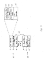
- FIG. 5 is a depiction of the software executed by the processors in the remote director.
- FIG. 6 is another block diagram of the remote director that shows details of a shared memory implementation for exchanging socket interface messages across processor boundaries.
-
- Like reference numerals will be used to represent like elements.
- Referring to FIG. 1, a data processing system 10 includes
host computers controller 16 coupled to pluralities of physical storage devices shown as disk devices 18a,disk devices 18b, ...,disk devices 18k. Each of the disk devices 18 is logically divided, in accordance with known techniques, into one or more logical volumes. - The
controller 16 interconnects the host computers 12 and the disk devices 18. Thecontroller 16 thus receives write commands form the various host computers overbuses appropriate devices 18a, 18b, ..., 18k, over respective connectingbuses buses 20, 22, Thecontroller 16 also receives read requests from the host computers 12 overbuses 20, and delivers requested data to the host computers 12, either from a cache memory of thecontroller 16 or, if the data is not available in cache memory, from the disk devices 18. - In a typical configuration, the
controller 16 also connects to a console PC 24 through a connectingbus 26. The console PC 24 is used for maintenance and access to thecontroller 16 and can be employed to set parameters of thecontroller 16 as is well known in the art. - The controller may be connected to a remote data processing system like the data processing system 10 or a remote data storage system like the data storage system 14 (shown in dashed lines) for data back-up capability by a
data link 28. Thedata link 28 is implemented according to Gigabit Ethernet protocols. Other network protocols can be used as well. Thedata link 28 enables a remote data storage system to store on its own devices a copy of information stored in the devices 18 of the data storage system 14 in a mirrored manner, as will be described. - In operation, the
host computers more host directors 30 over theSCSI bus lines 20. Each host director, in turn, connects over one ormore system buses 32 or 34 to aglobal memory 36. Theglobal memory 36 is preferably a large memory through which thehost director 30 can communicate with the disk devices 18. The global memory includes acommon area 38 for supporting communications between the host computers 12 and the disk devices 18, acache memory 40 for storing data and control data structures, and tables 42 for mapping areas of the disk devices 18 to areas in thecache memory 40. - Also connected to the
global memory 36 are back-end (or disk) directors 44, which control the disk devices 18. In the preferred embodiment, the disk directors are installed in thecontroller 16 in pairs. For simplification, only two disk directors, indicated as disk directors 44a and 44b, are shown. However, it will be understood that additional disk directors may be employed by the system. - Each of the disk directors 44a, 44b supports four bus ports. The disk director 44a connects to two
primary buses secondary buses 22a' and 22b'. The buses are implemented as 16-bit wide SCSI buses. As indicated earlier, other bus protocols besides the SCSI protocol may be used. The twosecondary buses 22a' and 22b' are added for redundancy. Connected to theprimary buses primary buses primary buses disk drive units 18c and 18d. Also connected to theprimary buses secondary buses 22a' and 22b'. When the primary bus is active, its corresponding secondary bus in inactive, and vice versa. The secondary buses of the disk director 44b have been omitted from the figure for purposes of clarity. - Like the
host directors 20, the disk directors 44 are also connected to theglobal memory 36 via one of thesystem buses 32, 34. During a write operation, the disk directors 44 read data stored in theglobal memory 36 by ahost director 30 and write that data to the logical volumes for which they are responsible. During a read operation and in response to a read command, the disk directors 44 read data from a logical volume and write that data to global memory for later delivery by the host director to the requesting host computer 12. - As earlier mentioned, the data storage system 14 can be remotely coupled to another data storage system 14 in a mirrored storage configuration, using the
data link 28. Still referring to FIG. 2, each data storage system 14 in the mirrored storage configuration includes aremote director 48 to connect to thedata link 28 and handle transfers of data over that link. Theremote director 48 communicates with theglobal memory 36 over one of thesystem buses 32, 34. - Referring to FIG. 3, a remote data services (e.g., data mirroring)
storage configuration 50 includes two or more of the data storage systems 14 (illustrated as three data storage systems 14a, 14b and 14c). The data storage systems 14a, 14b and 14c are directly coupled to an IP network (shown as the Internet 52) by respective data links 28a, 28b and 28c. The data links28 are implemented as Gigabit Ethernet transmission channels as mentioned earlier, but any suitable transmission medium for supporting TCP/IP traffic may be used. The data links 28, and theIP network 52, are used to support connections for carrying TCP/IP traffic between the units 14. For example, a first connection 54a may be established between the data storage systems 14a and 14b. A second connection 54b may be established between the data storage systems 14b and 14c. Athird connection 54c may be established between the data storage systems 14c and 14a. In thesystem 50, the data storage systems 14 are configured for remote data mirroring capability. More specifically, in the example shown, there are eight device groups, S1, S2, S3, S4, T1, T2, T3, T4, which are indicated byreference numerals 56a, 56b, 56c, 56d, 56e, 56f, 56g, 56h, respectively. Four of the device groups, S1 through S4, are source device groups, and device groups T1 through T4 are target device groups. In the example shown, the data storage systems 14 are configured in the following manner: the data storage system 14a supports device groups S1, S2 and T3; the data storage system 14b supports device groups S4, T1 and T2; and the data storage system 14c supports the device groups S3 and T4. Thus, the devices in the source group S1 are mirrored in the devices in corresponding target device group T1, devices in the source group S2 are mirrored in the devices in corresponding target device group T2, and so forth. Thus, the units use TCP/IP to exchange storage traffic as required by remote data facility services, for example, the data storage systems 14a and 14b establish a connection with each other so that the data storage system 14a can provide a copy of data residing on the source device group S1 to the target device group T1. Thus, the architecture of the remote directors 48 (as will be described) in the each of the data storage systems 14 allows those systems to use the Internet infrastructure for disaster recovery and other remote data services. Although theIP network 52 is shown as the public Internet, it could instead be a private network. - As shown in FIG. 4, the
remote director 48 includes an RDF director 60 and alink director 62. The RDF director 60 includes aprocessor 64 coupled to a local, nonvolatile memory (NVM) 66. The NVM 66 includes acontrol store 68 and aparameter store 70. Thelink director 62 includes aprocessor 72 coupled to its own,NVM 74, which also includes a control store 76 and aparameter store 78. Thedirectors 60, 62 each have access to a sharedmemory 80. Theprocessor 64 controls the overall operations of theRDF director 62 and communications with thememories 66 and 80. Thecontrol store 68 stores firmware (or microcode) 82 and parameter store stores parameter data, both of which are read each time the data storage system 14 is initialized. Themicrocode 82 is copied into thecontrol store 68 at initialization for subsequent execution by theprocessor 64. Theprocessor 72 controls the overall operations of thelink director 62 and communications with thememories parameter store 78 stores parameter data, both of which are read each time the data storage system 14 is initialized. Themicrocode 84 is copied into the control store 76 at initialization for subsequent execution by theprocessor 72. - Referring to FIG. 5, the
microcodes microcode 82 includes an RDF emulation layer 94, aCommon Device Interface 96 and a firstsocket relay layer 98. Themicrocode 84, executed by thelink processor 72, includes a secondsocket relay layer 100, a TCP/IP layer 102 and anetwork driver 104. Collectively, the socket relays 98, 100 represent asocket interface 108, and pass socket messages to each other. Although theinterface 108 between the higher-level RDF emulation/CDI layers (which execute on the emulation processor 64) and the TCP/IP protocols of layer 102 (which execute on the link processor 74) is shown as being implemented as a socket interface, other interfaces could be used for communications between the RDF emulation and the TCP/IP protocols software. - The RDF emulation 94 can include the following: a system calls layer 110;
advanced functionality modules 112, which may be optional at the director level or even at the data storage system level;common function modules 114, which are provided to each director in thecontroller 16; and an interface (director application) module. Interface modules exist for each of the different types of directors that are available based on connectivity and/or function, for example, a Remote Data Facility (RDF) interface defines the functionality of theremote director 48, mainframe and Open Systems host interfaces, respectively, definehost directors 30, and a back-end interface defines the functionality of the back-end director 44. - The emulation is defined as software that implements both an Upper Level Protocol (ULP), that is, a protocol associated with functionality in one or more of
layers 110, 112 and 114 (from FIG. 5), and functions corresponding to the RDF interface 116. Thus, the emulation 94 resides above any physical transport layers and includes software corresponding to theRDF interface 114 as well as software implementing a ULP. - The
CDI 96 recognizes that different physical transports have different physical formats, data capacities and access characteristics. Consequently, theCDI 96 accommodates and isolates those physical transport differences so that those portions of the drivers and emulations that interact with each other are generic in nature. TheCDI 96 provides for versatility and is intended to support any existing or envisioned transport functionality (or protocol). In addition to abstracting the details of different physical transport protocols, the CDI handles physical data movement (e.g., via a DMA mechanism, as described below) and makes that data movement transparent to emulation software. - The CDI can be viewed as being embodied in an I/O control block (hereinafter, "IOCB") data structure. This IOCB data structure is a generic structure that serves to define a common interface between the emulation 94 and a CDI compliant lower layer (CDI driver) with which the emulation 94 communicates in transferring commands and data. To make a request (containing a ULP command) to a CDI driver, the RDF emulation 94 uses a call, 'CDI IOCTL' that takes as its only parameter a pointer to an IOCB describing the request. During the lifetime of that request and its associated IOCB, the control of the IOCB alternates between the emulation and the CDI driver that has accepted it. The CDI driver has control of the IOCB while an IOCTL call is outstanding. The RDF emulation 94 has control of the IOCB when the call request has been completed. Notification of events, e.g., the completion of an IOCTL call or the arrival of a new ULP command, is signaled by the CDI driver to the emulation by placing corresponding IOCBs on queues referred to herein as event (or completion) queues. Thus, the emulation detects a call request completion status when it determines that the IOCB associated with the call has been placed on an event queue by the CDI driver. By removing the IOCB from the event queue, the emulation gains control of the buffer that had been allocated to that IOCB.
- The
CDI 96 may be supported in a polled or interrupt driven environment. In a polled environment, the emulation must make periodic calls to a routine that acts as an interrupt service routine in that is gives the driver a chance to look at the physical interface and process any accumulated events. This call must be made frequently to facilitate the timely discovery of new events or the completion of requests. In an interrupt driven environment, interrupts allows events to be processed as they occur. - Further architectural and implementation-specific details of the
CDI 96 can be found in co-pending U.S. patent application Ser. No. 09/797,347, filed March 1, 2001, incorporated herein by reference. - Still referring to FIG. 5, below the
CDI 96 is thesocket interface 100. In the described embodiment, the RDF emulation 94 and thesocket interface 100 have knowledge of the CDI format. Thus, theCDI 96 serves to isolate the RDF emulation 94 from the TCP/IP layer. - Implementation-specific details of the TCP/
IP layer 102, as well as lower network layers 104, 106 are implemented in known fashion and therefore described no further herein. It will be appreciated that one skilled in the art would be able to implement the required link processor software (as well as any special hardware assists, e.g., DMA, not shown) necessary to transfer and receive packets over a Gigabit Ethernet data link using TCP/IP. - Although FIG. 5 shows the
link processor firmware 84 as including network (e.g., Gigabit Ethernet) driver and hardware interface software (layers 104, 106), it will be appreciated that one or both of these layers could be implemented in a separate, commercially available Gigabit MAC device or chipset. - Referring to FIG. 6, a conceptual depiction of the
interface 48 that shows some details of the sharedmemory 80 used for passing socket messages between theemulation processor 64 and thelink processor 72 is shown. The sharedmemory 80 includes data structures formessages 120 anddata 122, respectively. The messages are message related to establishing and tearing down individual TCP/IP connections. The data is the data to be encapsulated in a TCP/IP protocol data unit and passed down the protocol stack for processing and transmission over the Gigabit Ethernet data link, or data that was received over the link and decapsulated/processed as it is passed up the protocol stack in known fashion. The message data structures include outgoing and inbound data structures, 120a and 120b, for outgoing and inbound messages, respectively. Likewise, the data structures for managing transfer of data also include an outgoing data structure 122a and an inbound data structure 122b. All of the structures 120a, 120b 122a, 122b may be implemented as the same type of data structure, for example, circular rings. - It will be appreciated that the
director 48 has been implemented as a two-processor architecture for performance reasons, that is, to off load the processing intensive TCP/IP operations from the processor that handles the RDF interface to the link processor. However, a single processor solution is also contemplated. - In addition, while the embodiment described above passes socket messages across the two-processor boundary, it may be possible to split the CDI between processors so that the messages that are passed between processors are CDI messages instead of socket messages. Such an implementation would require that the TCP/IP layer have knowledge of and be coded to conform to the CDI.
- It is to be understood that while the invention has been described in conjunction with the detailed description thereof, the foregoing description is intended to illustrate and not limit the scope of the invention, which is defined by the scope of the appended claims. Other embodiments are within the scope of the following claims.
Claims (10)
- In a remote data mirroring arrangement of data storage systems, a method of operating a data storage system comprises:determining that storage traffic is to be transferred between the data storage system and a remote data storage system to which the data storage system is coupled by an IP network in accordance with a remote data service application; andenabling transfer of the storage traffic between the data storage system and the remote data storage system over the IP network using a native connection to the IP network.
- The method of claim 1, wherein the IP network is the Internet.
- The method of claim 1, wherein the IP network is a private network.
- The method of claim 1, wherein enabling comprises using a socket interface to interface an operation of the remote data service to TCP/IP protocols.
- The method of claim 4, wherein the native connection comprises TCP/IP over Gigabit Ethernet
- The method of claim 5, wherein the socket interface is split across two processors, with a first socket relay residing on a first processor and a second socket relay residing on a second processor.
- The method of claim 6, wherein the first socket relay and remote data service application operation conform to a common interface.
- The method of claim 4, wherein enabling further comprises using the socket interface to create a socket from which the native connection to the IP network is formed.
- A computer program product residing on a computer-readable medium for operating a data storage system in a remote data mirroring arrangement of data storage systems, the computer program product comprising instructions causing a computer to:determine that storage traffic is to be transferred between the data storage system and a remote data storage system to which the data storage system is coupled by an IP network; andenable transfer of the storage traffic between the data storage system and the remote data storage system over the IP network using a native connection to the IP network.
- A data storage system comprising:one or more storage devices;a controller coupled to the one or more storage devices; andwherein the controller directs local storage traffic from the data storage system to a remote data storage system over an IP network using a native connection to the IP network.
Applications Claiming Priority (2)
| Application Number | Priority Date | Filing Date | Title |
|---|---|---|---|
| US32565801P | 2001-09-27 | 2001-09-27 | |
| US325658P | 2001-09-27 |
Publications (1)
| Publication Number | Publication Date |
|---|---|
| EP1298530A1 true EP1298530A1 (en) | 2003-04-02 |
Family
ID=23268836
Family Applications (1)
| Application Number | Title | Priority Date | Filing Date |
|---|---|---|---|
| EP02021471A Ceased EP1298530A1 (en) | 2001-09-27 | 2002-09-25 | Remote data facility over an IP network |
Country Status (3)
| Country | Link |
|---|---|
| US (2) | US6968369B2 (en) |
| EP (1) | EP1298530A1 (en) |
| JP (2) | JP2003263352A (en) |
Cited By (2)
| Publication number | Priority date | Publication date | Assignee | Title |
|---|---|---|---|---|
| US7010650B2 (en) | 2001-11-20 | 2006-03-07 | Hitachi, Ltd. | Multiple data management method, computer and storage device therefor |
| US7751398B1 (en) | 2007-03-28 | 2010-07-06 | Emc Corporation | Techniques for prioritization of messaging traffic |
Families Citing this family (59)
| Publication number | Priority date | Publication date | Assignee | Title |
|---|---|---|---|---|
| US6968369B2 (en) * | 2001-09-27 | 2005-11-22 | Emc Corporation | Remote data facility over an IP network |
| US8065510B2 (en) * | 2007-07-30 | 2011-11-22 | Hewlet-Packard Development Company, L.P. | System and methods of retrieving firmware between network locations |
| US20100228824A1 (en) * | 2009-03-06 | 2010-09-09 | Cisco Technology, Inc. | Distributed server selection for online collaborative computing sessions |
| US8271615B2 (en) | 2009-03-31 | 2012-09-18 | Cloud Connex, Llc | Centrally managing and monitoring software as a service (SaaS) applications |
| US8990453B1 (en) | 2012-12-14 | 2015-03-24 | Emc Corporation | Adaptive and optimized flow control mechanism |
| US9069481B1 (en) * | 2013-06-28 | 2015-06-30 | Emc Corporation | Automated non-disruptive data encapsulation and de-encapsulation |
| US9606870B1 (en) | 2014-03-31 | 2017-03-28 | EMC IP Holding Company LLC | Data reduction techniques in a flash-based key/value cluster storage |
| US9641616B2 (en) | 2014-07-10 | 2017-05-02 | Kabushiki Kaisha Toshiba | Self-steering point-to-point storage protocol |
| CN104601575A (en) * | 2015-01-16 | 2015-05-06 | 网神信息技术(北京)股份有限公司 | One-way safety isolation net gap based data transmission method and system |
| US9880758B1 (en) | 2015-03-30 | 2018-01-30 | EMC IP Holding Company LLC | Data transfer techniques with data replication |
| US9626116B1 (en) | 2015-06-22 | 2017-04-18 | EMC IP Holding Company LLC | Distributed service level objective management in active-active environments |
| US9880946B1 (en) | 2015-06-30 | 2018-01-30 | EMC IP Holdings Company LLC | Data transfer techniques with data replication |
| US9678869B1 (en) | 2015-09-29 | 2017-06-13 | EMC IP Holding Company LLC | Optimized read processing |
| US9933947B1 (en) * | 2015-12-30 | 2018-04-03 | EMC IP Holding Company LLC | Maintaining write consistency on distributed multiple page writes |
| US10409838B1 (en) | 2016-03-18 | 2019-09-10 | EMC IP Holding Company LLC | Managing registration and reservation information in an active-active configuration |
| US10324635B1 (en) | 2016-03-22 | 2019-06-18 | EMC IP Holding Company LLC | Adaptive compression for data replication in a storage system |
| US10565058B1 (en) | 2016-03-30 | 2020-02-18 | EMC IP Holding Company LLC | Adaptive hash-based data replication in a storage system |
| US9971529B1 (en) | 2016-06-30 | 2018-05-15 | EMC IP Holding Company LLC | Selective data replication |
| US10976937B1 (en) | 2016-09-28 | 2021-04-13 | EMC IP Holding Company LLC | Disparate local and remote replication technologies configured for the same device |
| US10503609B1 (en) | 2017-04-27 | 2019-12-10 | EMC IP Holding Company LLC | Replication link smoothing using historical data |
| US10409520B1 (en) | 2017-04-27 | 2019-09-10 | EMC IP Holding Company LLC | Replication of content-based storage using address space slices |
| US10613766B1 (en) | 2017-07-27 | 2020-04-07 | EMC IP Holding Company LLC | Data replication techniques |
| US10645158B1 (en) | 2017-10-10 | 2020-05-05 | EMC IP Holding Company LLC | Host data replication using deduplication and binary search trees |
| US11231867B1 (en) | 2018-01-25 | 2022-01-25 | EMC IP Holding Company LLC | Data replication using deduplication and synchronized hash tables |
| US10303365B1 (en) | 2018-01-31 | 2019-05-28 | EMC IP Holding Company LLC | Data fingerprint distribution on a data storage system |
| US10572172B2 (en) | 2018-04-20 | 2020-02-25 | EMC IP Holding Company LLC | Multi-granular data reduction for remote data replication |
| US10860239B2 (en) | 2018-05-04 | 2020-12-08 | EMC IP Holding Company LLC | Fan-out asynchronous replication caching |
| US11360688B2 (en) | 2018-05-04 | 2022-06-14 | EMC IP Holding Company LLC | Cascading snapshot creation in a native replication 3-site configuration |
| US10705753B2 (en) | 2018-05-04 | 2020-07-07 | EMC IP Holding Company LLC | Fan-out asynchronous replication logical level caching |
| US10853221B2 (en) | 2018-05-04 | 2020-12-01 | EMC IP Holding Company LLC | Performance evaluation and comparison of storage systems |
| US11048722B2 (en) | 2018-07-31 | 2021-06-29 | EMC IP Holding Company LLC | Performance optimization for data persistency in asynchronous replication setups |
| US11210245B2 (en) | 2018-10-09 | 2021-12-28 | EMC IP Holding Company LLC | Data transmission techniques between systems having different communication speeds |
| US10613793B1 (en) | 2018-11-01 | 2020-04-07 | EMC IP Holding Company LLC | Method to support hash based xcopy synchronous replication |
| US10776029B2 (en) | 2018-12-21 | 2020-09-15 | Dell Products, L.P. | System and method for dynamic optimal block size deduplication |
| US11481137B2 (en) | 2019-01-29 | 2022-10-25 | EMC IP Holding Company LLC | Data replication techniques |
| US10719249B1 (en) | 2019-01-31 | 2020-07-21 | EMC IP Holding Company LLC | Extent lock resolution in active/active replication |
| US10853200B2 (en) | 2019-02-01 | 2020-12-01 | EMC IP Holding Company LLC | Consistent input/output (IO) recovery for active/active cluster replication |
| US11194666B2 (en) | 2019-04-26 | 2021-12-07 | EMC IP Holding Company LLC | Time addressable storage in a content addressable storage system |
| US10719257B1 (en) | 2019-04-29 | 2020-07-21 | EMC IP Holding Company LLC | Time-to-live (TTL) license management in an active/active replication session |
| US11157184B2 (en) | 2019-04-30 | 2021-10-26 | EMC IP Holding Company LLC | Host access to storage system metadata |
| US11216388B2 (en) | 2019-04-30 | 2022-01-04 | EMC IP Holding Company LLC | Tiering between storage media in a content aware storage system |
| US10659076B1 (en) | 2019-04-30 | 2020-05-19 | EMC IP Holding Company LLC | Reducing the amount of data stored in a sequence of data blocks by combining deduplication and compression |
| US11301138B2 (en) | 2019-07-19 | 2022-04-12 | EMC IP Holding Company LLC | Dynamic balancing of input/output (IO) operations for a storage system |
| US11238063B2 (en) | 2019-07-25 | 2022-02-01 | EMC IP Holding Company LLC | Provenance-based replication in a storage system |
| US10908828B1 (en) | 2019-07-25 | 2021-02-02 | EMC IP Holding Company LLC | Enhanced quality of service (QoS) for multiple simultaneous replication sessions in a replication setup |
| US11429493B2 (en) | 2020-01-20 | 2022-08-30 | EMC IP Holding Company LLC | Remote rollback of snapshots for asynchronous replication |
| US11461303B2 (en) | 2020-02-06 | 2022-10-04 | EMC IP Holding Company LLC | IO metadata management for directly connected host |
| US11644951B2 (en) | 2020-04-28 | 2023-05-09 | EMC IP Holding Company LLC | Dynamic dashboard of user interface displaying primary object and related objects |
| US11226836B2 (en) | 2020-05-19 | 2022-01-18 | EMC IP Holding Company LLC | Dynamic restructuring of user interface based on usage data |
| US11204713B1 (en) | 2020-05-28 | 2021-12-21 | EMC IP Holding Company LLC | Techniques for selection of a data reduction technique when performing data replication |
| US11455320B2 (en) | 2020-08-31 | 2022-09-27 | EMC IP Holding Company LLC | Automated expansion and reduction of replicated data sets |
| US11593396B2 (en) | 2020-09-23 | 2023-02-28 | EMC IP Holding Company LLC | Smart data offload sync replication |
| US11281407B1 (en) | 2020-09-23 | 2022-03-22 | EMC IP Holding Company LLC | Verified write command in active-active replication |
| US11379144B2 (en) | 2020-09-29 | 2022-07-05 | EMC IP Holding Company LLC | Compliance of replicated data sets |
| US11481138B2 (en) | 2020-09-30 | 2022-10-25 | EMC IP Holding Company LLC | Creating indentical snapshots |
| US11422704B2 (en) | 2020-10-27 | 2022-08-23 | EMC IP Holding Company LLC | Adapting service level policies for external latencies |
| US11893260B2 (en) | 2021-04-22 | 2024-02-06 | EMC IP Holding Company LLC | Snapshot-based remote replication |
| US11755230B2 (en) | 2021-04-22 | 2023-09-12 | EMC IP Holding Company LLC | Asynchronous remote replication of snapshots |
| US11513900B2 (en) | 2021-04-22 | 2022-11-29 | EMC IP Holding Company LLC | Remote replication of snapshots taken while replication was inactive |
Citations (2)
| Publication number | Priority date | Publication date | Assignee | Title |
|---|---|---|---|---|
| US5537533A (en) * | 1994-08-11 | 1996-07-16 | Miralink Corporation | System and method for remote mirroring of digital data from a primary network server to a remote network server |
| WO2001035244A1 (en) * | 1999-11-11 | 2001-05-17 | Miralink Corporation | Flexible remote data mirroring |
Family Cites Families (10)
| Publication number | Priority date | Publication date | Assignee | Title |
|---|---|---|---|---|
| US5544347A (en) * | 1990-09-24 | 1996-08-06 | Emc Corporation | Data storage system controlled remote data mirroring with respectively maintained data indices |
| JP3360138B2 (en) * | 1991-01-17 | 2002-12-24 | 株式会社日立製作所 | Communication control device |
| US5901327A (en) | 1996-05-28 | 1999-05-04 | Emc Corporation | Bundling of write data from channel commands in a command chain for transmission over a data link between data storage systems for remote data mirroring |
| US6324654B1 (en) * | 1998-03-30 | 2001-11-27 | Legato Systems, Inc. | Computer network remote data mirroring system |
| US6658469B1 (en) * | 1998-12-18 | 2003-12-02 | Microsoft Corporation | Method and system for switching between network transport providers |
| AU4707001A (en) * | 1999-11-12 | 2001-06-25 | Crossroads Systems, Inc. | Encapsulation protocol for linking storage area networks over a packet-based network |
| US6938122B2 (en) | 2001-01-23 | 2005-08-30 | Emc Corporation | Remote mirroring in a switched environment |
| US6624388B1 (en) * | 2001-01-25 | 2003-09-23 | The Lincoln Electric Company | System and method providing distributed welding architecture |
| US20030014523A1 (en) * | 2001-07-13 | 2003-01-16 | John Teloh | Storage network data replicator |
| US6968369B2 (en) * | 2001-09-27 | 2005-11-22 | Emc Corporation | Remote data facility over an IP network |
-
2001
- 2001-11-28 US US09/995,464 patent/US6968369B2/en not_active Expired - Lifetime
-
2002
- 2002-09-25 EP EP02021471A patent/EP1298530A1/en not_active Ceased
- 2002-09-27 JP JP2002284213A patent/JP2003263352A/en active Pending
-
2005
- 2005-09-12 US US11/224,408 patent/US7430589B2/en not_active Expired - Lifetime
-
2007
- 2007-03-07 JP JP2007056645A patent/JP4543051B2/en not_active Expired - Lifetime
Patent Citations (2)
| Publication number | Priority date | Publication date | Assignee | Title |
|---|---|---|---|---|
| US5537533A (en) * | 1994-08-11 | 1996-07-16 | Miralink Corporation | System and method for remote mirroring of digital data from a primary network server to a remote network server |
| WO2001035244A1 (en) * | 1999-11-11 | 2001-05-17 | Miralink Corporation | Flexible remote data mirroring |
Non-Patent Citations (1)
| Title |
|---|
| VAN METER R ET AL: "Task force on network storage architecture: Internet-attached storage devices", SYSTEM SCIENCES, 1997, PROCEEDINGS OF THE THIRTIETH HWAII INTERNATIONAL CONFERENCE ON WAILEA, HI, USA 7-10 JAN. 1997, LOS ALAMITOS, CA, USA,IEEE COMPUT. SOC, US, 7 January 1997 (1997-01-07), pages 726, XP010272026, ISBN: 0-8186-7743-0 * |
Cited By (2)
| Publication number | Priority date | Publication date | Assignee | Title |
|---|---|---|---|---|
| US7010650B2 (en) | 2001-11-20 | 2006-03-07 | Hitachi, Ltd. | Multiple data management method, computer and storage device therefor |
| US7751398B1 (en) | 2007-03-28 | 2010-07-06 | Emc Corporation | Techniques for prioritization of messaging traffic |
Also Published As
| Publication number | Publication date |
|---|---|
| US20060031485A1 (en) | 2006-02-09 |
| JP4543051B2 (en) | 2010-09-15 |
| US20030061310A1 (en) | 2003-03-27 |
| US6968369B2 (en) | 2005-11-22 |
| US7430589B2 (en) | 2008-09-30 |
| JP2007282197A (en) | 2007-10-25 |
| JP2003263352A (en) | 2003-09-19 |
Similar Documents
| Publication | Publication Date | Title |
|---|---|---|
| US6968369B2 (en) | Remote data facility over an IP network | |
| US7032228B1 (en) | Common device interface | |
| US6598174B1 (en) | Method and apparatus for storage unit replacement in non-redundant array | |
| US6446141B1 (en) | Storage server system including ranking of data source | |
| US6983303B2 (en) | Storage aggregator for enhancing virtualization in data storage networks | |
| US6553408B1 (en) | Virtual device architecture having memory for storing lists of driver modules | |
| CN100380334C (en) | Remote direct memory access enabled network interface controller switchover and switchback support | |
| US8499025B2 (en) | Apparatus for enhancing performance of a parallel processing environment, and associated methods | |
| JP4733399B2 (en) | Computer system, computer, storage device and management terminal | |
| US6571354B1 (en) | Method and apparatus for storage unit replacement according to array priority | |
| EP1372076B1 (en) | Storage control system and method | |
| US8099471B2 (en) | Method and system for communicating between memory regions | |
| US7634601B1 (en) | Method and apparatus for providing continuous communications between computers | |
| JP4338068B2 (en) | Storage system | |
| EP0709779A2 (en) | Virtual shared disks with application-transparent recovery | |
| US20030204683A1 (en) | Method, system, and storage controller for controlling shared memories | |
| JP2004240949A (en) | Cluster-type storage system and management method thereof | |
| US7484114B2 (en) | Method and apparatus for providing redundant access to a shared resource with a shareable spare adapter | |
| US10552060B1 (en) | Using replication facility to provide secure host network connectivity wherein a first logical device is used exclusively for sending messages from host to second host | |
| US11106605B2 (en) | Enhanced tape drive communication | |
| JP3765198B2 (en) | Computer system | |
| US11163708B2 (en) | Automated transformation from command mode to transport mode | |
| JP5482263B2 (en) | Endpoint sharing system and data transfer method | |
| US20050154984A1 (en) | Interface manager and methods of operation in a storage network | |
| US11595501B2 (en) | Singular control path for mainframe storage |
Legal Events
| Date | Code | Title | Description |
|---|---|---|---|
| PUAI | Public reference made under article 153(3) epc to a published international application that has entered the european phase |
Free format text: ORIGINAL CODE: 0009012 |
|
| 17P | Request for examination filed |
Effective date: 20020925 |
|
| AK | Designated contracting states |
Kind code of ref document: A1 Designated state(s): AT BE BG CH CY CZ DE DK EE ES FI FR GB GR IE IT LI LU MC NL PT SE SK TR Designated state(s): AT BE BG CH CY CZ DE DK EE ES FI FR GB GR IE IT LI LU MC NL PT SE SK TR |
|
| AX | Request for extension of the european patent |
Extension state: AL LT LV MK RO SI |
|
| 17Q | First examination report despatched |
Effective date: 20030627 |
|
| AKX | Designation fees paid |
Designated state(s): DE GB |
|
| APBN | Date of receipt of notice of appeal recorded |
Free format text: ORIGINAL CODE: EPIDOSNNOA2E |
|
| APBR | Date of receipt of statement of grounds of appeal recorded |
Free format text: ORIGINAL CODE: EPIDOSNNOA3E |
|
| APAF | Appeal reference modified |
Free format text: ORIGINAL CODE: EPIDOSCREFNE |
|
| APBT | Appeal procedure closed |
Free format text: ORIGINAL CODE: EPIDOSNNOA9E |
|
| STAA | Information on the status of an ep patent application or granted ep patent |
Free format text: STATUS: THE APPLICATION HAS BEEN REFUSED |
|
| 18R | Application refused |
Effective date: 20100617 |