EP1298384A1 - Automobile optical group module - Google Patents
Automobile optical group module Download PDFInfo
- Publication number
- EP1298384A1 EP1298384A1 EP02380202A EP02380202A EP1298384A1 EP 1298384 A1 EP1298384 A1 EP 1298384A1 EP 02380202 A EP02380202 A EP 02380202A EP 02380202 A EP02380202 A EP 02380202A EP 1298384 A1 EP1298384 A1 EP 1298384A1
- Authority
- EP
- European Patent Office
- Prior art keywords
- casing
- module according
- anterior
- annular cover
- platform
- Prior art date
- Legal status (The legal status is an assumption and is not a legal conclusion. Google has not performed a legal analysis and makes no representation as to the accuracy of the status listed.)
- Granted
Links
- 230000003287 optical effect Effects 0.000 title claims abstract description 29
- 230000007246 mechanism Effects 0.000 claims description 8
- 238000005286 illumination Methods 0.000 claims description 5
- 238000009826 distribution Methods 0.000 claims description 3
- 238000010276 construction Methods 0.000 description 6
- 230000002093 peripheral effect Effects 0.000 description 2
- 230000000694 effects Effects 0.000 description 1
- 230000011664 signaling Effects 0.000 description 1
- 210000002105 tongue Anatomy 0.000 description 1
Images


Classifications
-
- B—PERFORMING OPERATIONS; TRANSPORTING
- B60—VEHICLES IN GENERAL
- B60Q—ARRANGEMENT OF SIGNALLING OR LIGHTING DEVICES, THE MOUNTING OR SUPPORTING THEREOF OR CIRCUITS THEREFOR, FOR VEHICLES IN GENERAL
- B60Q1/00—Arrangement of optical signalling or lighting devices, the mounting or supporting thereof or circuits therefor
- B60Q1/0029—Spatial arrangement
- B60Q1/0041—Spatial arrangement of several lamps in relation to each other
- B60Q1/0052—Spatial arrangement of several lamps in relation to each other concentric
-
- B—PERFORMING OPERATIONS; TRANSPORTING
- B60—VEHICLES IN GENERAL
- B60Q—ARRANGEMENT OF SIGNALLING OR LIGHTING DEVICES, THE MOUNTING OR SUPPORTING THEREOF OR CIRCUITS THEREFOR, FOR VEHICLES IN GENERAL
- B60Q1/00—Arrangement of optical signalling or lighting devices, the mounting or supporting thereof or circuits therefor
- B60Q1/02—Arrangement of optical signalling or lighting devices, the mounting or supporting thereof or circuits therefor the devices being primarily intended to illuminate the way ahead or to illuminate other areas of way or environments
- B60Q1/04—Arrangement of optical signalling or lighting devices, the mounting or supporting thereof or circuits therefor the devices being primarily intended to illuminate the way ahead or to illuminate other areas of way or environments the devices being headlights
- B60Q1/06—Arrangement of optical signalling or lighting devices, the mounting or supporting thereof or circuits therefor the devices being primarily intended to illuminate the way ahead or to illuminate other areas of way or environments the devices being headlights adjustable, e.g. remotely-controlled from inside vehicle
-
- B—PERFORMING OPERATIONS; TRANSPORTING
- B60—VEHICLES IN GENERAL
- B60Q—ARRANGEMENT OF SIGNALLING OR LIGHTING DEVICES, THE MOUNTING OR SUPPORTING THEREOF OR CIRCUITS THEREFOR, FOR VEHICLES IN GENERAL
- B60Q1/00—Arrangement of optical signalling or lighting devices, the mounting or supporting thereof or circuits therefor
- B60Q1/02—Arrangement of optical signalling or lighting devices, the mounting or supporting thereof or circuits therefor the devices being primarily intended to illuminate the way ahead or to illuminate other areas of way or environments
- B60Q1/04—Arrangement of optical signalling or lighting devices, the mounting or supporting thereof or circuits therefor the devices being primarily intended to illuminate the way ahead or to illuminate other areas of way or environments the devices being headlights
- B60Q1/06—Arrangement of optical signalling or lighting devices, the mounting or supporting thereof or circuits therefor the devices being primarily intended to illuminate the way ahead or to illuminate other areas of way or environments the devices being headlights adjustable, e.g. remotely-controlled from inside vehicle
- B60Q1/08—Arrangement of optical signalling or lighting devices, the mounting or supporting thereof or circuits therefor the devices being primarily intended to illuminate the way ahead or to illuminate other areas of way or environments the devices being headlights adjustable, e.g. remotely-controlled from inside vehicle automatically
- B60Q1/10—Arrangement of optical signalling or lighting devices, the mounting or supporting thereof or circuits therefor the devices being primarily intended to illuminate the way ahead or to illuminate other areas of way or environments the devices being headlights adjustable, e.g. remotely-controlled from inside vehicle automatically due to vehicle inclination, e.g. due to load distribution
-
- B—PERFORMING OPERATIONS; TRANSPORTING
- B60—VEHICLES IN GENERAL
- B60Q—ARRANGEMENT OF SIGNALLING OR LIGHTING DEVICES, THE MOUNTING OR SUPPORTING THEREOF OR CIRCUITS THEREFOR, FOR VEHICLES IN GENERAL
- B60Q1/00—Arrangement of optical signalling or lighting devices, the mounting or supporting thereof or circuits therefor
- B60Q1/02—Arrangement of optical signalling or lighting devices, the mounting or supporting thereof or circuits therefor the devices being primarily intended to illuminate the way ahead or to illuminate other areas of way or environments
- B60Q1/04—Arrangement of optical signalling or lighting devices, the mounting or supporting thereof or circuits therefor the devices being primarily intended to illuminate the way ahead or to illuminate other areas of way or environments the devices being headlights
- B60Q1/06—Arrangement of optical signalling or lighting devices, the mounting or supporting thereof or circuits therefor the devices being primarily intended to illuminate the way ahead or to illuminate other areas of way or environments the devices being headlights adjustable, e.g. remotely-controlled from inside vehicle
- B60Q1/08—Arrangement of optical signalling or lighting devices, the mounting or supporting thereof or circuits therefor the devices being primarily intended to illuminate the way ahead or to illuminate other areas of way or environments the devices being headlights adjustable, e.g. remotely-controlled from inside vehicle automatically
- B60Q1/12—Arrangement of optical signalling or lighting devices, the mounting or supporting thereof or circuits therefor the devices being primarily intended to illuminate the way ahead or to illuminate other areas of way or environments the devices being headlights adjustable, e.g. remotely-controlled from inside vehicle automatically due to steering position
-
- F—MECHANICAL ENGINEERING; LIGHTING; HEATING; WEAPONS; BLASTING
- F21—LIGHTING
- F21S—NON-PORTABLE LIGHTING DEVICES; SYSTEMS THEREOF; VEHICLE LIGHTING DEVICES SPECIALLY ADAPTED FOR VEHICLE EXTERIORS
- F21S41/00—Illuminating devices specially adapted for vehicle exteriors, e.g. headlamps
- F21S41/20—Illuminating devices specially adapted for vehicle exteriors, e.g. headlamps characterised by refractors, transparent cover plates, light guides or filters
- F21S41/24—Light guides
-
- F—MECHANICAL ENGINEERING; LIGHTING; HEATING; WEAPONS; BLASTING
- F21—LIGHTING
- F21S—NON-PORTABLE LIGHTING DEVICES; SYSTEMS THEREOF; VEHICLE LIGHTING DEVICES SPECIALLY ADAPTED FOR VEHICLE EXTERIORS
- F21S43/00—Signalling devices specially adapted for vehicle exteriors, e.g. brake lamps, direction indicator lights or reversing lights
- F21S43/10—Signalling devices specially adapted for vehicle exteriors, e.g. brake lamps, direction indicator lights or reversing lights characterised by the light source
- F21S43/13—Signalling devices specially adapted for vehicle exteriors, e.g. brake lamps, direction indicator lights or reversing lights characterised by the light source characterised by the type of light source
- F21S43/14—Light emitting diodes [LED]
-
- F—MECHANICAL ENGINEERING; LIGHTING; HEATING; WEAPONS; BLASTING
- F21—LIGHTING
- F21S—NON-PORTABLE LIGHTING DEVICES; SYSTEMS THEREOF; VEHICLE LIGHTING DEVICES SPECIALLY ADAPTED FOR VEHICLE EXTERIORS
- F21S43/00—Signalling devices specially adapted for vehicle exteriors, e.g. brake lamps, direction indicator lights or reversing lights
- F21S43/20—Signalling devices specially adapted for vehicle exteriors, e.g. brake lamps, direction indicator lights or reversing lights characterised by refractors, transparent cover plates, light guides or filters
- F21S43/235—Light guides
-
- F—MECHANICAL ENGINEERING; LIGHTING; HEATING; WEAPONS; BLASTING
- F21—LIGHTING
- F21Y—INDEXING SCHEME ASSOCIATED WITH SUBCLASSES F21K, F21L, F21S and F21V, RELATING TO THE FORM OR THE KIND OF THE LIGHT SOURCES OR OF THE COLOUR OF THE LIGHT EMITTED
- F21Y2115/00—Light-generating elements of semiconductor light sources
- F21Y2115/10—Light-emitting diodes [LED]
Definitions
- the present invention relates to a module for automobile optical groups, particularly a front module, consisting of a casing bearing the lamp and the various optical elements, such as a reflector or parabola, connection mechanisms, diaphragms, etc., mounted so that it can swivel about a horizontal axis on a platform which can also be turned about a vertical axis.
- a front module consisting of a casing bearing the lamp and the various optical elements, such as a reflector or parabola, connection mechanisms, diaphragms, etc.
- a module of this type is described in Spanish Utility Model application number 200002840 by the applicants.
- This module consists of a casing including the various components and connection mechanisms.
- the casing is mounted so that it can swivel about a horizontal axis on a front cover that is attached to a lower cylindrical platform that can swivel about its vertical axis.
- a gear-based mechanism that allows turning the casing about a horizontal axis.
- the rear cover bears a set of LEDs that are used as optical indicators.
- the object of the present invention is a module for optical groups meant to be mounted inside a headlamp, forming a compact unit that includes the illumination and signalling means as well as all required elements and mechanisms, thereby simplifying the assembly and removal of the unit each time this is necessary and eliminating external elements that could interfere in the assembly of other components of the vehicle.
- the module of the invention consists of an assembly comprised of a casing in which are mounted the reflector or parabola, the lamp, the connection mechanisms, the diaphragm, etc.
- This casing is mounted free to swivel about a horizontal axis on a platform which in turn can swivel about a vertical axis. In this way, the casing and the illumination elements housed in it can be turned about a vertical and a horizontal axis.
- the casing can be mounted as described in the Utility Model 200002840, or by any other system.
- a set of light guides is arranged around the casing of the optical module, running in a longitudinal direction with respect to said casing and mounted between an anterior annular cover through which enter the light guides and a posterior annular cover through which said guides are connected to light sources.
- the anterior and posterior annular covers can be mounted directly on the platform that can swivel about a vertical axis.
- the anterior annular cover is placed in front of the casing, around the output of the light beam, so that it does not interfere with said beam.
- the posterior annular cover is placed behind the casing.
- the light sources may consist of LEDs, while the guides can consist of optic fibres.
- the set of light guides can be connected through the posterior annular cover to two different light sources, with the guides arriving from said light sources being anteriorly connected to two different output groups.
- One of these groups can correspond to the parking lights while the other can be for example correspond to the blinkers.
- the two different output groups of the anterior annular cover can be arranged in concentric annular distributions.
- the light guides can receive the light from LEDs, as mentioned above, or from lamps, which would be placed on the posterior support.
- the light could also arrive from a bundle of fibres that are distributed when reaching the posterior support.
- the anterior and posterior annular covers can also be attached to the module casing, so that the casing and the anterior and posterior annular covers form an assembly that is mounted on the lower platform, which can swivel on a support including a lower arched segment, which follows a circular arc path and runs under the casing parallel to the axis of said casing and that is provided with a toothing that engages a gear wheel of a drive shaft.
- the lower circular arc-shaped segment is crossed peipendicularly by three rollers mounted on the lower cylindrical platform, with two of these rollers being toothed and placed on the toothed side of the aforementioned circular arc shaped lower segment, while the third roller is smooth and rests on the aforementioned lower segment on its side without teeth.
- the lower arched segment that constitutes the support bearing the casing is mounted between the three rollers, which are placed around it on different sides.
- One of the toothed rollers determines the drive shaft.
- the above-described support also has a lens placed in front of the casing, through which passes the light beam.
- the support can consist of two arched segments, a lower one and an upper one that respectively run above and below the casing in a longitudinal sense. Between these two segments is mounted said lens.
- the system for mounting the casing on the lower platform is simplified, as it is achieved by the three rollers that perpendicularly cross the lower arc that determines the support, with one of these arcs further acting as a drive shaft for orientation about a horizontal axis.
- the module of the invention includes the lamp that provides the normal illumination of the vehicle, which is mounted inside the module casing, and also includes the optical indicators defined by the outputs of the light guides through the anterior annular cover, which can act as parking lights, blinkers, etc.
- the lamp can swivel about a vertical axis and a horizontal axis, with the ensuing advantages in positioning and pairing, and allowing combining one or more modules in a single optical group as well as the interchangeability between the left and right side groups.
- the described group provides a novel appearance with a new look, as it has its own design inside the optical group.
- the module of the invention allows the entire mechanism of the optical group to be housed inside it, thereby providing an independent volume inside the group or headlamp.
- the novel aspects of the module of the invention compared to conventional headlamps are: a set of optical guides that transmit light surrounding the casing with the optical components; its looks, as it has an inner design fully independent of the headlamp and that can include in a single assembly all the functions, showing the components of the optical group; the design possibility for the optical group, as the modules are independent; and the possibility of using the same module for both the right side and left side optical groups.
- the optical module casing includes in it the lamp that provides the various illumination functions, the reflector or parabola and the other optical components, such as the diaphragm. On its rear, the casing shall be provided with the power supply cable connection.
- the module of the invention consists of a casing 1 mounted on the platform 2, free to swivel about a horizontal axis 3, figure 2, that can be embodied as described in Utility Model 200002840 or in any other way.
- the platform 2 has a cylindrical configuration and a small height, adopting a disc-like shape with a concave upper surface, and can turn about its vertical axis 4.
- This platform is provided on its perimeter with an axial toothing 5 with which it will engage with a drive gear, not shown in the drawings.
- the casing 1 ends at its rear as a semi-cylindrical surface 6 with the horizontal axis of rotation 3 of the casing.
- This semi-cylindrical surface is provided with an axial toothing 7 which engages a toothed sector 8 mounted on the platform 2 so that it can swivel about an axis 9.
- the toothed sector 8 can cross the platform 2 for connection with a drive element.
- the casing 1 is free to turn about the horizontal axis 3 by actuation of the sector 8, and about the axis 4 by actuation of the platform 2.
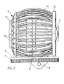
- a set of light guides for example consisting of optic fibres 10, which can be mounted for example between end rings 11 to jointly define a cylindrical cage with a convex generating curve disposed around the casing 1.
- This cage or set of light guides is mounted between an anterior annular cover, labelled in general as 12, and a posterior annular cover labelled 13.
- the two annular covers are mounted on the platform 2, such as by attachment tongues 14 inserted through orifices 15 of the platform 2.
- a set of LEDs 16 each of which constitutes a light source for one of the guides or optic fibres 10.
- said fibres exit through openings that in the example shown in the drawings occupy the two concentric annular distributions 17 and 18, each of which is mounted in a ring, which together for the anterior annular cover 12.
- the set of openings 18 can for example be used as blinkers, while the set of openings 17 can be used for the parking lights.
- the anterior annular cover 12 is disposed around the light output of the casing 1, so that it does not interfere with the outgoing light beam.
- the anterior and posterior annular covers 12 and 13 form a single body with the set of guides or optic fibres 10, which transmit the light induced by the array of LEDs 16.
- the set of LEDs 16 can be replaced by lamps or a bundle of fibres.
- the light guides or optic fibres 10 corresponding to the outputs 17 and 18 can run in alternating positions.
- the casing 1 is mounted on the platform 2 by means of supports including upper arched segments 19 and lower arched segments 20, in the form of a circular arc, that run longitudinally with respect to the casing 1.
- These arched segments are joined on their rear end to the casing 1, while on their front end they are joined to a front ring 21 that bears the lens 22 through which the light beam will exit.
- the lower arched segments 20 of the support are provided with an outer transverse toothing 23 and are transversally crossed by three rollers, an inner smooth roller 24 and two outer toothed rollers 25. These three rollers are mounted on the platform 2, with at least one of the toothed rollers constituting a drive gear for the toothed sectors defined by the lower arched segments 20.
- the casing 1 is mounted on the platform 2 through two rollers 24 and 25, which also act as drive elements for swivelling about the horizontal axis 3.
- the bundle of optic fibres 10 mounted between the anterior annular cover 13 that closes the casing I and a posterior ring 15 that can include an array of LEDs 16, whose light is transmitted through the optic fibres 10 to be visible through the orifices 17 of the annular cover 12.
- the array of LEDs can be replaced by a set of lamps or a bundle of fibres.
- the cover 12 can be attached on casing 1 or positioned on it through the anterior ring 21.
- the lower platform can consist of a disc 17 that is mounted on a ring 18 provided with the peripheral toothing 5.
- the disc 17 is provided with an upper recess through which pass the rollers 11 and 12.
- the casing 1 shall include the connection means 27, the lamp 28, parabola 29, filter 30, etc.
- the casing shall bear on its rear a ring 31 similar to the anterior ring 21, between which pass the arches 19 and 20 that form the casing support.
- a module that supplies the light for the headlamp by means of the lamp or lamps housed in the casing 1, as well as the concentric indication elements provided by the guides or optic fibres 10.
- the module of the invention provides a novel appearance with a new look, as it has its own design inside the optical group.
- the module of the invention allows the entire mechanism of the optical group to be housed inside it, so that an independent volume is provided inside the optical group or headlamp.
- module of the invention compared to conventional headlamps are: a) its looks, as its interior design is fully independent of the headlamp, with the components of the optical group being visible: b) the possibility of design of the optical group, as the modules are independent; c) the possibility of a vertical and horizontal swivelling motion; and d) the possibility of using the same modules and both optical groups on the left and right side.
Landscapes
- Engineering & Computer Science (AREA)
- Mechanical Engineering (AREA)
- General Engineering & Computer Science (AREA)
- Lighting Device Outwards From Vehicle And Optical Signal (AREA)
- Non-Portable Lighting Devices Or Systems Thereof (AREA)
Abstract
Description
- The present invention relates to a module for automobile optical groups, particularly a front module, consisting of a casing bearing the lamp and the various optical elements, such as a reflector or parabola, connection mechanisms, diaphragms, etc., mounted so that it can swivel about a horizontal axis on a platform which can also be turned about a vertical axis.
- A module of this type is described in Spanish Utility Model application number 200002840 by the applicants. This module consists of a casing including the various components and connection mechanisms. The casing is mounted so that it can swivel about a horizontal axis on a front cover that is attached to a lower cylindrical platform that can swivel about its vertical axis. Between the platform and the casing is mounted a gear-based mechanism that allows turning the casing about a horizontal axis. The rear cover bears a set of LEDs that are used as optical indicators.
- The above-described arrangement can result in certain complications in the construction of the module, particularly due to the need to provide an electrical power supply to the set of LEDs set on the front cover.
- The object of the present invention is a module for optical groups meant to be mounted inside a headlamp, forming a compact unit that includes the illumination and signalling means as well as all required elements and mechanisms, thereby simplifying the assembly and removal of the unit each time this is necessary and eliminating external elements that could interfere in the assembly of other components of the vehicle.
- The module of the invention consists of an assembly comprised of a casing in which are mounted the reflector or parabola, the lamp, the connection mechanisms, the diaphragm, etc. This casing is mounted free to swivel about a horizontal axis on a platform which in turn can swivel about a vertical axis. In this way, the casing and the illumination elements housed in it can be turned about a vertical and a horizontal axis.
- In order to enable it to swivel about a horizontal axis the casing can be mounted as described in the Utility Model 200002840, or by any other system.
- In accordance with the present invention, a set of light guides is arranged around the casing of the optical module, running in a longitudinal direction with respect to said casing and mounted between an anterior annular cover through which enter the light guides and a posterior annular cover through which said guides are connected to light sources.
- The anterior and posterior annular covers can be mounted directly on the platform that can swivel about a vertical axis. The anterior annular cover is placed in front of the casing, around the output of the light beam, so that it does not interfere with said beam. On its part, the posterior annular cover is placed behind the casing.
- The light sources may consist of LEDs, while the guides can consist of optic fibres.
- The set of light guides can be connected through the posterior annular cover to two different light sources, with the guides arriving from said light sources being anteriorly connected to two different output groups. One of these groups can correspond to the parking lights while the other can be for example correspond to the blinkers.
- The two different output groups of the anterior annular cover can be arranged in concentric annular distributions.
- The light guides can receive the light from LEDs, as mentioned above, or from lamps, which would be placed on the posterior support. The light could also arrive from a bundle of fibres that are distributed when reaching the posterior support.
- The anterior and posterior annular covers can also be attached to the module casing, so that the casing and the anterior and posterior annular covers form an assembly that is mounted on the lower platform, which can swivel on a support including a lower arched segment, which follows a circular arc path and runs under the casing parallel to the axis of said casing and that is provided with a toothing that engages a gear wheel of a drive shaft.
- Preferably, the lower circular arc-shaped segment is crossed peipendicularly by three rollers mounted on the lower cylindrical platform, with two of these rollers being toothed and placed on the toothed side of the aforementioned circular arc shaped lower segment, while the third roller is smooth and rests on the aforementioned lower segment on its side without teeth.
- With this construction, the lower arched segment that constitutes the support bearing the casing is mounted between the three rollers, which are placed around it on different sides. One of the toothed rollers determines the drive shaft.
- The above-described support also has a lens placed in front of the casing, through which passes the light beam. The support can consist of two arched segments, a lower one and an upper one that respectively run above and below the casing in a longitudinal sense. Between these two segments is mounted said lens.
- According to this embodiment the system for mounting the casing on the lower platform is simplified, as it is achieved by the three rollers that perpendicularly cross the lower arc that determines the support, with one of these arcs further acting as a drive shaft for orientation about a horizontal axis.
- With the described arrangement the module of the invention includes the lamp that provides the normal illumination of the vehicle, which is mounted inside the module casing, and also includes the optical indicators defined by the outputs of the light guides through the anterior annular cover, which can act as parking lights, blinkers, etc. In addition, at least the lamp can swivel about a vertical axis and a horizontal axis, with the ensuing advantages in positioning and pairing, and allowing combining one or more modules in a single optical group as well as the interchangeability between the left and right side groups.
- Furthermore, the described group provides a novel appearance with a new look, as it has its own design inside the optical group. Also, the module of the invention allows the entire mechanism of the optical group to be housed inside it, thereby providing an independent volume inside the group or headlamp.
- The novel aspects of the module of the invention compared to conventional headlamps are: a set of optical guides that transmit light surrounding the casing with the optical components; its looks, as it has an inner design fully independent of the headlamp and that can include in a single assembly all the functions, showing the components of the optical group; the design possibility for the optical group, as the modules are independent; and the possibility of using the same module for both the right side and left side optical groups.
- The optical module casing includes in it the lamp that provides the various illumination functions, the reflector or parabola and the other optical components, such as the diaphragm. On its rear, the casing shall be provided with the power supply cable connection.
- In order to aid a better understanding of the characteristics and advantages of the module of the invention, a more detailed description of it is provided made with the aid of the accompanying drawings of a non-limiting example of an embodiment.
- In the drawings:
- Figure 1 shows a side elevation view of a module for automobile optical groups constructed according to the invention.
- Figure 2 is a front elevation view of the module of figure 1.
- Figure 3 is an exploded perspective view of the module of figures 1 and 2.
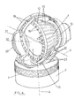
- Figure 4 shows a perspective view of an alternative embodiment for the module of the invention.
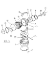
- Figure 5 is an exploded perspective view of the module of figure 4.
-
- As can be best appreciated in figure 3, the module of the invention consists of a
casing 1 mounted on theplatform 2, free to swivel about ahorizontal axis 3, figure 2, that can be embodied as described in Utility Model 200002840 or in any other way. - The
platform 2 has a cylindrical configuration and a small height, adopting a disc-like shape with a concave upper surface, and can turn about itsvertical axis 4. This platform is provided on its perimeter with anaxial toothing 5 with which it will engage with a drive gear, not shown in the drawings. - On its part, the
casing 1 ends at its rear as asemi-cylindrical surface 6 with the horizontal axis ofrotation 3 of the casing. This semi-cylindrical surface is provided with anaxial toothing 7 which engages a toothed sector 8 mounted on theplatform 2 so that it can swivel about an axis 9. The toothed sector 8 can cross theplatform 2 for connection with a drive element. - With the above described construction the
casing 1 is free to turn about thehorizontal axis 3 by actuation of the sector 8, and about theaxis 4 by actuation of theplatform 2. - Around the
casing 1 is provided a set of light guides, for example consisting ofoptic fibres 10, which can be mounted for example betweenend rings 11 to jointly define a cylindrical cage with a convex generating curve disposed around thecasing 1. - This cage or set of light guides is mounted between an anterior annular cover, labelled in general as 12, and a posterior annular cover labelled 13. The two annular covers are mounted on the
platform 2, such as byattachment tongues 14 inserted throughorifices 15 of theplatform 2. - On the posterior
annular cover 13 is mounted a set ofLEDs 16, each of which constitutes a light source for one of the guides oroptic fibres 10. On their opposite end said fibres exit through openings that in the example shown in the drawings occupy the two concentricannular distributions annular cover 12. At each of these openings arrives a different group of guides orfibres 10, which will also be fed by different light sources, such as by two groups of LEDs. The set ofopenings 18 can for example be used as blinkers, while the set ofopenings 17 can be used for the parking lights. - The anterior
annular cover 12 is disposed around the light output of thecasing 1, so that it does not interfere with the outgoing light beam. - The anterior and posterior annular covers 12 and 13 form a single body with the set of guides or
optic fibres 10, which transmit the light induced by the array ofLEDs 16. - As described above, the set of
LEDs 16 can be replaced by lamps or a bundle of fibres. - With the above construction the light guides or
optic fibres 10 corresponding to theoutputs - In the embodiment shown in figures 4 and 5, the
casing 1 is mounted on theplatform 2 by means of supports including upperarched segments 19 and lowerarched segments 20, in the form of a circular arc, that run longitudinally with respect to thecasing 1. These arched segments are joined on their rear end to thecasing 1, while on their front end they are joined to afront ring 21 that bears thelens 22 through which the light beam will exit. - The lower
arched segments 20 of the support are provided with an outertransverse toothing 23 and are transversally crossed by three rollers, an innersmooth roller 24 and twoouter toothed rollers 25. These three rollers are mounted on theplatform 2, with at least one of the toothed rollers constituting a drive gear for the toothed sectors defined by the lowerarched segments 20. - With the above construction, the
casing 1 is mounted on theplatform 2 through tworollers horizontal axis 3. - Placed about the
casing 1 is the bundle ofoptic fibres 10, mounted between the anteriorannular cover 13 that closes the casing I and aposterior ring 15 that can include an array ofLEDs 16, whose light is transmitted through theoptic fibres 10 to be visible through theorifices 17 of theannular cover 12. The array of LEDs can be replaced by a set of lamps or a bundle of fibres. Thecover 12 can be attached oncasing 1 or positioned on it through theanterior ring 21. - When the
platform 2 is actuated through itsperipheral toothing 5 thecasing 1 is made to turn about thevertical axis 4. Actuation of thetoothed rollers 25 effects the swivelling motion of thecasing 1 about thehorizontal axis 3. These toothed rollers can be replaced by toothed segments. - As shown in figure 2, the lower platform can consist of a
disc 17 that is mounted on aring 18 provided with theperipheral toothing 5. Thedisc 17 is provided with an upper recess through which pass therollers - As shown in figure 5, the
casing 1 shall include the connection means 27, thelamp 28,parabola 29,filter 30, etc. In addition the casing shall bear on its rear aring 31 similar to theanterior ring 21, between which pass thearches - With the described construction a module is obtained that supplies the light for the headlamp by means of the lamp or lamps housed in the
casing 1, as well as the concentric indication elements provided by the guides oroptic fibres 10. - The module of the invention provides a novel appearance with a new look, as it has its own design inside the optical group. In addition, the module of the invention allows the entire mechanism of the optical group to be housed inside it, so that an independent volume is provided inside the optical group or headlamp.
- The novel aspects provided by module of the invention compared to conventional headlamps are: a) its looks, as its interior design is fully independent of the headlamp, with the components of the optical group being visible: b) the possibility of design of the optical group, as the modules are independent; c) the possibility of a vertical and horizontal swivelling motion; and d) the possibility of using the same modules and both optical groups on the left and right side.
Claims (10)
- Module for optical groups of automobiles, consisting of a casing (1) bearing the various optical components, such as the reflector or parabola (29), the lamp (28), connection mechanisms (27) and a diaphragm, which casing is mounted so that it can swivel about a horizontal axis (3) on a platform (2) that in turn can swivel about a vertical axis (4), characterised in that around said casing is disposed a set of light guides (10) that run in a longitudinal sense with respect to said casing and that are mounted between an anterior annular cover (12), through which exit the light guides, and a posterior annular cover (13), through which said guides are connected to light sources, with the anterior annular cover placed in front of the casing (1) around the outlet of its light beam, while the posterior annular cover is placed behind said casing.
- Module according to claim 1, characterised in that the anterior (12) and posterior (13) annular covers are mounted directly on the revolving platform (2).
- Module according to claim 1, characterised in that the set of light guides (10) is connected through the posterior annular cover (13) to two different light sources, with the guides that arrive from said light sources exiting on the front through different output groups (17, 18).
- Module according to claim 3, characterised in that the two different output groups of the anterior annular cover are disposed in concentric annular distributions.
- Module according to claim 1, characterised in that the light sources consist of LEDs and the light guides consist of optic fibres.
- Module according to claim 4, characterised in that the optic fibres (10) are mounted between end rings (11) that are attached to the anterior (12) and posterior (13) annular covers to define a cylindrical cage with a convex generating curve.
- Module according to claim 1, characterised in that the anterior (12) and posterior (13) annular covers and the casing (1) bearing the optical components form an assembly that is mounted on the swivelling platform (2) through a support that includes at least one lower arched segment (20), with a circular arc shape, that runs under said casing (1) in a direction parallel to its axis, and is provided with a toothing (23) that engages a gear wheel of a drive shaft (25) mounted on said platform.
- Module according to claim 7, characterised in that the lower segment (20) with a circular arc shape of the support is perpendicularly crossed by three rollers mounted on the aforementioned platform, two of them (25) being toothed and disposed on the toothed side (23) of said lower segment, engaging with it, and the third roller (24) having a smooth surface that rests on said lower segment on the side without toothing.
- Module according to claim 7, characterised in that the support includes two arched segments, a lower one (20) and an upper one (19) that respectively run above and below the casing (1) in a longitudinal sense.
- Module according to claim 7, characterised in that the annular cover for rear illumination (13) includes an annular array of LEDs (16) that is mounted on the rear of the casing (1), from which array runs the set of optic fibres (10) that reaches the anterior annular cover (12), which is provided with orifices through which the end of the optic fibres are visible.
Applications Claiming Priority (4)
| Application Number | Priority Date | Filing Date | Title |
|---|---|---|---|
| ES200102382U ES1050370Y (en) | 2001-09-27 | 2001-09-27 | MODULE FOR OPTICAL GROUPS OF MOTOR VEHICLES. |
| ES200102418 | 2001-10-02 | ||
| ES200102418U ES1050093Y (en) | 2001-10-02 | 2001-10-02 | MODULE FOR OPTICAL FRONT GROUP OF MOTOR VEHICLES. |
| ES200102382 | 2001-10-24 |
Publications (2)
| Publication Number | Publication Date |
|---|---|
| EP1298384A1 true EP1298384A1 (en) | 2003-04-02 |
| EP1298384B1 EP1298384B1 (en) | 2004-03-03 |
Family
ID=26156251
Family Applications (1)
| Application Number | Title | Priority Date | Filing Date |
|---|---|---|---|
| EP02380202A Expired - Lifetime EP1298384B1 (en) | 2001-09-27 | 2002-09-26 | Automobile optical group module |
Country Status (3)
| Country | Link |
|---|---|
| EP (1) | EP1298384B1 (en) |
| AT (1) | ATE261088T1 (en) |
| DE (1) | DE60200244T2 (en) |
Cited By (5)
| Publication number | Priority date | Publication date | Assignee | Title |
|---|---|---|---|---|
| EP1767967A3 (en) * | 2005-09-26 | 2007-05-30 | Osram Sylvania Inc. | Led lamp with direct optical coupling to an optical light guide having purality of light pipes in axial arrangement |
| JP2014075228A (en) * | 2012-10-03 | 2014-04-24 | Koito Mfg Co Ltd | Vehicular lighting fixture |
| CN108692282A (en) * | 2017-08-24 | 2018-10-23 | 常州星宇车灯股份有限公司 | A kind of automobile-used rear combination lamp |
| EP3825602A1 (en) * | 2019-11-20 | 2021-05-26 | Marelli Automotive Lighting Italy S.p.A. | Automotive lighting and/or signaling device |
| KR20220043483A (en) * | 2020-09-29 | 2022-04-05 | 현대자동차주식회사 | Illumination pattern variable apparatus |
Families Citing this family (1)
| Publication number | Priority date | Publication date | Assignee | Title |
|---|---|---|---|---|
| DE102007018698A1 (en) * | 2007-04-18 | 2008-10-23 | Bayerische Motoren Werke Aktiengesellschaft | Vehicle headlight module, has set of LEDs carried by carrier device, and ventilator coupled with carrier device such that cooling air sucked by ventilator flows through cavity of carrier device |
Citations (3)
| Publication number | Priority date | Publication date | Assignee | Title |
|---|---|---|---|---|
| US4631642A (en) * | 1984-05-25 | 1986-12-23 | Cibie Projecteurs | Adaptor for coupling a light guide to a light source, in particular for providing an integrated side light in a motor vehicle headlamp assembly |
| DE19838224A1 (en) * | 1998-08-22 | 2000-02-24 | Daimler Chrysler Ag | Front lamp arrangement for cars has additional lamp devices with optic fibre element conducting light from entry side to exit side around periphery of headlamp unit |
| ES1047668U (en) * | 2000-11-21 | 2001-05-01 | Seat Sa | Module for headlights of motor vehicles. (Machine-translation by Google Translate, not legally binding) |
-
2002
- 2002-09-26 EP EP02380202A patent/EP1298384B1/en not_active Expired - Lifetime
- 2002-09-26 AT AT02380202T patent/ATE261088T1/en not_active IP Right Cessation
- 2002-09-26 DE DE60200244T patent/DE60200244T2/en not_active Expired - Lifetime
Patent Citations (3)
| Publication number | Priority date | Publication date | Assignee | Title |
|---|---|---|---|---|
| US4631642A (en) * | 1984-05-25 | 1986-12-23 | Cibie Projecteurs | Adaptor for coupling a light guide to a light source, in particular for providing an integrated side light in a motor vehicle headlamp assembly |
| DE19838224A1 (en) * | 1998-08-22 | 2000-02-24 | Daimler Chrysler Ag | Front lamp arrangement for cars has additional lamp devices with optic fibre element conducting light from entry side to exit side around periphery of headlamp unit |
| ES1047668U (en) * | 2000-11-21 | 2001-05-01 | Seat Sa | Module for headlights of motor vehicles. (Machine-translation by Google Translate, not legally binding) |
Cited By (5)
| Publication number | Priority date | Publication date | Assignee | Title |
|---|---|---|---|---|
| EP1767967A3 (en) * | 2005-09-26 | 2007-05-30 | Osram Sylvania Inc. | Led lamp with direct optical coupling to an optical light guide having purality of light pipes in axial arrangement |
| JP2014075228A (en) * | 2012-10-03 | 2014-04-24 | Koito Mfg Co Ltd | Vehicular lighting fixture |
| CN108692282A (en) * | 2017-08-24 | 2018-10-23 | 常州星宇车灯股份有限公司 | A kind of automobile-used rear combination lamp |
| EP3825602A1 (en) * | 2019-11-20 | 2021-05-26 | Marelli Automotive Lighting Italy S.p.A. | Automotive lighting and/or signaling device |
| KR20220043483A (en) * | 2020-09-29 | 2022-04-05 | 현대자동차주식회사 | Illumination pattern variable apparatus |
Also Published As
| Publication number | Publication date |
|---|---|
| DE60200244T2 (en) | 2005-03-03 |
| ATE261088T1 (en) | 2004-03-15 |
| EP1298384B1 (en) | 2004-03-03 |
| DE60200244D1 (en) | 2004-04-08 |
Similar Documents
| Publication | Publication Date | Title |
|---|---|---|
| US6910791B2 (en) | Headlight | |
| US5884997A (en) | Light bar | |
| US5647657A (en) | Light system for an interior of a motor vehicle | |
| US4357595A (en) | Flashing light warning system for vehicles | |
| EP0122683B1 (en) | Vehicle lamp assembly | |
| EP0071558B1 (en) | Combined flood and spot light | |
| JP2003151318A (en) | Elliptical headlamp with sub-optical system | |
| EP1298384B1 (en) | Automobile optical group module | |
| US4240062A (en) | Flashing light warning system for vehicles | |
| EP0869312A2 (en) | Vehicle signal lamp | |
| TWI521164B (en) | Vehicle headlight construction | |
| US1262394A (en) | Vehicle-lamp. | |
| HK5392A (en) | Lamp with light collecting reflector | |
| US5347438A (en) | Combined illumination and safety lamp | |
| CZ296081B6 (en) | Compact structure of motor vehicle LED lamp | |
| US3287551A (en) | Fog lights | |
| ES2139163T3 (en) | REAR LIGHTS OF AN AUTOMOBILE VEHICLE. | |
| US20050036333A1 (en) | Lamp assembly with peripheral auxiliary function | |
| US3892960A (en) | Light projector fittings | |
| CN108775549B (en) | Lighting device for vehicle with rotary lighting module | |
| US3514752A (en) | Compact traffic signal | |
| US7147354B2 (en) | Interior illumination lamp | |
| EP0886101A2 (en) | Lamp for motor-vehicles | |
| JPH04289602A (en) | Sun visor with walking lighting | |
| EP3354968B1 (en) | Lighting module and lighting device for vehicles having welcome function |
Legal Events
| Date | Code | Title | Description |
|---|---|---|---|
| PUAI | Public reference made under article 153(3) epc to a published international application that has entered the european phase |
Free format text: ORIGINAL CODE: 0009012 |
|
| AK | Designated contracting states |
Kind code of ref document: A1 Designated state(s): AT BE BG CH CY CZ DE DK EE ES FI FR GB GR IE IT LI LU MC NL PT SE SK TR |
|
| AX | Request for extension of the european patent |
Extension state: AL LT LV MK RO SI |
|
| 17P | Request for examination filed |
Effective date: 20030404 |
|
| GRAH | Despatch of communication of intention to grant a patent |
Free format text: ORIGINAL CODE: EPIDOS IGRA |
|
| GRAS | Grant fee paid |
Free format text: ORIGINAL CODE: EPIDOSNIGR3 |
|
| AKX | Designation fees paid |
Designated state(s): AT BE BG CH CY CZ DE DK EE ES FI FR GB GR IE IT LI LU MC NL PT SE SK TR |
|
| GRAA | (expected) grant |
Free format text: ORIGINAL CODE: 0009210 |
|
| AK | Designated contracting states |
Kind code of ref document: B1 Designated state(s): AT BE BG CH CY CZ DE DK EE ES FI FR GB GR IE IT LI LU MC NL PT SE SK TR |
|
| PG25 | Lapsed in a contracting state [announced via postgrant information from national office to epo] |
Ref country code: FI Free format text: LAPSE BECAUSE OF FAILURE TO SUBMIT A TRANSLATION OF THE DESCRIPTION OR TO PAY THE FEE WITHIN THE PRESCRIBED TIME-LIMIT Effective date: 20040303 Ref country code: NL Free format text: LAPSE BECAUSE OF FAILURE TO SUBMIT A TRANSLATION OF THE DESCRIPTION OR TO PAY THE FEE WITHIN THE PRESCRIBED TIME-LIMIT Effective date: 20040303 Ref country code: BE Free format text: LAPSE BECAUSE OF FAILURE TO SUBMIT A TRANSLATION OF THE DESCRIPTION OR TO PAY THE FEE WITHIN THE PRESCRIBED TIME-LIMIT Effective date: 20040303 Ref country code: TR Free format text: LAPSE BECAUSE OF FAILURE TO SUBMIT A TRANSLATION OF THE DESCRIPTION OR TO PAY THE FEE WITHIN THE PRESCRIBED TIME-LIMIT Effective date: 20040303 Ref country code: CH Free format text: LAPSE BECAUSE OF FAILURE TO SUBMIT A TRANSLATION OF THE DESCRIPTION OR TO PAY THE FEE WITHIN THE PRESCRIBED TIME-LIMIT Effective date: 20040303 Ref country code: BG Free format text: LAPSE BECAUSE OF FAILURE TO SUBMIT A TRANSLATION OF THE DESCRIPTION OR TO PAY THE FEE WITHIN THE PRESCRIBED TIME-LIMIT Effective date: 20040303 Ref country code: CZ Free format text: LAPSE BECAUSE OF FAILURE TO SUBMIT A TRANSLATION OF THE DESCRIPTION OR TO PAY THE FEE WITHIN THE PRESCRIBED TIME-LIMIT Effective date: 20040303 Ref country code: SK Free format text: LAPSE BECAUSE OF FAILURE TO SUBMIT A TRANSLATION OF THE DESCRIPTION OR TO PAY THE FEE WITHIN THE PRESCRIBED TIME-LIMIT Effective date: 20040303 Ref country code: LI Free format text: LAPSE BECAUSE OF FAILURE TO SUBMIT A TRANSLATION OF THE DESCRIPTION OR TO PAY THE FEE WITHIN THE PRESCRIBED TIME-LIMIT Effective date: 20040303 Ref country code: CY Free format text: LAPSE BECAUSE OF FAILURE TO SUBMIT A TRANSLATION OF THE DESCRIPTION OR TO PAY THE FEE WITHIN THE PRESCRIBED TIME-LIMIT Effective date: 20040303 Ref country code: AT Free format text: LAPSE BECAUSE OF FAILURE TO SUBMIT A TRANSLATION OF THE DESCRIPTION OR TO PAY THE FEE WITHIN THE PRESCRIBED TIME-LIMIT Effective date: 20040303 Ref country code: EE Free format text: LAPSE BECAUSE OF FAILURE TO SUBMIT A TRANSLATION OF THE DESCRIPTION OR TO PAY THE FEE WITHIN THE PRESCRIBED TIME-LIMIT Effective date: 20040303 |
|
| REG | Reference to a national code |
Ref country code: GB Ref legal event code: FG4D |
|
| REG | Reference to a national code |
Ref country code: CH Ref legal event code: EP |
|
| REG | Reference to a national code |
Ref country code: IE Ref legal event code: FG4D |
|
| REF | Corresponds to: |
Ref document number: 60200244 Country of ref document: DE Date of ref document: 20040408 Kind code of ref document: P |
|
| PG25 | Lapsed in a contracting state [announced via postgrant information from national office to epo] |
Ref country code: GR Free format text: LAPSE BECAUSE OF FAILURE TO SUBMIT A TRANSLATION OF THE DESCRIPTION OR TO PAY THE FEE WITHIN THE PRESCRIBED TIME-LIMIT Effective date: 20040603 Ref country code: DK Free format text: LAPSE BECAUSE OF FAILURE TO SUBMIT A TRANSLATION OF THE DESCRIPTION OR TO PAY THE FEE WITHIN THE PRESCRIBED TIME-LIMIT Effective date: 20040603 Ref country code: SE Free format text: LAPSE BECAUSE OF FAILURE TO SUBMIT A TRANSLATION OF THE DESCRIPTION OR TO PAY THE FEE WITHIN THE PRESCRIBED TIME-LIMIT Effective date: 20040603 |
|
| PG25 | Lapsed in a contracting state [announced via postgrant information from national office to epo] |
Ref country code: ES Free format text: LAPSE BECAUSE OF FAILURE TO SUBMIT A TRANSLATION OF THE DESCRIPTION OR TO PAY THE FEE WITHIN THE PRESCRIBED TIME-LIMIT Effective date: 20040614 |
|
| NLV1 | Nl: lapsed or annulled due to failure to fulfill the requirements of art. 29p and 29m of the patents act | ||
| REG | Reference to a national code |
Ref country code: CH Ref legal event code: PL |
|
| PG25 | Lapsed in a contracting state [announced via postgrant information from national office to epo] |
Ref country code: LU Free format text: LAPSE BECAUSE OF NON-PAYMENT OF DUE FEES Effective date: 20040926 |
|
| PG25 | Lapsed in a contracting state [announced via postgrant information from national office to epo] |
Ref country code: IE Free format text: LAPSE BECAUSE OF NON-PAYMENT OF DUE FEES Effective date: 20040927 |
|
| PG25 | Lapsed in a contracting state [announced via postgrant information from national office to epo] |
Ref country code: MC Free format text: LAPSE BECAUSE OF NON-PAYMENT OF DUE FEES Effective date: 20040930 |
|
| ET | Fr: translation filed | ||
| PLBE | No opposition filed within time limit |
Free format text: ORIGINAL CODE: 0009261 |
|
| STAA | Information on the status of an ep patent application or granted ep patent |
Free format text: STATUS: NO OPPOSITION FILED WITHIN TIME LIMIT |
|
| 26N | No opposition filed |
Effective date: 20041206 |
|
| REG | Reference to a national code |
Ref country code: IE Ref legal event code: MM4A |
|
| PG25 | Lapsed in a contracting state [announced via postgrant information from national office to epo] |
Ref country code: PT Free format text: LAPSE BECAUSE OF NON-PAYMENT OF DUE FEES Effective date: 20040803 |
|
| PGFP | Annual fee paid to national office [announced via postgrant information from national office to epo] |
Ref country code: FR Payment date: 20100903 Year of fee payment: 9 |
|
| PGFP | Annual fee paid to national office [announced via postgrant information from national office to epo] |
Ref country code: GB Payment date: 20100902 Year of fee payment: 9 |
|
| PGFP | Annual fee paid to national office [announced via postgrant information from national office to epo] |
Ref country code: DE Payment date: 20100928 Year of fee payment: 9 |
|
| PGFP | Annual fee paid to national office [announced via postgrant information from national office to epo] |
Ref country code: IT Payment date: 20100923 Year of fee payment: 9 |
|
| GBPC | Gb: european patent ceased through non-payment of renewal fee |
Effective date: 20110926 |
|
| PG25 | Lapsed in a contracting state [announced via postgrant information from national office to epo] |
Ref country code: IT Free format text: LAPSE BECAUSE OF NON-PAYMENT OF DUE FEES Effective date: 20110926 |
|
| REG | Reference to a national code |
Ref country code: FR Ref legal event code: ST Effective date: 20120531 |
|
| REG | Reference to a national code |
Ref country code: DE Ref legal event code: R119 Ref document number: 60200244 Country of ref document: DE Effective date: 20120403 |
|
| PG25 | Lapsed in a contracting state [announced via postgrant information from national office to epo] |
Ref country code: DE Free format text: LAPSE BECAUSE OF NON-PAYMENT OF DUE FEES Effective date: 20120403 |
|
| PG25 | Lapsed in a contracting state [announced via postgrant information from national office to epo] |
Ref country code: GB Free format text: LAPSE BECAUSE OF NON-PAYMENT OF DUE FEES Effective date: 20110926 Ref country code: FR Free format text: LAPSE BECAUSE OF NON-PAYMENT OF DUE FEES Effective date: 20110930 |