EP1298325A2 - Pump control system - Google Patents
Pump control system Download PDFInfo
- Publication number
- EP1298325A2 EP1298325A2 EP02014931A EP02014931A EP1298325A2 EP 1298325 A2 EP1298325 A2 EP 1298325A2 EP 02014931 A EP02014931 A EP 02014931A EP 02014931 A EP02014931 A EP 02014931A EP 1298325 A2 EP1298325 A2 EP 1298325A2
- Authority
- EP
- European Patent Office
- Prior art keywords
- supply
- control system
- pump control
- header
- pump
- Prior art date
- Legal status (The legal status is an assumption and is not a legal conclusion. Google has not performed a legal analysis and makes no representation as to the accuracy of the status listed.)
- Granted
Links
Images



Classifications
-
- F—MECHANICAL ENGINEERING; LIGHTING; HEATING; WEAPONS; BLASTING
- F04—POSITIVE - DISPLACEMENT MACHINES FOR LIQUIDS; PUMPS FOR LIQUIDS OR ELASTIC FLUIDS
- F04D—NON-POSITIVE-DISPLACEMENT PUMPS
- F04D15/00—Control, e.g. regulation, of pumps, pumping installations or systems
- F04D15/02—Stopping of pumps, or operating valves, on occurrence of unwanted conditions
- F04D15/0209—Stopping of pumps, or operating valves, on occurrence of unwanted conditions responsive to a condition of the working fluid
-
- F—MECHANICAL ENGINEERING; LIGHTING; HEATING; WEAPONS; BLASTING
- F04—POSITIVE - DISPLACEMENT MACHINES FOR LIQUIDS; PUMPS FOR LIQUIDS OR ELASTIC FLUIDS
- F04B—POSITIVE-DISPLACEMENT MACHINES FOR LIQUIDS; PUMPS
- F04B49/00—Control, e.g. of pump delivery, or pump pressure of, or safety measures for, machines, pumps, or pumping installations, not otherwise provided for, or of interest apart from, groups F04B1/00 - F04B47/00
- F04B49/06—Control using electricity
- F04B49/065—Control using electricity and making use of computers
-
- F—MECHANICAL ENGINEERING; LIGHTING; HEATING; WEAPONS; BLASTING
- F04—POSITIVE - DISPLACEMENT MACHINES FOR LIQUIDS; PUMPS FOR LIQUIDS OR ELASTIC FLUIDS
- F04D—NON-POSITIVE-DISPLACEMENT PUMPS
- F04D13/00—Pumping installations or systems
- F04D13/12—Combinations of two or more pumps
- F04D13/14—Combinations of two or more pumps the pumps being all of centrifugal type
-
- F—MECHANICAL ENGINEERING; LIGHTING; HEATING; WEAPONS; BLASTING
- F04—POSITIVE - DISPLACEMENT MACHINES FOR LIQUIDS; PUMPS FOR LIQUIDS OR ELASTIC FLUIDS
- F04D—NON-POSITIVE-DISPLACEMENT PUMPS
- F04D15/00—Control, e.g. regulation, of pumps, pumping installations or systems
- F04D15/0066—Control, e.g. regulation, of pumps, pumping installations or systems by changing the speed, e.g. of the driving engine
-
- F—MECHANICAL ENGINEERING; LIGHTING; HEATING; WEAPONS; BLASTING
- F04—POSITIVE - DISPLACEMENT MACHINES FOR LIQUIDS; PUMPS FOR LIQUIDS OR ELASTIC FLUIDS
- F04D—NON-POSITIVE-DISPLACEMENT PUMPS
- F04D15/00—Control, e.g. regulation, of pumps, pumping installations or systems
- F04D15/02—Stopping of pumps, or operating valves, on occurrence of unwanted conditions
- F04D15/029—Stopping of pumps, or operating valves, on occurrence of unwanted conditions for pumps operating in parallel
-
- F—MECHANICAL ENGINEERING; LIGHTING; HEATING; WEAPONS; BLASTING
- F04—POSITIVE - DISPLACEMENT MACHINES FOR LIQUIDS; PUMPS FOR LIQUIDS OR ELASTIC FLUIDS
- F04B—POSITIVE-DISPLACEMENT MACHINES FOR LIQUIDS; PUMPS
- F04B2203/00—Motor parameters
- F04B2203/02—Motor parameters of rotating electric motors
- F04B2203/0214—Number of working motor-pump units
-
- F—MECHANICAL ENGINEERING; LIGHTING; HEATING; WEAPONS; BLASTING
- F04—POSITIVE - DISPLACEMENT MACHINES FOR LIQUIDS; PUMPS FOR LIQUIDS OR ELASTIC FLUIDS
- F04B—POSITIVE-DISPLACEMENT MACHINES FOR LIQUIDS; PUMPS
- F04B2205/00—Fluid parameters
- F04B2205/09—Flow through the pump
-
- F—MECHANICAL ENGINEERING; LIGHTING; HEATING; WEAPONS; BLASTING
- F25—REFRIGERATION OR COOLING; COMBINED HEATING AND REFRIGERATION SYSTEMS; HEAT PUMP SYSTEMS; MANUFACTURE OR STORAGE OF ICE; LIQUEFACTION SOLIDIFICATION OF GASES
- F25B—REFRIGERATION MACHINES, PLANTS OR SYSTEMS; COMBINED HEATING AND REFRIGERATION SYSTEMS; HEAT PUMP SYSTEMS
- F25B2600/00—Control issues
- F25B2600/13—Pump speed control
-
- Y—GENERAL TAGGING OF NEW TECHNOLOGICAL DEVELOPMENTS; GENERAL TAGGING OF CROSS-SECTIONAL TECHNOLOGIES SPANNING OVER SEVERAL SECTIONS OF THE IPC; TECHNICAL SUBJECTS COVERED BY FORMER USPC CROSS-REFERENCE ART COLLECTIONS [XRACs] AND DIGESTS
- Y02—TECHNOLOGIES OR APPLICATIONS FOR MITIGATION OR ADAPTATION AGAINST CLIMATE CHANGE
- Y02B—CLIMATE CHANGE MITIGATION TECHNOLOGIES RELATED TO BUILDINGS, e.g. HOUSING, HOUSE APPLIANCES OR RELATED END-USER APPLICATIONS
- Y02B30/00—Energy efficient heating, ventilation or air conditioning [HVAC]
- Y02B30/70—Efficient control or regulation technologies, e.g. for control of refrigerant flow, motor or heating
Definitions
- the present invention relates to a pump control system that has an electric energy-saving effect, used for pressurized water pump systems, air-conditioning systems, and the like.
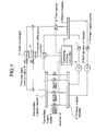
- Fig. 1 is a drawing illustrating the configuration of an example of conventional pump control system generally used from the past, in which a pump control system is used for pressurized water pump system.
- primary supply pumps 1 supply chilled water or hot water from return header 2 to primary supply header 4 via refrigerators or heat pump chillers or boilers 3.
- Secondary supply pumps 5 are provided with inverters 6 and supply chilled water or hot water to secondary supply header 7 from primary supply header 4.
- Flow sensor 8 measures the flow rate of chilled water or hot water supplied to return header 2 via two-way type control valves 9 and heat exchangers 11 from secondary supply header 7.
- Pressure difference sensor 12 measures the differential pressure of chilled water or hot water between secondary supply header 7 and return header 2.
- Controller for controlling the number of operating pumps 13 issues operation commands to secondary supply pumps 5 so that the optimum number of operating pumps is obtained using values measured by flow sensor 8 and pressure difference sensor 12.
- chilled water or hot water delivered from primary supply pumps 1 is supplied to heat exchangers 11 at the secondary use point by secondary supply pumps 5.
- the flow rate of the secondary circulating flow is variable because two-way type control valves 9 are controlled depending on the heat exchanging amounts required by heat exchangers 11.
- controller for controlling the number of operating pumps 13 issues operation commands to secondary supply pumps 5 so that the optimum number of operating pumps is obtained by detecting flow rate with flow sensor 8, and at the same time sends a rotational frequency control signal to inverters 6 so that the required pre-set differential pressure is obtained by detecting the differential pressure between secondary supply header 7 and return header 2 with pressure difference sensor 12.
- the present invention is intended to overcome the above-mentioned problems and to provide a pump control system having an electric power-saving effect.
- FIG. 2 is a drawing illustrating an essential part of the configuration of a pump control system in an embodiment of the present invention.
- Fig. 3 and Fig. 4 are drawings illustrating operations of the system shown in Fig. 2. This embodiment is for a pump control system used for a pressurized water pump system.
- Controller for controlling the number of operating pumps 21 issues operation commands to secondary supply pumps 5 so that the optimum number of operating pumps is obtained using the value measured with flow sensor 8.
- Secondary pump controller 22 contains input-output processing portion 221 that determines the rotational frequency (revolution) of inverters 6 by selecting numerical values of fixed resistance K0 of the entire system, pipeline constants K1 and K2, and constant n using the formula of head of friction loss based on external input signal 31, and by calculating supply pressure P1 from these values and a signal measured with flow sensor 8.
- Monitor signal input portion 23 inputs monitor input signals to input-output processing portion 221.
- Operation display portion 222 provided in secondary pump controller 22, displays the operating status.
- Secondary external communication portion 224 provided in secondary pump controller 22, changes the settings of parameters necessary for operation from a remote place via remote communication means 24.
- the Internet is utilized as remote communication means 24.
- the data storage portion provided in secondary pump controller 22, stores various data.
- External operation terminal 25 is connected to secondary pump controller 22 through remote communication means 24.
- Signal conditioner 26 carries out conversion of external input signal 31.
- Control of the number of operating secondary supply pumps 5 is performed by controller for controlling the number of operating pumps 21. Rotational frequency control of secondary supply pumps 5 is performed as described below.
- input-output processing portion 221 Based on supply pressure value P1 from secondary supply pumps determined by equation (1) and the discharge pressure measured with pressure difference sensor 12, input-output processing portion 221 carries out PID operation and outputs a rotational frequency control signal to inverters 6.
- Parameters should be selected based on external input signal 31, for example, outside air temperature input signal or production equipment power consumption input signal, or from various tables stored in data storage portion 225, e.g., seasonal change table, availability factor change table, or load change table.
- the rotational frequency control signal is output to inverters 6 by selecting optimum parameters (K0, K1, K2, and n) and performing calculations in input-output processing portion 221.
- the rotational frequency control signal is output to inverters 6 by changing the settings for fixed resistance K0 for the entire system, pipeline constants K1 and K2, and the constant n based on the formula of head of friction loss (normally 2), input from operation display portion 222, in input-output processing portion 221 to obtain optimum values, based on external input signal 31 (outside air temperature, seasonal changes, availability factor changes, and load changes).
- pattern 1, pattern 2, pattern 3, pattern 4, etc. are determined in advance corresponding to the combination of numerical values of K0, K1, K2, and n.
- K0, K1, K2, and n are determined by dividing the seasonal changes into spring, summer, autumn, and winter as shown below.
- the setup of prescribed constant pressure or prescribed constant frequency and prescribed time is input at operation display portion 222 at the start of operation of secondary supply pumps 5.
- a prescribed constant pressure #.## MPa is applied for a prescribed time ## minutes from the start of operation of secondary supply pumps 5. That is, the discharge pressure P of secondary supply pumps 5 is set to constant Pc only for the prescribed time from the start of operation.
- startup operation of a pressurized water pump system can be established earlier.
- supply pressure P1 from the secondary supply pumps is expressed as shown below as described above.
- P1 K0 + K1 ⁇ Q + K2 ⁇ Q n
- the result of calculation using the input Q and set parameters K0, K1, K2, and n is P1 and thus if parameters K0, K1, K2, and n are set too low, the system may stabilize at a low flow rate.
- the rotational frequency of above-mentioned inverters is determined so that a prescribed amount is added to the value of supply pressure P1 calculated in input-output processing portion 221 for a prescribed period at every prescribed time interval.
- a prescribed pressure #.## MPa to be increased is added for a prescribed period ## minutes at every prescribed time interval ### minutes. That is, the value of supply pressure P1 from the secondary supply pumps is raised only for a certain period at every certain time interval.
- the setup of a pressure or frequency to be raised and prescribed period and interval is input at operation display portion 222.
- monitor signal input portion 23 inputs a monitor input signal to input-output processing portion 221 and stores data in data storage portion 225, as well as makes operation display portion 222 display a trend-graph and numerical values.
- the monitor input signal and various parameter values are monitored in external operation terminal 25 located in a remote place after passing through remote communication means 24 from primary and secondary external communication portions 223 and 224, and at the same time external operation terminal 25 changes the settings for the values to be set.
- cost calculation for the energy-saving effect can also be done in external operation terminal 25.
- the means is not restricted to this but, for example, telephone lines can also be directly used.
- any communication means can be used provided it can send signals to remote places.
- Fig. 5 is a drawing illustrating an essential part of the configuration of a pump control system in another embodiment of the present invention.
- FIG. 6, Fig. 7 and Fig. 8 are drawings respectively illustrating operations of the invention shown in Fig. 5.
- This embodiment shows a pump control system used for an air-conditioning system.
- Secondary pump controller 30 contains input-output processing portion 221 that controls the rotational frequency of inverters 6 using the signal for two-way type control valves 9 opening and the value measured by pressure difference sensor 12.
- Signal conditioner 261 converts the signal to be given to two-way type control valves 9.
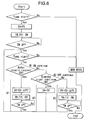
- Fig. 6 indicates a flow chart
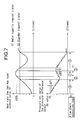
- Fig. 7 indicates the relationship between water supply request signal S1, standby request signal S2, open rate V1 of the two-way type control valves 9, pressure set value P of the pressure difference sensor 12, and the flow chart shown in Fig. 6.
- #1 indicates a supply water flow increasing loop
- #2 indicates a constant supply water flow loop
- #3 a supply water flow decreasing loop.
- the vertical axes indicate the open rate V1 of two-way type control valves 9 and the pressure set value P of pressure difference sensor 12 respectively and the horizontal axes indicate time t1 and t2 respectively.
- Operation is started at the initial value PS of pressure set value SV at the startup of secondary supply pumps 5.
- PID operation is carried out in input-output processing portion 221 using the difference between this pressure set value SV and the differential pressure signal from pressure difference sensor 12, and the rotational frequency control signal for inverters 6 is output.
- the monitor input signal is input from monitor signal input portion 23, data are stored in the data memory portion and at the same time trend-graphs and numerical values, etc. are indicated in the monitor display portion.
- the monitor input signal and various parameter values are monitored in external operation terminal 25 located in a remote place after passing through remote communication means 24 from the primary and secondary external communication portions, and at the same time external operation terminal 25 changes the settings for the values to be set.
- an example of conventional systems shown in Fig. 1 employs control at constant differential pressure and the operating point moves as shown by a, b, c, « .
- G1 shows the head curve of secondary supply pumps 5 and, in this case, this curve is for that of three pumps combined.
- G2 shows a pipe resistance curve
- the means is not restricted to this but, for example, telephone lines can also be directly used.
- any communication means can be used provided it can send signals to remote places.
Landscapes
- Engineering & Computer Science (AREA)
- Mechanical Engineering (AREA)
- General Engineering & Computer Science (AREA)
- Computer Hardware Design (AREA)
- Control Of Positive-Displacement Pumps (AREA)
- Air Conditioning Control Device (AREA)
- Other Air-Conditioning Systems (AREA)
- Control Of Non-Positive-Displacement Pumps (AREA)
Abstract
Description
- P1:
- Supply pressure from secondary supply pumps
- K0:
- Fixed resistance of the entire system
- K1:
- Pipeline constant
- K2:
- Pipeline constant
- Q:
- Supply flow rate from secondary supply pumps
- n:
- Constant based on the formula of head of friction loss (normally 2)
Claims (19)
- A pump control system used for pressurized water supply systems and provided with
primary supply pumps that supply chilled water or hot water from a return header to a primary supply header via refrigerators, heat pump chillers, or boilers,
secondary supply pumps that are provided with inverters and supply chilled water or hot water from said primary supply header to a secondary supply header,
a flow sensor that measures the flow from said secondary supply header to said return header, and
a pressure difference sensor that measures the pressure difference between said secondary supply header and said return header,
further comprising a secondary pump controller that determines a supply pressure from the secondary supply pumps using a flow rate measured with said flow sensor, carries out prescribed calculations based on this supply pressure and a discharge pressure measured with said pressure difference sensor, and outputs a control signal corresponding to the calculated result to said inverters. - A pump control system in accordance with claim 1, wherein said secondary pump controller determines the supply pressure from the secondary supply pumps by substituting a flow rate value measured with said flow sensor for the formula containing the flow rate as a variable.
- A pump control system in accordance with claim 1, wherein said secondary pump controller outputs the rotational frequency control signal corresponding to the result of calculation to said inverters.
- A pump control system used for pressurized water supply systems and provided with
primary supply pumps that supply chilled water or hot water from a return header to a primary supply header via refrigerators, heat pump chillers, or boilers,
secondary supply pumps that are provided with inverters and supply chilled water or hot water from said primary supply header to a secondary supply header,
a flow sensor that measures the flow from said secondary supply header to said return header, and
a pressure difference sensor that measures the pressure difference between said secondary supply header and said return header,
further comprising a secondary pump controller that contains an input-output processing portion which determines said inverter rotational frequency by performing calculations, based on said discharge pressure measured with said pressure difference sensor and a supply pressure calculated by selecting the fixed resistance K0 of the entire system, pipeline constants K1 and K2, and a constant n determined using the formula of head of friction loss using a signal obtained by the measurement with said flow sensor and an external input signal or using tables in the data storage portion. - A pump control system in accordance with claim 4, wherein the outside air temperature input signal is used as said external input signal.
- A pump control system in accordance with claim 4, wherein the seasonal change input signal is used as said external input signal.
- A pump control system in accordance with claim 4, wherein the load change input signal is used as said external input signal.
- A pump control system in accordance with claim 7, wherein the load availability factor change input signal is used as said load change input signal.
- A pump control system in accordance with any of claims 1 to 8, wherein a secondary pump controller is provided which contains an input-output processing portion that determines said inverter rotational frequency so that the discharge pressure from said secondary supply header is a prescribed constant discharge pressure for a prescribed period from the start of operation.
- A pump control system in accordance with any of claims 1 to 9, wherein a secondary pump controller is provided which contains an input-output processing portion that determines said inverter rotational frequency so that the discharge pressure from said secondary supply header is increased by a prescribed value for a prescribed period at every prescribed time interval.
- A pump control system in accordance with any of claims 4 to 10, wherein a monitor signal input portion that inputs monitor input signals into said input-output processing portion, a monitor display portion and a data memory portion are provided.
- A pump control system in accordance with any of claims 1 to 11, comprising an operation display portion that is provided in said secondary pump controller and displays the operating status.
- A pump control system in accordance with any of claims 1 to 12, comprising a primary external communication portion that is provided in said secondary pump controller and displays the operating status in a remote place via the remote communication means.
- A pump control system in accordance with any of claims 1 to 13, comprising a secondary external communication portion that is provided in said secondary pump controller and changes the settings of parameters necessary for operation from a remote place via the external communication means.
- A pump control system used for air-conditioning systems and provided with
primary supply pumps that supply chilled water or hot water from a return header to a primary supply header via refrigerators, heat pump chillers, or boilers,
secondary supply pumps that are provided with inverters and supply chilled water or hot water from said primary supply header to a secondary supply header,
two-way type control valves provided between said secondary supply header and said return header, and
a pressure difference sensor that measures the differential pressure of chilled water or hot water between said secondary supply header and said return header,
further comprising a secondary pump controller containing an input-output processing portion that controls the rotational frequency of said inverters using an open rate signal from said two-way type control valves and a signal obtained by measurement with said pressure difference sensor. - A pump control system in accordance with claim 15, wherein a monitor signal input portion that inputs monitor input signals into said input-output processing portion, a monitor display portion and a data memory portion are provided.
- A pump control system in accordance with claim 15 or claim 16, comprising an operation display portion that is provided in said secondary pump controller and displays the operating status.
- A pump control system in accordance with any of claims 15 to 17, comprising a primary external communication portion that is provided in said secondary pump controller and displays the operating status in a remote place via the remote communication means.
- A pump control system in accordance with any of claims 15 to 18, comprising a secondary external communication portion that is provided in said secondary pump controller and changes the settings of parameters necessary for operation from a remote place via the external communication means.
Applications Claiming Priority (2)
| Application Number | Priority Date | Filing Date | Title |
|---|---|---|---|
| JP2001300146A JP3917835B2 (en) | 2001-09-28 | 2001-09-28 | Pressurized water pump system |
| JP2001300146 | 2001-09-28 |
Publications (3)
| Publication Number | Publication Date |
|---|---|
| EP1298325A2 true EP1298325A2 (en) | 2003-04-02 |
| EP1298325A3 EP1298325A3 (en) | 2005-11-23 |
| EP1298325B1 EP1298325B1 (en) | 2010-05-26 |
Family
ID=19120769
Family Applications (1)
| Application Number | Title | Priority Date | Filing Date |
|---|---|---|---|
| EP02014931A Expired - Lifetime EP1298325B1 (en) | 2001-09-28 | 2002-07-08 | Pump control system |
Country Status (5)
| Country | Link |
|---|---|
| US (1) | US6939109B2 (en) |
| EP (1) | EP1298325B1 (en) |
| JP (1) | JP3917835B2 (en) |
| DE (1) | DE60236488D1 (en) |
| SG (1) | SG98063A1 (en) |
Cited By (5)
| Publication number | Priority date | Publication date | Assignee | Title |
|---|---|---|---|---|
| EP1987253A4 (en) * | 2006-02-23 | 2011-12-14 | David Man Chu Lau | An industrial process efficiency method and system |
| EP2476907A1 (en) * | 2011-01-14 | 2012-07-18 | Grundfos Management a/s | System and method for pressure control in a network |
| CN103314217A (en) * | 2011-01-21 | 2013-09-18 | 株式会社荏原制作所 | Water supply device |
| CN105026760A (en) * | 2013-02-27 | 2015-11-04 | 株式会社松井制作所 | liquid supply device |
| CN112817228A (en) * | 2020-12-30 | 2021-05-18 | 中国长江电力股份有限公司 | Hydraulic pressure maintaining system based on variable-frequency pressure maintaining equipment and self-adaptive control method |
Families Citing this family (29)
| Publication number | Priority date | Publication date | Assignee | Title |
|---|---|---|---|---|
| JP3745357B2 (en) * | 2003-11-17 | 2006-02-15 | 三建設備工業株式会社 | Air conditioning system |
| JP4582396B2 (en) * | 2004-07-15 | 2010-11-17 | 横河電機株式会社 | Water pump control system |
| JP4693034B2 (en) * | 2005-01-28 | 2011-06-01 | 株式会社Kelk | Process chamber discrimination device |
| JP4602816B2 (en) * | 2005-03-25 | 2010-12-22 | 株式会社東芝 | Heat source pump control method and air conditioning heat source system |
| US7931447B2 (en) | 2006-06-29 | 2011-04-26 | Hayward Industries, Inc. | Drain safety and pump control device |
| JP5210147B2 (en) * | 2008-01-24 | 2013-06-12 | 株式会社荏原製作所 | Water supply equipment |
| JP5312006B2 (en) * | 2008-12-18 | 2013-10-09 | パーパス株式会社 | Heat source machine and control method thereof |
| JP4995869B2 (en) * | 2009-06-19 | 2012-08-08 | 東洋熱工業株式会社 | Local pump system in heat medium supply facility |
| JP5246118B2 (en) * | 2009-09-18 | 2013-07-24 | 日立電線株式会社 | Cold water circulation system |
| JP2011094940A (en) * | 2009-11-02 | 2011-05-12 | Mitsubishi Electric Corp | Heat source machine and air conditioner |
| JP5492910B2 (en) | 2010-01-29 | 2014-05-14 | 東芝三菱電機産業システム株式会社 | Water injection control device, water injection control method, water injection control program in rolling line |
| WO2011106530A1 (en) | 2010-02-25 | 2011-09-01 | Hayward Industries, Inc. | Universal mount for a variable speed pump drive user interface |
| US8700221B2 (en) | 2010-12-30 | 2014-04-15 | Fluid Handling Llc | Method and apparatus for pump control using varying equivalent system characteristic curve, AKA an adaptive control curve |
| JP5747622B2 (en) * | 2011-04-11 | 2015-07-15 | 富士電機株式会社 | Water supply pump controller |
| CN102278300B (en) * | 2011-04-29 | 2013-09-18 | 长乐恒申合纤科技有限公司 | Control system of air compressor cooling water pumps |
| CA2856447C (en) | 2011-12-16 | 2019-06-04 | Fluid Handling Llc | Dynamic linear control methods and apparatus for variable speed pump control |
| CN103047151B (en) * | 2012-11-15 | 2015-02-04 | 中国船舶重工集团公司第七一九研究所 | Self-adaptive marine water-feeding pump rotating speed control system and implementation method thereof |
| WO2014143779A2 (en) | 2013-03-15 | 2014-09-18 | Hayward Industries, Inc | Modular pool/spa control system |
| US11008738B2 (en) * | 2013-08-07 | 2021-05-18 | Metropolitan Industries, Inc. | Pump control system having temperature detection and interface for remote monitoring and control |
| US10215424B2 (en) * | 2013-11-27 | 2019-02-26 | Advanced Conservation Technology Distribution, Inc | Methods and apparatus for remotely monitoring and/or controlling a plumbing system |
| US9513019B2 (en) * | 2013-11-27 | 2016-12-06 | Advanced Conservation Technologies Development, Inc. | Methods and apparatus for remotely monitoring and/or controlling a plumbing system |
| EP2910788B1 (en) * | 2014-02-25 | 2018-04-04 | TACO ITALIA S.r.l. | Method for controlling a pumping station within a fluid circulation system, related circulation system and pumping station for realizing said method |
| DE102015014378A1 (en) * | 2015-11-09 | 2017-05-11 | Wilo Se | Method for controlling a centrifugal pump and associated pump system |
| EP3405629A4 (en) | 2016-01-22 | 2020-01-22 | Hayward Industries, Inc. | SYSTEMS AND METHODS FOR PROVIDING NETWORK CONNECTIVITY AND MONITORING, VALVE ACTUATOR OPTIMIZATION AND REMOTE CONTROL OF POOL AND SPA EQUIPMENT |
| US11720085B2 (en) | 2016-01-22 | 2023-08-08 | Hayward Industries, Inc. | Systems and methods for providing network connectivity and remote monitoring, optimization, and control of pool/spa equipment |
| US10718337B2 (en) | 2016-09-22 | 2020-07-21 | Hayward Industries, Inc. | Self-priming dedicated water feature pump |
| US11958177B2 (en) * | 2018-09-07 | 2024-04-16 | Milwaukee Electric Tool Corporation | Hydraulic piston pump for a hydraulic tool |
| JP7398864B2 (en) * | 2018-11-14 | 2023-12-15 | 三菱電機株式会社 | air conditioning system |
| KR102783365B1 (en) * | 2023-04-26 | 2025-03-19 | 한국가스공사 | Apparatus and Method for Cooling Data Center |
Family Cites Families (9)
| Publication number | Priority date | Publication date | Assignee | Title |
|---|---|---|---|---|
| US3511579A (en) * | 1968-07-22 | 1970-05-12 | Liquitrol Systems Inc | Control system for liquid pressure booster systems |
| USRE27148E (en) * | 1970-02-19 | 1971-06-29 | Schaub water pressure booster system | |
| US4201518A (en) * | 1978-05-12 | 1980-05-06 | Alden Stevenson | Recirculating fluid pump control system |
| JPS6415017A (en) * | 1987-07-07 | 1989-01-19 | Inax Corp | Shower system |
| US5540555A (en) * | 1994-10-04 | 1996-07-30 | Unosource Controls, Inc. | Real time remote sensing pressure control system using periodically sampled remote sensors |
| GB2322929A (en) * | 1997-03-03 | 1998-09-09 | Inter Albion Ltd | Domestic hot and cold water supply |
| JP3227651B2 (en) * | 1998-11-18 | 2001-11-12 | 株式会社デンソー | Water heater |
| US6428282B1 (en) * | 1999-06-14 | 2002-08-06 | Hewlett-Packard Company | System with fan speed synchronization control |
| US6579067B1 (en) * | 2001-12-31 | 2003-06-17 | Carrier Corporation | Variable speed control of multiple compressors |
-
2001
- 2001-09-28 JP JP2001300146A patent/JP3917835B2/en not_active Expired - Lifetime
-
2002
- 2002-07-08 DE DE60236488T patent/DE60236488D1/en not_active Expired - Lifetime
- 2002-07-08 EP EP02014931A patent/EP1298325B1/en not_active Expired - Lifetime
- 2002-07-12 SG SG200204289A patent/SG98063A1/en unknown
- 2002-07-18 US US10/197,518 patent/US6939109B2/en not_active Expired - Fee Related
Cited By (12)
| Publication number | Priority date | Publication date | Assignee | Title |
|---|---|---|---|---|
| EP1987253A4 (en) * | 2006-02-23 | 2011-12-14 | David Man Chu Lau | An industrial process efficiency method and system |
| CN103453706A (en) * | 2006-02-23 | 2013-12-18 | 刘民柱 | Industrial process efficiency method and system |
| CN103453706B (en) * | 2006-02-23 | 2016-04-20 | 刘民柱 | Industrial process efficiency method and system |
| EP2476907A1 (en) * | 2011-01-14 | 2012-07-18 | Grundfos Management a/s | System and method for pressure control in a network |
| WO2012095249A1 (en) * | 2011-01-14 | 2012-07-19 | Grundfos Management A/S | System and method for pressure control in a network |
| CN103299082A (en) * | 2011-01-14 | 2013-09-11 | 格伦德福斯管理联合股份公司 | System and method for pressure control in a network |
| RU2579424C2 (en) * | 2011-01-14 | 2016-04-10 | Грундфос Менеджмент А/С | Network pressure control system and process |
| US9405297B2 (en) | 2011-01-14 | 2016-08-02 | Grundfos Management A/S | System and method for pressure control in a network |
| CN103314217A (en) * | 2011-01-21 | 2013-09-18 | 株式会社荏原制作所 | Water supply device |
| CN103314217B (en) * | 2011-01-21 | 2015-12-23 | 株式会社荏原制作所 | water supply device |
| CN105026760A (en) * | 2013-02-27 | 2015-11-04 | 株式会社松井制作所 | liquid supply device |
| CN112817228A (en) * | 2020-12-30 | 2021-05-18 | 中国长江电力股份有限公司 | Hydraulic pressure maintaining system based on variable-frequency pressure maintaining equipment and self-adaptive control method |
Also Published As
| Publication number | Publication date |
|---|---|
| EP1298325B1 (en) | 2010-05-26 |
| JP3917835B2 (en) | 2007-05-23 |
| US20030063978A1 (en) | 2003-04-03 |
| US6939109B2 (en) | 2005-09-06 |
| JP2003106731A (en) | 2003-04-09 |
| SG98063A1 (en) | 2003-08-20 |
| DE60236488D1 (en) | 2010-07-08 |
| EP1298325A3 (en) | 2005-11-23 |
Similar Documents
| Publication | Publication Date | Title |
|---|---|---|
| US6939109B2 (en) | Pump control system | |
| US20220163989A1 (en) | Controlling the setback and setback recovery of a power-consuming device | |
| US8352082B2 (en) | Methods and apparatuses for displaying energy savings from an HVAC system | |
| US6202679B1 (en) | Fluid metering apparatus | |
| US4832259A (en) | Hot water heater controller | |
| US20100023168A1 (en) | Intermediary device for air conditioning control, air conditioning control system, air conditioning control method, and air conditioning control program | |
| US8955763B2 (en) | Building heating system and method of operation | |
| US20140149270A1 (en) | Hvac controller with integrated metering | |
| WO2024000348A1 (en) | Compressor staging control architecture for hot gas reheat systems | |
| CN104990222A (en) | Air conditioner control method and device | |
| KR20090067740A (en) | Power Distribution System of Air Conditioning Equipment | |
| JP2010084963A (en) | Control device of heat source machine for air conditioner and control method for the same | |
| KR20120067720A (en) | The heat source for a building energy curtailment and mutual assistance integrated operation control system and embodiment method | |
| KR20130120865A (en) | Device and method for controlling number of refrigerator in network operating center building energy management system | |
| JPWO2010122640A1 (en) | Air conditioner | |
| US6076542A (en) | Fluid metering method | |
| WO2023280306A1 (en) | Control method and apparatus for centralized cooling/heating system | |
| KR101450063B1 (en) | Active type energy management system for building | |
| JPH10300163A (en) | Operating method of air conditioner and air conditioner | |
| KR20130117118A (en) | Device and method for controlling number of quantitative-flow pump in network operating center building energy management system | |
| CN208205284U (en) | A kind of air-conditioning system based on region energy balance | |
| JP2018026913A (en) | Power management system | |
| JP2002213802A (en) | Air conditioning system | |
| CN116086844A (en) | Energy efficiency evaluation method, device, system, equipment and storage medium | |
| KR100550562B1 (en) | Multi-Air Conditioning System and Its Operation Method |
Legal Events
| Date | Code | Title | Description |
|---|---|---|---|
| PUAI | Public reference made under article 153(3) epc to a published international application that has entered the european phase |
Free format text: ORIGINAL CODE: 0009012 |
|
| AK | Designated contracting states |
Kind code of ref document: A2 Designated state(s): AT BE BG CH CY CZ DE DK EE ES FI FR GB GR IE IT LI LU MC NL PT SE SK TR |
|
| AX | Request for extension of the european patent |
Extension state: AL LT LV MK RO SI |
|
| PUAL | Search report despatched |
Free format text: ORIGINAL CODE: 0009013 |
|
| AK | Designated contracting states |
Kind code of ref document: A3 Designated state(s): AT BE BG CH CY CZ DE DK EE ES FI FR GB GR IE IT LI LU MC NL PT SE SK TR |
|
| AX | Request for extension of the european patent |
Extension state: AL LT LV MK RO SI |
|
| RIC1 | Information provided on ipc code assigned before grant |
Ipc: 7F 04D 13/14 B Ipc: 7F 04D 15/02 A Ipc: 7F 04D 15/00 B Ipc: 7F 04B 49/06 B |
|
| 17P | Request for examination filed |
Effective date: 20060313 |
|
| AKX | Designation fees paid |
Designated state(s): DE |
|
| 17Q | First examination report despatched |
Effective date: 20060908 |
|
| GRAP | Despatch of communication of intention to grant a patent |
Free format text: ORIGINAL CODE: EPIDOSNIGR1 |
|
| GRAS | Grant fee paid |
Free format text: ORIGINAL CODE: EPIDOSNIGR3 |
|
| GRAA | (expected) grant |
Free format text: ORIGINAL CODE: 0009210 |
|
| AK | Designated contracting states |
Kind code of ref document: B1 Designated state(s): DE |
|
| REF | Corresponds to: |
Ref document number: 60236488 Country of ref document: DE Date of ref document: 20100708 Kind code of ref document: P |
|
| PLBE | No opposition filed within time limit |
Free format text: ORIGINAL CODE: 0009261 |
|
| STAA | Information on the status of an ep patent application or granted ep patent |
Free format text: STATUS: NO OPPOSITION FILED WITHIN TIME LIMIT |
|
| 26N | No opposition filed |
Effective date: 20110301 |
|
| REG | Reference to a national code |
Ref country code: DE Ref legal event code: R097 Ref document number: 60236488 Country of ref document: DE Effective date: 20110228 |
|
| PGFP | Annual fee paid to national office [announced via postgrant information from national office to epo] |
Ref country code: DE Payment date: 20130703 Year of fee payment: 12 |
|
| REG | Reference to a national code |
Ref country code: DE Ref legal event code: R119 Ref document number: 60236488 Country of ref document: DE |
|
| PG25 | Lapsed in a contracting state [announced via postgrant information from national office to epo] |
Ref country code: DE Free format text: LAPSE BECAUSE OF NON-PAYMENT OF DUE FEES Effective date: 20150203 |
|
| REG | Reference to a national code |
Ref country code: DE Ref legal event code: R119 Ref document number: 60236488 Country of ref document: DE Effective date: 20150203 |