EP1298284A2 - Axial rotary engine - Google Patents
Axial rotary engine Download PDFInfo
- Publication number
- EP1298284A2 EP1298284A2 EP99964807A EP99964807A EP1298284A2 EP 1298284 A2 EP1298284 A2 EP 1298284A2 EP 99964807 A EP99964807 A EP 99964807A EP 99964807 A EP99964807 A EP 99964807A EP 1298284 A2 EP1298284 A2 EP 1298284A2
- Authority
- EP
- European Patent Office
- Prior art keywords
- rotor
- blades
- blade
- annular channel
- slots
- Prior art date
- Legal status (The legal status is an assumption and is not a legal conclusion. Google has not performed a legal analysis and makes no representation as to the accuracy of the status listed.)
- Withdrawn
Links
Images
Classifications
-
- F—MECHANICAL ENGINEERING; LIGHTING; HEATING; WEAPONS; BLASTING
- F01—MACHINES OR ENGINES IN GENERAL; ENGINE PLANTS IN GENERAL; STEAM ENGINES
- F01C—ROTARY-PISTON OR OSCILLATING-PISTON MACHINES OR ENGINES
- F01C1/00—Rotary-piston machines or engines
- F01C1/30—Rotary-piston machines or engines having the characteristics covered by two or more groups F01C1/02, F01C1/08, F01C1/22, F01C1/24 or having the characteristics covered by one of these groups together with some other type of movement between co-operating members
- F01C1/34—Rotary-piston machines or engines having the characteristics covered by two or more groups F01C1/02, F01C1/08, F01C1/22, F01C1/24 or having the characteristics covered by one of these groups together with some other type of movement between co-operating members having the movement defined in group F01C1/08 or F01C1/22 and relative reciprocation between the co-operating members
- F01C1/344—Rotary-piston machines or engines having the characteristics covered by two or more groups F01C1/02, F01C1/08, F01C1/22, F01C1/24 or having the characteristics covered by one of these groups together with some other type of movement between co-operating members having the movement defined in group F01C1/08 or F01C1/22 and relative reciprocation between the co-operating members with vanes reciprocating with respect to the inner member
- F01C1/3448—Rotary-piston machines or engines having the characteristics covered by two or more groups F01C1/02, F01C1/08, F01C1/22, F01C1/24 or having the characteristics covered by one of these groups together with some other type of movement between co-operating members having the movement defined in group F01C1/08 or F01C1/22 and relative reciprocation between the co-operating members with vanes reciprocating with respect to the inner member with axially movable vanes
-
- F—MECHANICAL ENGINEERING; LIGHTING; HEATING; WEAPONS; BLASTING
- F01—MACHINES OR ENGINES IN GENERAL; ENGINE PLANTS IN GENERAL; STEAM ENGINES
- F01C—ROTARY-PISTON OR OSCILLATING-PISTON MACHINES OR ENGINES
- F01C1/00—Rotary-piston machines or engines
- F01C1/30—Rotary-piston machines or engines having the characteristics covered by two or more groups F01C1/02, F01C1/08, F01C1/22, F01C1/24 or having the characteristics covered by one of these groups together with some other type of movement between co-operating members
- F01C1/32—Rotary-piston machines or engines having the characteristics covered by two or more groups F01C1/02, F01C1/08, F01C1/22, F01C1/24 or having the characteristics covered by one of these groups together with some other type of movement between co-operating members having both the movement defined in group F01C1/02 and relative reciprocation between the co-operating members
-
- F—MECHANICAL ENGINEERING; LIGHTING; HEATING; WEAPONS; BLASTING
- F02—COMBUSTION ENGINES; HOT-GAS OR COMBUSTION-PRODUCT ENGINE PLANTS
- F02B—INTERNAL-COMBUSTION PISTON ENGINES; COMBUSTION ENGINES IN GENERAL
- F02B53/00—Internal-combustion aspects of rotary-piston or oscillating-piston engines
- F02B2053/005—Wankel engines
-
- F—MECHANICAL ENGINEERING; LIGHTING; HEATING; WEAPONS; BLASTING
- F02—COMBUSTION ENGINES; HOT-GAS OR COMBUSTION-PRODUCT ENGINE PLANTS
- F02B—INTERNAL-COMBUSTION PISTON ENGINES; COMBUSTION ENGINES IN GENERAL
- F02B53/00—Internal-combustion aspects of rotary-piston or oscillating-piston engines
Definitions
- the invention relates to internal combustion engines, in particular, to rotary engines, and may be used in vehicles such as automobiles or airplanes, and in portable power plants.
- a rotary piston engine proposed by Wankel comprises a triangular rotor placed inside a cylindrical housing, the profile of which is made in accordance with an epitrochoid.
- the rotor is mounted so that it may rotate on an eccentric shaft and is rigidly connected to a movable gear wheel which interacts with a stationary gear wheel.
- the rotor with the movable gear wheel revolves around the stationary wheel so that its edges slide along the inner surface of the housing, cutting off the variable volumes of the chambers of a channel for passing the working medium, which is formed between the inner surface of the housing and the surface of the rotor.
- the housing is provided with ports for the supply of a fuel mixture and the discharge of exhaust gases and with a chamber connected to the channel, a sparkplug being mounted in the chamber.
- the engine does not have massive parts executing reciprocal movement, as a result of which the smoothness of the stroke is enhanced, the noise level and vibration reduced during operation.
- a rotary engine in which the rotor is positioned axially (see WO 94/04794, IPC F 01 C 1/344, published 3 March 1994).
- Such an engine has a housing, inside which a disk rotor with blades is secured on an axle of rotation, the blades being mounted in slots made in the peripheral part of the rotor.
- the housing consists of two massive covers connected to each other.
- a removable insert is mounted in an annular recess of each cover from the side of the rotor, the insert forming an annular channel for the passage of the working medium, in which the peripheral part of the rotor together with the blades is located.
- the blades have the form of rectangular plates, the short sides of which, facing the covers, have a radius curvature, and the slots of the rotor have the form of straight slits corresponding to the form of the cross section of the rectangular plates.
- the annular channel for passage of the working medium has in section a rectangular shape corresponding to the shape of the blades and is divided by the rotor disk into two parts equal in volume. In the direction along the axle of the rotor the channel bends wave-like in accordance with a periodical law, symmetrical relative to the middle section of the rotor, perpendicular to the axis of the rotor.
- the wave-like curve along which the channel is bent has a trapezoidal shape in development on a plane.
- the covers are provided with ports for the supply of air and outlet of exhaust gases, and also with a chamber connected to the channel, with a fuel-injection nozzle mounted in the chamber.
- Such an engine has axial positioning of the disk rotor and is completely balanced, and therefore more reliable in operation.
- the complex system of stationary seals on the blade results in their nonuniform wear in the process of operation.
- the seals which are on the curves of a blade wear down significantly more rapidly than on the straight portions, which results in a loss of the air-tightness of the working chambers, and consequently to a drop of the power or even to a breakdown of the engine.
- the object at the base of the invention is to enhance the reliability of operation of a rotary engine construction.
- a rotary axial engine comprising a housing consisting of two interconnected covers, a rotor secured on an axle, mounted between the covers and having guiding slots on a peripheral portion thereof, the slots being oriented in radial planes along the axle of the rotor, and blades mounted in the slots with the possibility for their reciprocal movement in a direction parallel to the axis of the rotor, wherein an annular recess is made on an inner surface of each cover of such a configuration that an annular channel for passage of a working medium is formed when the covers are connected, the annular channel having in a section passing through the axis of the rotor a shape corresponding to the shape of the blade and bending wavelike according to a periodic law symmetrically relative to the middle section of the rotor, perpendicular to the axis thereof, the blades are provided with sealing elements, the peripheral portion of the rotor with mounted blades is placed inside the annular channel, and each cover is provided with ports for the supply of air
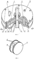
- the engine includes a housing consisting of an upper cover 1 and a lower cover 2, which are connected to each other by bolts 3 through a spacer 4.
- the rotor 5 is secured on an axle 6 between the covers 1 and 2 with the possibility of rotating in bearings 7.
- the rotor 5 has guiding slots on its peripheral portion, with blades 8 freely mounted in the slots.
- the covers 1 and 2 from the side facing the rotor 5 have annular recesses 9 which are made in such a manner that during the assembly of the covers into a single construction, an annular channel 10 is formed for the passage of a working medium, the channel being divided by the rotor 5, the peripheral portion of which, with the blades 8 mounted therein, is placed inside the annular channel 10.
- the annular channel 10 has in cross section, passing through the axle 6, the form of a circle with a diameter corresponding to the diameter of a blade 8.
- the annular channel 10 bends wavelike in accordance with a periodical law, preferably according to a sinusoid 11, symmetrically relative to the middle section of the rotor 5, which is perpendicular to the axle 6.
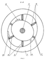
- ports 12 for the inlet of air and ports 13 for the discharge of exhaust gases.
- chambers 14 connected to the channel 10, in which chambers fuel-injection nozzles 15 are placed, and if necessary hot-bulb systems (not shown in the drawings).
- the blade 8 has the form of a flattened cylinder, on the side surface of which two tangential grooves 16 are made, which are positioned diametrically opposite each other.
- the sealing elements formed by the rings 17 are freely mounted in grooves made on the side surface of the disk portions of the blades 8.
- the slots of the rotor 5 in which the blades 8 are mounted have a shape corresponding to the cross section of a blade 8 in its diametral plane perpendicular to the direction of tangential grooves 16, i.e. a H-shaped form.
- the disk portions of a blade 8 enter parallel portions of the slot, and its portion positioned between the grooves 16 and connecting the disk portions enters the portion of the slot connecting the aforesaid parallel portions.
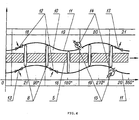
- the channel 10 is divided by the rotor 5 into two parts, each of which may conditionally be divided into zones: 18 - air intake zone, 19 - compression zone, 20 - working stroke zone, 21 - exhaust gases outlet zone.
- each working zone of the upper part of the channel 10 is shifted in respect to a similar working zone of the lower part of the channel by a predetermined angle.
- the shift angle is 90°. In engines with greater power, and consequently with a larger diameter of the rotor, it is advisable to increase the number of periods (bends) of the annular channel. In such a case the shift angle will be smaller.
- the engine works in the following manner.
- the blades 8 execute complex movement: reciprocal in the slots of the rotor 5 in a direction parallel to the axle 6 of the rotor and forward. movement along the annular channel 10. Due to the grooves 16, a blade 8 cannot be displaced along the radius of the rotor 5 during its movement along the axle 6 of the rotor and is too strongly pressed against the wall of the channel 10, for example under the action of centrifugal forces, which could cause jamming of the blade.
- the sinusoidal shape of the channel 10 which is not obligatory, is optimum from the point of view of uniform operation of the engine and prevention of jamming of the blades in the channel during their movement, especially in the case of high frequency of rotor 5 rotation .
- the claimed engine may operate in accordance with the described cycle using any liquid hydrocarbon fuel.
Landscapes
- Engineering & Computer Science (AREA)
- Mechanical Engineering (AREA)
- General Engineering & Computer Science (AREA)
- Ignition Installations For Internal Combustion Engines (AREA)
- Hydraulic Motors (AREA)
- Rotary Pumps (AREA)
- Fuel-Injection Apparatus (AREA)
- Nitrogen And Oxygen Or Sulfur-Condensed Heterocyclic Ring Systems (AREA)
- Structures Of Non-Positive Displacement Pumps (AREA)
- Turbine Rotor Nozzle Sealing (AREA)
Abstract
Description
Claims (2)
- A rotary axial engine comprising a housing consisting of two interconnected covers, a rotor secured on an axle, mounted between the covers and having guiding slots on a peripheral portion thereof, the slots being oriented in radial planes along the axle of the rotor, and blades mounted in the slots with the possibility for their reciprocal movement in a direction parallel to the axis of the rotor, wherein an annular recess is made on an inner surface of each cover of such a configuration that an annular channel for passage of a working medium is formed when the covers are connected, the annular channel having in a section passing through the axis of the rotor a shape corresponding to the shape of the blade and bending wavelike according to a periodic law symmetrically relative to the middle section of the rotor, perpendicular to the axis thereof, the blades are provided with sealing elements, the peripheral portion of the rotor with mounted blades is placed inside the annular channel, and each cover is provided with ports for the supply of air into the annular channel and outlet of exhaust gases, and also with a chamber connected to the annular channel, in which chamber a fuel-injection nozzle is mounted, characterized in that each blade 8 has the form of a flattened cylinder, on the side surface of which there are two tangential grooves 16 positioned diametrically opposite each other, the guiding slots of the rotor 5 have a form corresponding to the cross section of a blade 8 in a diametral plane perpendicular to the direction of the tangential grooves 16, and the sealing elements 17 are mounted on a side surface of the disk portions of a blade 8 with the possibility for their free movement along the perimeter of the disk portions of the blade 8.
- A rotary axial engine according to claim 1, characterized in that the annular channel 10 bends according to a sinusoid.
Applications Claiming Priority (3)
| Application Number | Priority Date | Filing Date | Title |
|---|---|---|---|
| RU98123144A RU2148721C1 (en) | 1998-12-11 | 1998-12-11 | Axial rotary engine |
| RU98123144 | 1998-12-11 | ||
| PCT/RU1999/000479 WO2000036278A2 (en) | 1998-12-11 | 1999-12-10 | Axial rotary engine |
Publications (2)
| Publication Number | Publication Date |
|---|---|
| EP1298284A2 true EP1298284A2 (en) | 2003-04-02 |
| EP1298284A4 EP1298284A4 (en) | 2004-05-12 |
Family
ID=20213710
Family Applications (1)
| Application Number | Title | Priority Date | Filing Date |
|---|---|---|---|
| EP99964807A Withdrawn EP1298284A4 (en) | 1998-12-11 | 1999-12-10 | Axial rotary engine |
Country Status (9)
| Country | Link |
|---|---|
| US (1) | US6401687B1 (en) |
| EP (1) | EP1298284A4 (en) |
| JP (1) | JP3488430B2 (en) |
| KR (1) | KR100452522B1 (en) |
| CN (1) | CN1114027C (en) |
| AU (1) | AU3085700A (en) |
| CA (1) | CA2354393A1 (en) |
| RU (1) | RU2148721C1 (en) |
| WO (1) | WO2000036278A2 (en) |
Cited By (2)
| Publication number | Priority date | Publication date | Assignee | Title |
|---|---|---|---|---|
| WO2006088289A1 (en) * | 2005-02-17 | 2006-08-24 | Woo Gyoon Kim | Free piston rotary engine |
| CN101865023A (en) * | 2010-06-02 | 2010-10-20 | 清华大学 | A New Rotary Combustion Chamber Engine |
Families Citing this family (14)
| Publication number | Priority date | Publication date | Assignee | Title |
|---|---|---|---|---|
| RU2266413C2 (en) * | 2003-11-27 | 2005-12-20 | Осинин Александр Трофимович | Internal combustion engine |
| RU2293857C1 (en) * | 2005-09-01 | 2007-02-20 | Станислав Святославович Сагаков | Wheel-and-vane engine |
| RU2307255C1 (en) * | 2006-06-01 | 2007-09-27 | Анатолий Владимирович Карасев | Method of and device for accomplishing working cycles of rotary internal combustion engine |
| US20080035104A1 (en) * | 2006-07-27 | 2008-02-14 | Mccann James | Redesigned engine cam for rotary engine |
| US7963096B2 (en) * | 2006-11-02 | 2011-06-21 | Vanholstyn Alex | Reflective pulse rotary engine |
| US20080135013A1 (en) * | 2006-11-09 | 2008-06-12 | Abdalla Aref Adel-Gary | Paddling blades engine |
| US8037863B2 (en) * | 2007-03-05 | 2011-10-18 | Hartfield Jr Roy J | Positive displacement rotary vane engine |
| CN101994566B (en) * | 2009-08-11 | 2012-12-05 | 天津职业技术师范大学 | Double-blade rotary motor |
| CN102061982B (en) * | 2011-01-19 | 2013-04-17 | 王仲彦 | Rotating disk type engine |
| US8925516B2 (en) * | 2011-08-01 | 2015-01-06 | Todd Daman | Rotary engine |
| CN103114875A (en) * | 2011-12-12 | 2013-05-22 | 辽宁工程技术大学 | Impeller-typed pneumatic motor of mine-used lifesaving cabin |
| CN104454131B (en) * | 2013-09-18 | 2018-01-30 | 吴结华 | Pie internal combustion engine |
| ES2824463T3 (en) | 2015-02-11 | 2021-05-12 | Uav Engines Ltd | Rotary motor rotor |
| RU2704514C1 (en) * | 2019-01-09 | 2019-10-29 | Анатолий Викторович Леошко | Rotor axial engine and engine lubrication system |
Family Cites Families (15)
| Publication number | Priority date | Publication date | Assignee | Title |
|---|---|---|---|---|
| US268195A (en) * | 1882-11-28 | dayis | ||
| US1686767A (en) * | 1927-03-31 | 1928-10-09 | Saxon James Anglo | Rotary internal-combustion engine |
| US2688385A (en) * | 1952-12-29 | 1954-09-07 | Mclaughlin William | Rotary hydraulic brake machine |
| US4004556A (en) * | 1969-09-08 | 1977-01-25 | Rolf Alfons Pfeiffer | Rotary internal combustion engine of axially sliding vane type |
| US3799710A (en) * | 1972-10-13 | 1974-03-26 | Gen Motors Corp | Vanes for rotary pumps and motors |
| DE2301666A1 (en) * | 1973-01-13 | 1974-07-18 | Friedemann V Prondzinski | HYDROGEN GAS ENGINE |
| US3886910A (en) * | 1973-10-12 | 1975-06-03 | Richard Arnold Vrooman | Rotary, multi-chambered, internal combustion engine |
| DE3218601A1 (en) * | 1982-05-18 | 1983-12-29 | Martin 7430 Metzingen Graser | Rotary-valve internal combustion engine |
| SU1188336A1 (en) * | 1983-01-14 | 1985-10-30 | Специализированное Конструкторское Бюро "Гидрогеотехника" | Rotary machine |
| GB2183732A (en) * | 1985-12-06 | 1987-06-10 | Charles Sejbl | Sinusoidal pump/motor |
| RU2018695C1 (en) * | 1991-03-05 | 1994-08-30 | Васильев Виктор Анатольевич | Pneumatic rotary engine |
| AU4938693A (en) * | 1992-08-19 | 1994-03-15 | Brian W. Cherry | Axial vane rotary engine with rounded vanes |
| US5429084A (en) * | 1994-02-25 | 1995-07-04 | Sky Technologies, Inc. | Axial vane rotary device and sealing system therefor |
| US5509793A (en) * | 1994-02-25 | 1996-04-23 | Regi U.S., Inc. | Rotary device with slidable vane supports |
| US6022201A (en) * | 1996-05-14 | 2000-02-08 | Kasmer Hydristor Corporation | Hydraulic vane pump with flexible band control |
-
1998
- 1998-12-11 RU RU98123144A patent/RU2148721C1/en not_active IP Right Cessation
-
1999
- 1999-12-10 EP EP99964807A patent/EP1298284A4/en not_active Withdrawn
- 1999-12-10 CN CN99814236A patent/CN1114027C/en not_active Expired - Fee Related
- 1999-12-10 JP JP2000588497A patent/JP3488430B2/en not_active Expired - Fee Related
- 1999-12-10 AU AU30857/00A patent/AU3085700A/en not_active Abandoned
- 1999-12-10 CA CA002354393A patent/CA2354393A1/en not_active Abandoned
- 1999-12-10 WO PCT/RU1999/000479 patent/WO2000036278A2/en not_active Ceased
- 1999-12-10 US US09/857,894 patent/US6401687B1/en not_active Expired - Fee Related
-
2001
- 2001-06-09 KR KR10-2001-7007243A patent/KR100452522B1/en not_active Expired - Fee Related
Cited By (2)
| Publication number | Priority date | Publication date | Assignee | Title |
|---|---|---|---|---|
| WO2006088289A1 (en) * | 2005-02-17 | 2006-08-24 | Woo Gyoon Kim | Free piston rotary engine |
| CN101865023A (en) * | 2010-06-02 | 2010-10-20 | 清华大学 | A New Rotary Combustion Chamber Engine |
Also Published As
| Publication number | Publication date |
|---|---|
| RU2148721C1 (en) | 2000-05-10 |
| WO2000036278A3 (en) | 2003-01-23 |
| CN1329695A (en) | 2002-01-02 |
| KR100452522B1 (en) | 2004-10-12 |
| AU3085700A (en) | 2000-07-03 |
| JP2003520921A (en) | 2003-07-08 |
| KR20010101164A (en) | 2001-11-14 |
| WO2000036278A2 (en) | 2000-06-22 |
| EP1298284A4 (en) | 2004-05-12 |
| US6401687B1 (en) | 2002-06-11 |
| JP3488430B2 (en) | 2004-01-19 |
| CA2354393A1 (en) | 2000-06-22 |
| CN1114027C (en) | 2003-07-09 |
Similar Documents
| Publication | Publication Date | Title |
|---|---|---|
| US6401687B1 (en) | Axial rotary engine | |
| US5431551A (en) | Rotary positive displacement device | |
| US5352295A (en) | Rotary vane engine | |
| US6776136B1 (en) | Elliptical rotary engine | |
| US4480973A (en) | Vane compressor provided with endless camming surface minimizing torque fluctuations | |
| EP0933500A1 (en) | Rotary piston machine | |
| US10344870B2 (en) | Apex seal arrangement for rotary internal combustion engine | |
| US4605361A (en) | Oscillating vane rotary pump or motor | |
| EP1335109A1 (en) | Volumetric rotary machine | |
| US6298821B1 (en) | Bolonkin rotary engine | |
| US4097205A (en) | Orbital pump with inlet and outlet through the rotor | |
| US3323501A (en) | Rotary blade piston engine | |
| RU10217U1 (en) | ROTARY AXIAL ENGINE | |
| US4209001A (en) | Orbital internal combustion engine | |
| RU2076220C1 (en) | Rotary-piston internal combustion engine | |
| US3937605A (en) | Rotary piston machine | |
| RU2063526C1 (en) | Rotary engine | |
| US4221553A (en) | Oribital pump with fluid flow control | |
| RU2606035C1 (en) | Rotary-vane engine with separate rotary combustion chamber | |
| JP2007501354A (en) | Rotary machine with main and satellite rotors | |
| RU2120042C1 (en) | Rotary piston internal combustion engine | |
| RU2704514C1 (en) | Rotor axial engine and engine lubrication system | |
| RU2816772C1 (en) | Rotary machine | |
| RU2052143C1 (en) | Rotor internal combustion engine | |
| RU2413078C2 (en) | Rotory ait engine |
Legal Events
| Date | Code | Title | Description |
|---|---|---|---|
| PUAI | Public reference made under article 153(3) epc to a published international application that has entered the european phase |
Free format text: ORIGINAL CODE: 0009012 |
|
| 17P | Request for examination filed |
Effective date: 20010628 |
|
| AK | Designated contracting states |
Kind code of ref document: A2 Designated state(s): AT BE CH CY DE DK ES FI FR GB GR IE IT LI LU MC NL PT SE Designated state(s): AT BE CH CY DE DK ES FI FR GB GR IE IT LI LU MC NL PT SE |
|
| RAP1 | Party data changed (applicant data changed or rights of an application transferred) |
Owner name: GREATWOOD SELECT LIMITED |
|
| A4 | Supplementary search report drawn up and despatched |
Effective date: 20040329 |
|
| RIC1 | Information provided on ipc code assigned before grant |
Ipc: 7F 01C 1/344 B Ipc: 7F 01C 1/00 A |
|
| GRAP | Despatch of communication of intention to grant a patent |
Free format text: ORIGINAL CODE: EPIDOSNIGR1 |
|
| STAA | Information on the status of an ep patent application or granted ep patent |
Free format text: STATUS: THE APPLICATION IS DEEMED TO BE WITHDRAWN |
|
| 18D | Application deemed to be withdrawn |
Effective date: 20060113 |