EP1297859B1 - Safety catheter - Google Patents
Safety catheter Download PDFInfo
- Publication number
- EP1297859B1 EP1297859B1 EP02256710A EP02256710A EP1297859B1 EP 1297859 B1 EP1297859 B1 EP 1297859B1 EP 02256710 A EP02256710 A EP 02256710A EP 02256710 A EP02256710 A EP 02256710A EP 1297859 B1 EP1297859 B1 EP 1297859B1
- Authority
- EP
- European Patent Office
- Prior art keywords
- catheter
- needle
- flange
- needle assembly
- tip protector
- Prior art date
- Legal status (The legal status is an assumption and is not a legal conclusion. Google has not performed a legal analysis and makes no representation as to the accuracy of the status listed.)
- Expired - Lifetime
Links
Images


Classifications
-
- A—HUMAN NECESSITIES
- A61—MEDICAL OR VETERINARY SCIENCE; HYGIENE
- A61M—DEVICES FOR INTRODUCING MEDIA INTO, OR ONTO, THE BODY; DEVICES FOR TRANSDUCING BODY MEDIA OR FOR TAKING MEDIA FROM THE BODY; DEVICES FOR PRODUCING OR ENDING SLEEP OR STUPOR
- A61M25/00—Catheters; Hollow probes
- A61M25/01—Introducing, guiding, advancing, emplacing or holding catheters
- A61M25/06—Body-piercing guide needles or the like
- A61M25/0612—Devices for protecting the needle; Devices to help insertion of the needle, e.g. wings or holders
- A61M25/0618—Devices for protecting the needle; Devices to help insertion of the needle, e.g. wings or holders having means for protecting only the distal tip of the needle, e.g. a needle guard
-
- A—HUMAN NECESSITIES
- A61—MEDICAL OR VETERINARY SCIENCE; HYGIENE
- A61M—DEVICES FOR INTRODUCING MEDIA INTO, OR ONTO, THE BODY; DEVICES FOR TRANSDUCING BODY MEDIA OR FOR TAKING MEDIA FROM THE BODY; DEVICES FOR PRODUCING OR ENDING SLEEP OR STUPOR
- A61M5/00—Devices for bringing media into the body in a subcutaneous, intra-vascular or intramuscular way; Accessories therefor, e.g. filling or cleaning devices, arm-rests
- A61M5/178—Syringes
- A61M5/31—Details
- A61M5/32—Needles; Details of needles pertaining to their connection with syringe or hub; Accessories for bringing the needle into, or holding the needle on, the body; Devices for protection of needles
- A61M5/3205—Apparatus for removing or disposing of used needles or syringes, e.g. containers; Means for protection against accidental injuries from used needles
- A61M5/321—Means for protection against accidental injuries by used needles
- A61M5/3243—Means for protection against accidental injuries by used needles being axially-extensible, e.g. protective sleeves coaxially slidable on the syringe barrel
- A61M5/3245—Constructional features thereof, e.g. to improve manipulation or functioning
- A61M2005/3247—Means to impede repositioning of protection sleeve from needle covering to needle uncovering position
- A61M2005/325—Means obstructing the needle passage at distal end of a needle protection sleeve
-
- A—HUMAN NECESSITIES
- A61—MEDICAL OR VETERINARY SCIENCE; HYGIENE
- A61M—DEVICES FOR INTRODUCING MEDIA INTO, OR ONTO, THE BODY; DEVICES FOR TRANSDUCING BODY MEDIA OR FOR TAKING MEDIA FROM THE BODY; DEVICES FOR PRODUCING OR ENDING SLEEP OR STUPOR
- A61M5/00—Devices for bringing media into the body in a subcutaneous, intra-vascular or intramuscular way; Accessories therefor, e.g. filling or cleaning devices, arm-rests
- A61M5/178—Syringes
- A61M5/31—Details
- A61M5/32—Needles; Details of needles pertaining to their connection with syringe or hub; Accessories for bringing the needle into, or holding the needle on, the body; Devices for protection of needles
- A61M5/3205—Apparatus for removing or disposing of used needles or syringes, e.g. containers; Means for protection against accidental injuries from used needles
- A61M5/321—Means for protection against accidental injuries by used needles
- A61M5/3243—Means for protection against accidental injuries by used needles being axially-extensible, e.g. protective sleeves coaxially slidable on the syringe barrel
- A61M5/3273—Means for protection against accidental injuries by used needles being axially-extensible, e.g. protective sleeves coaxially slidable on the syringe barrel freely sliding on needle shaft without connection to syringe or needle
Definitions
- the present invention relates, in general, to intravenous (IV) catheters and, more particularly, to a safety IV catheter with a needle tip protector that will automatically cover the needle tip upon needle withdrawal.
- IV intravenous
- I.V. catheters are used primarily to administer fluids directly into a patient's vascular system.
- the catheter is inserted into a patient's vein by a clinician using a handheld placement device that includes a needle with a sharp distal end.
- the needle is positioned in the interior hollow portion of the catheter with its sharp distal tip extended slightly beyond the distal edge of the catheter.
- the proximal end of the needle is connected to a needle hub which is held by the clinician during the insertion procedure.
- the clinician inserts the needle and catheter together into the patient's vein.
- the catheter is forwarded into the vein of the patient by the clinician pushing the catheter with their finger.
- the clinician then withdraws just the needle by grasping the hub attached to the proximal end of the needle while at the same time applying pressure to the patient's skin at the insertion site, thus holding the catheter fixed in place.
- the clinician then typically tapes the proximal end of the now inserted catheter to the patient's skin and connects the proximal end of the catheter, containing a Luer connector catheter hub, to the source of the fluid to be administered into the patient's vein.
- a safety catheter which includes an element which covers the needle tip upon removal of the needle from the catheter.
- the safety element includes a split flange at its proximal end which is expanded by the needle as the needle is inserted into an undersized hole at the center of this flange. The safety element is thus held secure within the catheter hub by inserting the needle through the undersized hole which forces the outside perimeter of the split flange against the inside wall of the catheter hub.
- a safety IV catheter including a resilient needle guard which protects the needle tip upon removal of the needle from the catheter hub.
- the needle guard includes an arm that includes an opening through which a needle passes causing radial movement of the arm. This radial movement forces the arm into a groove or behind a rib located on the inside of the catheter hub, capturing the needle guard in the catheter hub.
- a potential issue with this design develops when the needle guard is not properly seated into the catheter hub. If the distal end of the needle guard arm is not in alignment with the groove in the catheter hub, excessive forces are placed on the needle causing a high drag force as the clinician removes the needle. And, since the needle guard arm is not properly seated in the groove, it may prematurely release from the catheter hub upon the removal of the needle leaving the needle tip exposed.
- a catheter and introducer needle assembly including a needle having a diameter, proximal end, attached to a needle hub, a distal end, and a enlarged area disposed therebetween.
- the assembly further includes a tubular catheter having proximal and distal ends, the introducer needle being coaxially received within the catheter, and a hollow catheter hub having a distal end attached to the proximal end of the catheter and in fluid communication with the catheter.
- the catheter hub includes an interior having a raised annular rib disposed thereon.
- the assembly also includes a needle tip protector having a proximal end and a distal end disposed within the catheter hub.
- the proximal end including at least one unrestrained radially extending lip disposed distal to the annular rib so as to retain the protector within the hub, wherein the distal end of the protector does not abut against the hub interior.
- the protector having a proximal opening at the proximal end having an unrestrained size greater than the size of the needle diameter and smaller than the enlarged area such that when the needle is removed from the catheter the protector remains attached to the needle.
- proximal refers to a location on the catheter and needle assembly with needle tip protector closest to the clinician using the device and thus furthest from the patient on which the device is used.
- distal refers to a location farthest from the clinician and closest to the patient.
- IV catheter assembly 20 comprises catheter assembly 22 and needle assembly 24. Needle assembly 24 further includes needle tip protector 26.
- Catheter assembly 22 includes catheter 28 which is a tubular structure having a proximal end 31 and distal end 29. Proximal end 31 of catheter 28 is fixedly attached to catheter hub 30.
- catheter 28 is a tubular structure having a proximal end 31 and distal end 29. Proximal end 31 of catheter 28 is fixedly attached to catheter hub 30.
- catheter hub 30 is well known in the medical art and one of many suitable materials, most of which are flexible thermoplastics, may be selected for use in catheter 28. Such materials may include, for example, polyurethane or fluorinated ethylene propylene.
- Catheter hub 30 is a generally tubular structure having an internal cavity in fluid communication with the internal lumen of catheter 28.
- Catheter hub 30 may be made from a suitable, rigid medical grade thermoplastic such as, for example, polypropylene or polycarbonate.
- catheter hub 30 is shown translucent, though in actual use it may be translucent or opaque.
- Luer fitting 32 is integrally attached at the proximal end of catheter hub 30 .
- Luer fitting 32 provides for secure, leakproof attachment of tubing, syringes, or any of many other medical devices used to infuse or withdraw fluids through the catheter assembly.
- rib 34 is a raised annular ring integral to and extending from internal sidewall 36 of catheter hub 30. Rib 34 is located approximately mid way between the proximal end and distal end of sidewall 36. Rib 34 plays an important role in securing needle tip protector 26 in catheter hub 30, as will be described in more detail later.
- needle assembly 24 comprises needle 38, which is a tubular structure with a proximal end 39 and distal end 41, needle hub 40, and needle tip protector 26. Needle tip protector 26 is assembled slidably on needle 38. Needle 38 is preferably made of stainless steel. Proximal end 39 of needle 38 is fixedly attached to needle hub 40. A bevel 42 is located at the most distal end of needle 38 creating a sharp piercing tip. Needle crimp 44 is located at the distal end of needle 38 proximal to bevel 42 and is larger in diameter than the nominal diameter of needle 38.
- Needle crimp 44 is created by "coining" an area on the outside diameter of needle 38 resulting in two opposed bumps located approximately 180 degrees across the center axis of needle 38.
- Coining is a process well known in the metal forming art and involves using a hardened tool to strike a softer object to deform or displace a portion of the softer object.
- a portion of the exterior surface of the softer metal needle 38 is displaced by a harder metal tool so as to raise bumps on the exterior surface of needle 38.
- the resulting crimp 44 is larger in dimension than the nominal diameter of needle 38.
- Crimp 44 is larger in dimension than the diameter of second flange hole 72 in needle tip protector 26 and is important in preventing the complete removal of needle tip protector 26 from needle 38, as will be described in more detail later.
- the dimension across crimp 44 is 0.0025-0.01 mm (.0001- .004 inches) larger than second flange hole 72, dependant upon needle "gauge" size.
- Needle hub 40 is generally a tubular structure having an internal cavity in fluid communication with the lumen in needle 38. It is preferably made of a translucent or transparent generally rigid thermoplastic material such as, for example, polycarbonate. At the most proximal end of the internal cavity in needle hub 40 is fixedly attached porous plug 46. A flashback chamber 48 is created in the cavity distal to porous plug 46. Porous plug 46 contains a plurality of microscopic openings which are large enough to permit the passage of air and other gasses but small enough to prevent the passage of blood. Flashback chamber 48 fills with blood upon successful entry of the needle tip into the targeted vein, providing the clinician visual conformation of the correct placement of the needle.
- needle tip protector 26 has a proximal end 49 and distal end 50 and is preferably a unitary structure formed from a single piece of thin, resilient material, preferably stainless steel.
- First flange 66 and second flange 68 are generally square and are integrally connected at right angles to first outer wall 74 and second outer wall 76, respectively.
- First outer wall 74 is connected at a right angle to first tab flange 78.
- First tab flange 78 and second tab flange 80 are each formed at angles slightly greater than 90 degrees to second outer wall 76 so that the resulting dimension c is slightly larger than inside diameter d (see Figures 6 - 7 ) across rib 34 in catheter hub 30.
- angles a and b are each approximately 94.25 degrees.
- dimension c is approximately 0.0025-0.023 mm (.001 - .009 inches) larger than dimension d.
- First flange hole 70 is located in the center of first flange 66 and is over-sized to slidably receive needle 38.
- Second flange hole 72 and skirt 82 are located in the center of second flange 68.
- Skirt 82 is integral to second flange hole 72 and is formed by extruding material from second flange hole 72 in a direction distal to second flange 68. This permits for a very close but slidable fit over the nominal diameter of needle 38.
- Skirt 82 also functions to help maintain alignment of needle 38 to the center axis of needle tip protector 26.
- flange hole 72 would be appropriately sized to the particular needle "gauge" size to which it is designed to receive.
- First tab 86 and second tab 88 are connected at right angles to first tab flange 78 and second tab flange 80, respectively, and protrude outward away from the center axis of needle tip protector 26.
- First tab edge 90, located on the outer portion of first tab 86, and second tab edge 92, located on the outer portion of second tab 88, are each arcuate to approximately match the curve of sidewall 36 in catheter hub 30.
- first beam 96 extends distally from first outer wall 74 and is angled toward and extends past the center axis of needle tip protector 26.
- first beam 96 extends distally from first outer wall 74 and is angled toward and extends past the center axis of needle tip protector 26.
- Second beam 100 extends distally from second outer wall 76 and is angled toward and extends past the center axis of needle tip protector 26.
- stop flange 102 which extends across and normal to the center axis of needle tip protector 26.
- stop flange 102 opposite its connection to second beam 100 is integrally formed curved second lip 104.
- needle tip protector 26 is assembled to needle 38 as follows;
- needle assembly 24, including needle tip protector 26, is assembled into catheter assembly 22 as follows;
- Needle tip protector 26 is thus held distal to rib 34 inside the cavity in catheter hub 30 by the flexural forces of first tab 86 and second tab 88 since dimension c on needle tip protector 26 is larger than dimension d across rib 34 inside catheter hub 30. (see figure 6 ).
- first tab 86 and second tab 88 as needle tip protector 26 is finally seated distal to rib 34 causes flexure in second outer wall 76 and first tab flange 78 resulting in the approximate alignment of first flange hole 70 and second flange hole 72.
- the IV catheter assembly 20 of the present invention functions as follows;
- needle tip protector 126 is preferably a unitary structure formed from a single piece of thin, resilient material such as, for example, stainless steel, similar to needle tip protector 26.
- Needle tip protector 126 includes first flange 166 and second flange 168.
- First flange 166 and second flange 168 are generally arcuate and are integrally connected to first outer wall 174 and second outer wall 176, respectively.
- Extending distally from first outer wall 174 of needle tip protector 126 is first beam 196.
- First beam 196 which has an arcuate outer edge, is angled toward and extends past the center axis of needle tip protector 126.
- First beam 196 further includes first rib 314 coined therein to add stiffness.
- first beam 196 At the distal end of first beam 196 is integrally formed curved first lip 198 which extends across and through the center axis of needle tip protector 126. Extending distally from second outer wall 176 of needle tip protector 126 is second beam 200. Second beam 200, which has an arcuate outer edge, is angled toward and extends past the center axis of needle tip protector 126. Second beam 200 further includes second rib 316 (not visible) coined therein to add stiffness. The distal end of second beam 200 is connected to the proximal end of wing base 306. Wing base 306 extends across and parallel to the center axis of needle tip protector 126. Wing base 306 further comprises first wing side 308 and second wing side 310.
- Wing 312 Integrally attached to first wing side 308 of wing base 306 at approximately a 90° angle is wing 312.
- Wing 312 which extends parallel to the center axis of needle tip protector 126, prevents any further radial movement of needle 138 by retaining it within needle tip protector 126.
- Stop flange 302 extends across needle 138 and is angled toward the center axis of needle tip protector 126.
- Second lip 304 is curved toward proximal end 149 of needle tip protector 126 to prevent any further distal movement of needle 138.
Description
- The present invention relates, in general, to intravenous (IV) catheters and, more particularly, to a safety IV catheter with a needle tip protector that will automatically cover the needle tip upon needle withdrawal.
- I.V. catheters are used primarily to administer fluids directly into a patient's vascular system. The catheter is inserted into a patient's vein by a clinician using a handheld placement device that includes a needle with a sharp distal end. The needle is positioned in the interior hollow portion of the catheter with its sharp distal tip extended slightly beyond the distal edge of the catheter. The proximal end of the needle is connected to a needle hub which is held by the clinician during the insertion procedure.
- During the insertion procedure, the clinician inserts the needle and catheter together into the patient's vein. After insertion of the needle point into the vein, the catheter is forwarded into the vein of the patient by the clinician pushing the catheter with their finger. The clinician then withdraws just the needle by grasping the hub attached to the proximal end of the needle while at the same time applying pressure to the patient's skin at the insertion site, thus holding the catheter fixed in place. The clinician then typically tapes the proximal end of the now inserted catheter to the patient's skin and connects the proximal end of the catheter, containing a Luer connector catheter hub, to the source of the fluid to be administered into the patient's vein.
- It is the period of time just as the needle is withdrawn from the catheter that poses great risk to the clinician. The clinician is at risk of an accidental needle stick from the sharp needle which has just been contaminated with a patients blood. This leaves the clinician vulnerable to the transmission of dangerous blood-borne pathogens, including hepatitis and AIDS. The risk of a contaminated needle stick is not isolated just to clinicians. Careless disposal of used needles can put other health care workers at risk as well. Even others outside the health care profession, for example those involved in the clean-up and final disposal of medical waste, are at risk of an accidental needle stick from a carelessly discarded needle.
- A number of "safety" IV catheters have been developed to address the issue of accidental needle stick. For example, in
US Patent No. Re. 34,416 to Lemieux, a safety catheter is disclosed which includes an element which covers the needle tip upon removal of the needle from the catheter. The safety element includes a split flange at its proximal end which is expanded by the needle as the needle is inserted into an undersized hole at the center of this flange. The safety element is thus held secure within the catheter hub by inserting the needle through the undersized hole which forces the outside perimeter of the split flange against the inside wall of the catheter hub. - One of the drawbacks to this design is the amount of friction force exerted against the needle by the split flange. A tight fit of the flange against the catheter wall causes great friction against the needle making it difficult to be withdrawn from the catheter by the clinician. A loose fit leaves the flange prone to releasing prematurely from the catheter as the needle is withdrawn, creating the potential that the needle tip will be left exposed.
- In
US Patent No. 6,117,108 to Woehr et al, a safety IV catheter is described including a resilient needle guard which protects the needle tip upon removal of the needle from the catheter hub. The needle guard includes an arm that includes an opening through which a needle passes causing radial movement of the arm. This radial movement forces the arm into a groove or behind a rib located on the inside of the catheter hub, capturing the needle guard in the catheter hub. A potential issue with this design develops when the needle guard is not properly seated into the catheter hub. If the distal end of the needle guard arm is not in alignment with the groove in the catheter hub, excessive forces are placed on the needle causing a high drag force as the clinician removes the needle. And, since the needle guard arm is not properly seated in the groove, it may prematurely release from the catheter hub upon the removal of the needle leaving the needle tip exposed. - The prior art safety catheters all exhibit one or more drawbacks that have thus far limited their usefulness and full acceptance by health-care workers. What is needed therefore is a safety IV catheter that functions reliably, is easy and inexpensive to manufacture, and easy to use.
- The features of the present invention that are known from
EP 0 750 916 have been placed in the preamble of claim 1 appended hereto. - In accordance with the present invention there is provided a catheter and introducer needle assembly including a needle having a diameter, proximal end, attached to a needle hub, a distal end, and a enlarged area disposed therebetween. The assembly further includes a tubular catheter having proximal and distal ends, the introducer needle being coaxially received within the catheter, and a hollow catheter hub having a distal end attached to the proximal end of the catheter and in fluid communication with the catheter. The catheter hub includes an interior having a raised annular rib disposed thereon. The assembly also includes a needle tip protector having a proximal end and a distal end disposed within the catheter hub. The proximal end including at least one unrestrained radially extending lip disposed distal to the annular rib so as to retain the protector within the hub, wherein the distal end of the protector does not abut against the hub interior. The protector having a proximal opening at the proximal end having an unrestrained size greater than the size of the needle diameter and smaller than the enlarged area such that when the needle is removed from the catheter the protector remains attached to the needle.
- The novel features of the invention are set forth with particularity in the appended claims. The invention itself, however, both as to organization and methods of operation, together with further objects and advantages thereof, may best be understood by reference to the following description, taken in conjunction with the accompanying drawings in which:
-
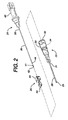
Figure 1 is a perspective view of the catheter and needle assembly of the present invention; -
Figure 2 is an exploded perspective view of the catheter assembly and needle assembly including the needle tip protector of the present invention; -
Figure 3 is a perspective view of the needle tip protector of the present invention; -
Figure 4 is an elevation view ofFigure 3 taken along line 4-4 illustrating the hole positions in the rear flanges of the needle tip protector as manufactured; -
Figure 5 is a section view of the catheter assembly and needle assembly taken along line 5-5 ofFigure 1 ; -
Figure 6 is an enlarged partial section view ofFigure 5 illustrating the relative position of the needle tip protector tab and catheter hub rib; -
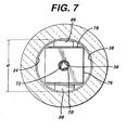
Figure 7 is a section view of the catheter hub with needle tip protector installed taken along line 7 - 7 ofFigure 5 ; -
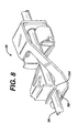
Figure 8 is a perspective view of the needle tip protector shown as installed in the catheter hub with the needle inserted there through, catheter hub not shown for clarity; -
Figure 9 is a perspective view of the needle tip protector shown as removed from the catheter hub and illustrating the needle tip covered by the protector; -
Figure 10 is a perspective view of an alternate embodiment of the needle tip protector of the present invention. - As used herein, the term "proximal" refers to a location on the catheter and needle assembly with needle tip protector closest to the clinician using the device and thus furthest from the patient on which the device is used. Conversely, the term "distal" refers to a location farthest from the clinician and closest to the patient.
- As illustrated in
Figures 1 and2 , IVcatheter assembly 20 comprisescatheter assembly 22 andneedle assembly 24.Needle assembly 24 further includesneedle tip protector 26.Catheter assembly 22 includescatheter 28 which is a tubular structure having aproximal end 31 anddistal end 29.Proximal end 31 ofcatheter 28 is fixedly attached tocatheter hub 30. Catheters are well known in the medical art and one of many suitable materials, most of which are flexible thermoplastics, may be selected for use incatheter 28. Such materials may include, for example, polyurethane or fluorinated ethylene propylene.Catheter hub 30 is a generally tubular structure having an internal cavity in fluid communication with the internal lumen ofcatheter 28.Catheter hub 30 may be made from a suitable, rigid medical grade thermoplastic such as, for example, polypropylene or polycarbonate. For illustrationpurposes catheter hub 30 is shown translucent, though in actual use it may be translucent or opaque. At the proximal end ofcatheter hub 30 is integrally attached Luer fitting 32, commonly known in the medical art. Luer fitting 32 provides for secure, leakproof attachment of tubing, syringes, or any of many other medical devices used to infuse or withdraw fluids through the catheter assembly. As is more clearly illustrated inFigures 5 and 6 ,rib 34 is a raised annular ring integral to and extending frominternal sidewall 36 ofcatheter hub 30.Rib 34 is located approximately mid way between the proximal end and distal end ofsidewall 36.Rib 34 plays an important role in securingneedle tip protector 26 incatheter hub 30, as will be described in more detail later. - Referring again to
Figures 1 and2 ,needle assembly 24 comprisesneedle 38, which is a tubular structure with aproximal end 39 anddistal end 41,needle hub 40, andneedle tip protector 26.Needle tip protector 26 is assembled slidably onneedle 38.Needle 38 is preferably made of stainless steel.Proximal end 39 ofneedle 38 is fixedly attached toneedle hub 40. Abevel 42 is located at the most distal end ofneedle 38 creating a sharp piercing tip.Needle crimp 44 is located at the distal end ofneedle 38 proximal to bevel 42 and is larger in diameter than the nominal diameter ofneedle 38.Needle crimp 44 is created by "coining" an area on the outside diameter ofneedle 38 resulting in two opposed bumps located approximately 180 degrees across the center axis ofneedle 38. Coining is a process well known in the metal forming art and involves using a hardened tool to strike a softer object to deform or displace a portion of the softer object. In the present case a portion of the exterior surface of thesofter metal needle 38 is displaced by a harder metal tool so as to raise bumps on the exterior surface ofneedle 38. The resultingcrimp 44 is larger in dimension than the nominal diameter ofneedle 38.Crimp 44 is larger in dimension than the diameter ofsecond flange hole 72 inneedle tip protector 26 and is important in preventing the complete removal ofneedle tip protector 26 fromneedle 38, as will be described in more detail later. In the preferred embodiment the dimension acrosscrimp 44 is 0.0025-0.01 mm (.0001- .004 inches) larger thansecond flange hole 72, dependant upon needle "gauge" size. -
Needle hub 40 is generally a tubular structure having an internal cavity in fluid communication with the lumen inneedle 38. It is preferably made of a translucent or transparent generally rigid thermoplastic material such as, for example, polycarbonate. At the most proximal end of the internal cavity inneedle hub 40 is fixedly attachedporous plug 46. Aflashback chamber 48 is created in the cavity distal toporous plug 46.Porous plug 46 contains a plurality of microscopic openings which are large enough to permit the passage of air and other gasses but small enough to prevent the passage of blood.Flashback chamber 48 fills with blood upon successful entry of the needle tip into the targeted vein, providing the clinician visual conformation of the correct placement of the needle. - Referring now to all figures,
needle tip protector 26 has aproximal end 49 anddistal end 50 and is preferably a unitary structure formed from a single piece of thin, resilient material, preferably stainless steel.First flange 66 andsecond flange 68 are generally square and are integrally connected at right angles to firstouter wall 74 and secondouter wall 76, respectively. Firstouter wall 74 is connected at a right angle tofirst tab flange 78.First tab flange 78 andsecond tab flange 80 are each formed at angles slightly greater than 90 degrees to secondouter wall 76 so that the resulting dimension c is slightly larger than inside diameter d (seeFigures 6 - 7 ) acrossrib 34 incatheter hub 30. In the preferred embodiment angles a and b are each approximately 94.25 degrees. In the preferred embodiment dimension c is approximately 0.0025-0.023 mm (.001 - .009 inches) larger than dimension d.First flange hole 70 is located in the center offirst flange 66 and is over-sized to slidably receiveneedle 38.Second flange hole 72 andskirt 82 are located in the center ofsecond flange 68.Skirt 82 is integral tosecond flange hole 72 and is formed by extruding material fromsecond flange hole 72 in a direction distal tosecond flange 68. This permits for a very close but slidable fit over the nominal diameter ofneedle 38.Skirt 82 also functions to help maintain alignment ofneedle 38 to the center axis ofneedle tip protector 26. As would be understood by one skilled in the art,flange hole 72 would be appropriately sized to the particular needle "gauge" size to which it is designed to receive. -
First tab 86 andsecond tab 88 are connected at right angles tofirst tab flange 78 andsecond tab flange 80, respectively, and protrude outward away from the center axis ofneedle tip protector 26.First tab edge 90, located on the outer portion offirst tab 86, andsecond tab edge 92, located on the outer portion ofsecond tab 88, are each arcuate to approximately match the curve ofsidewall 36 incatheter hub 30. - Referring again to
Figure 3 ,first beam 96 extends distally from firstouter wall 74 and is angled toward and extends past the center axis ofneedle tip protector 26. At the distal end offirst beam 96 is integrally formed curvedfirst lip 98 which extends across and through the center axis ofneedle tip protector 26.Second beam 100 extends distally from secondouter wall 76 and is angled toward and extends past the center axis ofneedle tip protector 26. At the distal end ofsecond beam 100 is stop flange 102 which extends across and normal to the center axis ofneedle tip protector 26. At the end ofstop flange 102 opposite its connection tosecond beam 100 is integrally formed curvedsecond lip 104. - Referring now to all figures,
needle tip protector 26 is assembled toneedle 38 as follows; - The proximal end of
needle 38 is fixedly attached to the distal end ofneedle hub 40, which containsporous plug 46 fixedly attached to its proximal end; - The distal end of
needle 38 is inserted throughfirst flange hole 70 and then throughsecond flange hole 72 inneedle tip protector 26, moving from proximal to distal; -
First beam 96 andsecond beam 100 are flexed, as a result of their resilient properties, normal to the center axis ofneedle tip protector 26 so thatneedle 38 will pass betweenfirst lip 98 and second lip 104 (seeFigure 8 ); -
Needle crimp 44 is added to the distal end ofneedle 38 just proximal tobevel 42. -
Crimp 44 increases the diameter ofneedle 38 locally to a dimension larger than the inside diameter of second flange hole 72 (seeFigure 9 ) thus preventing the complete removal ofneedle tip protector 26 from the distal end ofneedle 38. - Now
needle assembly 24, includingneedle tip protector 26, is assembled intocatheter assembly 22 as follows; - The distal end of
needle 38 is positioned into the proximal end ofcatheter hub 30 andneedle assembly 24 is moved distally causingneedle 38 to entercatheter 28; - As
needle assembly 24 continues to move distally,needle tip protector 26 enters the opening in the proximal end ofcatheter hub 30; - Continued distal movement of
needle assembly 24 causes the distal edge ofneedle hub 40 to pushfirst tab 86 andsecond tab 88 onneedle tip protector 26 into contact withrib 34 located onhub sidewall 36; - Continued distal movement forces
first tab 86 andsecond tab 88, due to the resilient properties ofneedle tip protector 26,past rib 34 and in contact withsidewall 36, just distal torib 34. -
Needle tip protector 26 is thus held distal torib 34 inside the cavity incatheter hub 30 by the flexural forces offirst tab 86 andsecond tab 88 since dimension c onneedle tip protector 26 is larger than dimension d acrossrib 34 insidecatheter hub 30. (seefigure 6 ). - As is best illustrated in
Figure 7 , the movement offirst tab 86 andsecond tab 88 asneedle tip protector 26 is finally seated distal torib 34 causes flexure in secondouter wall 76 andfirst tab flange 78 resulting in the approximate alignment offirst flange hole 70 andsecond flange hole 72. - Now, in actual clinical use, the
IV catheter assembly 20 of the present invention functions as follows; - The distal end of
needle 38 which extends just past the distal end ofcatheter 28 is inserted into the patient's vein; - The clinician observes blood in the flash chamber in
needle hub 40; - The clinician grasps
needle hub 40, andcatheter assembly 22 alone is moved distally into the vein; - The clinician applies slight pressure to the insertion site to hold
catheter assembly 22 secure; - The clinician grasps the needle hub and begins withdrawal of
needle assembly 24 fromcatheter assembly 22. During this process,needle tip protector 26 remains secureinside catheter hub 30 until raisedcrimp 44 on the distal end ofneedle 38 comes into contact withsecond flange hole 72. Just before raisedcrimp 44 encounterssecond flange hole 72, the biasing forces offirst beam 96 andsecond beam 100cause stop flange 102 andfirst lip 98 to move normal to and across the center axis ofneedle 38, blocking any further distal movement ofneedle 38 relative toneedle tip protector 26; - Since
crimp 44 is larger thansecond flange hole 72, continued proximal movement ofneedle 38 carriesneedle tip protector 26 proximal as well, forcingfirst tab 86 andsecond tab 88 onneedle tip protector 26 againstrib 34.First tab 86 andsecond tab 88 are forced to flex normal to and toward the center axis ofneedle tip protector 26, permitting continued movement proximal,past rib 34; -
Needle assembly 24 is now removed entirely fromcatheter assembly 22, with the needle tip covered byneedle tip protector 26 of the present invention. -
Figure 10 shows an alternate embodiment of the present invention. In this embodiment,needle tip protector 126, is preferably a unitary structure formed from a single piece of thin, resilient material such as, for example, stainless steel, similar toneedle tip protector 26.Needle tip protector 126 includesfirst flange 166 andsecond flange 168.First flange 166 andsecond flange 168 are generally arcuate and are integrally connected to firstouter wall 174 and secondouter wall 176, respectively. Extending distally from firstouter wall 174 ofneedle tip protector 126 isfirst beam 196.First beam 196, which has an arcuate outer edge, is angled toward and extends past the center axis ofneedle tip protector 126.First beam 196 further includesfirst rib 314 coined therein to add stiffness. - At the distal end of
first beam 196 is integrally formed curvedfirst lip 198 which extends across and through the center axis ofneedle tip protector 126. Extending distally from secondouter wall 176 ofneedle tip protector 126 issecond beam 200.Second beam 200, which has an arcuate outer edge, is angled toward and extends past the center axis ofneedle tip protector 126.Second beam 200 further includes second rib 316 (not visible) coined therein to add stiffness. The distal end ofsecond beam 200 is connected to the proximal end ofwing base 306.Wing base 306 extends across and parallel to the center axis ofneedle tip protector 126.Wing base 306 further comprisesfirst wing side 308 andsecond wing side 310. Integrally attached tofirst wing side 308 ofwing base 306 at approximately a 90° angle iswing 312.Wing 312, which extends parallel to the center axis ofneedle tip protector 126, prevents any further radial movement ofneedle 138 by retaining it withinneedle tip protector 126. Connected to the distal end ofwing base 306 is the proximal end ofstop flange 302. Stopflange 302 extends acrossneedle 138 and is angled toward the center axis ofneedle tip protector 126. At the distal end ofstop flange 302 opposite its connection towing base 306 is integrally formed curvedsecond lip 304.Second lip 304 is curved towardproximal end 149 ofneedle tip protector 126 to prevent any further distal movement ofneedle 138. - While preferred embodiments of the present invention have been shown and described herein, it will be obvious to those skilled in the art that such embodiments are provided by way of example only. Numerous variations, changes, and substitutions will now occur to those skilled in the art without departing from the invention. Accordingly, it is intended that the invention be limited only by the scope of the appended claims. In addition, it should be understood that every structure described above has a function and such structure can be referred to as a means for performing that function.
Claims (24)
- A catheter and introducer needle assembly (20), comprising:a) a needle (38;138) having a diameter, a proximal end (39) that is attached to a needle hub (40), a distal end (42), and an enlarged area (44) disposed therebetween;b) a tubular catheter (28) having proximal and distal ends (31, 29), said needle (38) being coaxially received within said catheter (28);c) a hollow catheter hub (30) having a distal end attached to said proximal end (31) of said catheter (28) and in fluid communication with said catheter (28), said catheter hub (30) including an interior having a raised annular rib (34) disposed thereon; andd) a needle tip protector (26;126) having a proximal end (49;149) and a distal end (50) disposed within said catheter hub (30), said protector (26; 126) having a proximal opening at said proximal end (49; 149) having an unrestrained size greater than said needle diameter and smaller than said enlarged area (44) such that when said needle (38;138) is removed from said catheter (28) said protector (26;126) remains attached to said needle (38;138);and characterised by:said proximal end (49,149) including at least one unrestrained radially extending lip (86, 88) disposed distal to said annular rib (34) so as to retain said protector (26;126) within said hub (30); andsaid distal end (50) of said protector (26; 126) does not abut against said hub's interior.
- The catheter and introducer needle assembly (20) of claim 1 wherein said enlarged area (44) on said needle is 0.0025-0.01mm (0.0001 - 0.004 inches) larger than said needle diameter.
- The catheter and introducer needle assembly (20) of claim 1 or claim 2 wherein the inside diameter of said annular rib (34) is 0.0025-0.023mm (0.001 - 0.009 inches) smaller than the distance across said lip (86, 88) on said needle tip protector (26;126).
- The catheter and introducer needle assembly (20) of any one of claims 1 to 3 wherein said distal end (50) of said needle tip protector (26; 126) is biased to abut against said needle (38;138).
- The catheter and introducer needle assembly (20) of any one of claims 1 to 4 wherein said lip (86, 88) further comprises an outer edge (90, 92) that is generally arcuate.
- The catheter and introducer needle assembly (20) of any one of the preceding claims, wherein the needle tip protector (26;126) is a unitary structure formed from a single piece of thin, resilient material.
- The catheter and introducer needle assembly (20) of any one of the preceding claims, wherein the needle tip protector (26; 126) comprises a first flange (66; 166) and a second flange (68;168) that are integrally connected to a first outer wall (74;174) and a second outer wall (76; 176) respectively, the first outer wall (74;174) being connected to a first tab flange (78;178); a first tab (86) and a second tab (88) are connected at right angles to the first tab flange (78) and the second tab flange (80), respectively, and protrude outward away from the center axis of the needle tip protector (26;126), the tabs (86, 88) forming two of the said radially extending lips (86, 88); and the first tab flange (78;178) and a second tab flange (80; 180) being formed at angles (a and b) slightly greater than 90 degrees to the second outer wall (76;176) so that the resulting dimension (c) between the outer extremities of the tabs (86, 88) is slightly larger than the inside diameter (d) across the rib (34) in the catheter hub (30).
- The catheter and introducer needle assembly (20) of claim 7, wherein the first flange (66) and the second flange (68) are generally square.
- The catheter and introducer needle assembly (20) of claim 7, wherein the first flange (166) and the second flange (168) are generally arcuate.
- The catheter and introducer needle assembly (20) of claim 7, claim 8 or claim 9, wherein the angles (a and b) are each approximately 94.25 degrees.
- The catheter and introducer needle assembly (20) of claim 7, claim 8, claim 9 or claim 10, wherein a first flange hole (70) is located in the center of first flange (66;166) and is over-sized to slidably receive the needle (38;138) and a second flange hole (72) is located in the center of the second flange (68;168).
- The catheter and introducer needle assembly (20) of claim 11, further comprising a skirt (82) located in the center of second flange (68;168) that is integral to the second flange hole (72).
- The catheter and introducer needle assembly (20) of claim 12, wherein the skirt (82) extends in a direction distal to the second flange (68; 168).
- The catheter and introducer needle assembly (20) of any one of claims 7 to 13, wherein a first tab edge 90, located on the outer portion of first tab (86), and a second tab edge (92), located on the outer portion of second tab (88), are each arcuate to approximately match the curve of the sidewall (36) in the catheter hub (30).
- The catheter and introducer needle assembly (20) of any one of claims 7 to 14, wherein a first beam (96;196) extends distally from first outer wall (74;174) and is angled toward and extends past the center axis of needle tip protector (26; 126).
- The catheter and introducer needle assembly (20) of claim 15, wherein, at the distal end of the first beam (96;196) a first lip (98;198) is integrally formed which extends across and through the center axis of needle tip protector (26; 126).
- The catheter and introducer needle assembly (20) of claim 15 or claim 16, wherein a second beam (100;200) extends distally from second outer wall (76; 176) and is angled toward and extends past the center axis of needle tip protector (26; 126).
- The catheter and introducer needle assembly (20) of claim 17, wherein the beam has an arcuate outer edge.
- The catheter and introducer needle assembly (20) of claim 17 or claim 18, wherein the beam further includes a rib (314; 316) coined therein to add stiffness.
- The catheter and introducer needle assembly (20) of claim 17, claim 18 or claim 19, wherein, at the distal end of the second beam (100) is a stop flange (102) which extends across and normal to the center axis of needle tip protector (26).
- The catheter and introducer needle assembly (20) of claim 20, wherein at the end of the stop flange (102), opposite its connection to the second beam (100), a second lip (104) is integrally formed.
- The catheter and introducer needle assembly (20) of claim 17, claim 18 or claim 19, wherein the distal end of the second beam (200) extends across and parallel to the center axis of needle tip protector (126), and defines a first side (308) and a second side (310), with a wing (312) integrally attached to the first side (308) at approximately a 90° angle to extend parallel to the center axis of needle tip protector (126).
- The catheter and introducer needle assembly (20) of any one of the preceding claims, wherein the enlarged area (44) is a needle crimp (44).
- The catheter and introducer needle assembly (20) of any one of the preceding claims, wherein the enlarged area (44) is added just proximal to a bevel (42) at the distal end of the needle (38; 138).
Priority Applications (2)
| Application Number | Priority Date | Filing Date | Title |
|---|---|---|---|
| DE20221065U DE20221065U1 (en) | 2001-09-27 | 2002-09-26 | Needle tip protector |
| EP04077779A EP1502621A3 (en) | 2001-09-27 | 2002-09-26 | Safety catheter |
Applications Claiming Priority (2)
| Application Number | Priority Date | Filing Date | Title |
|---|---|---|---|
| US965427 | 2001-09-27 | ||
| US09/965,427 US6652486B2 (en) | 2001-09-27 | 2001-09-27 | Safety catheter |
Related Child Applications (1)
| Application Number | Title | Priority Date | Filing Date |
|---|---|---|---|
| EP04077779A Division EP1502621A3 (en) | 2001-09-27 | 2002-09-26 | Safety catheter |
Publications (3)
| Publication Number | Publication Date |
|---|---|
| EP1297859A2 EP1297859A2 (en) | 2003-04-02 |
| EP1297859A3 EP1297859A3 (en) | 2004-02-11 |
| EP1297859B1 true EP1297859B1 (en) | 2009-07-15 |
Family
ID=25509948
Family Applications (2)
| Application Number | Title | Priority Date | Filing Date |
|---|---|---|---|
| EP02256710A Expired - Lifetime EP1297859B1 (en) | 2001-09-27 | 2002-09-26 | Safety catheter |
| EP04077779A Withdrawn EP1502621A3 (en) | 2001-09-27 | 2002-09-26 | Safety catheter |
Family Applications After (1)
| Application Number | Title | Priority Date | Filing Date |
|---|---|---|---|
| EP04077779A Withdrawn EP1502621A3 (en) | 2001-09-27 | 2002-09-26 | Safety catheter |
Country Status (6)
| Country | Link |
|---|---|
| US (1) | US6652486B2 (en) |
| EP (2) | EP1297859B1 (en) |
| JP (2) | JP4294929B2 (en) |
| CA (1) | CA2405331C (en) |
| DE (2) | DE20221065U1 (en) |
| ES (1) | ES2328794T3 (en) |
Families Citing this family (166)
| Publication number | Priority date | Publication date | Assignee | Title |
|---|---|---|---|---|
| US7125397B2 (en) * | 1997-08-20 | 2006-10-24 | B. Braun Melsungen Ag | Protective device for an injection needle |
| DE20103363U1 (en) | 2001-02-26 | 2001-05-17 | Braun Melsungen Ag | Protection device for an injection needle |
| US8382721B2 (en) | 1997-08-20 | 2013-02-26 | B. Braun Melsungen Ag | Spring clip safety IV catheter |
| US8211070B2 (en) | 1997-08-20 | 2012-07-03 | B. Braun Melsungen Ag | Spring clip safety IV catheter |
| US6749588B1 (en) | 1998-04-09 | 2004-06-15 | Becton Dickinson And Company | Catheter and introducer needle assembly with needle shield |
| US8177762B2 (en) | 1998-12-07 | 2012-05-15 | C. R. Bard, Inc. | Septum including at least one identifiable feature, access ports including same, and related methods |
| US6902546B2 (en) * | 2001-03-15 | 2005-06-07 | Specialized Health Products, Inc. | Safety shield for medical needles |
| US7413562B2 (en) | 2001-03-15 | 2008-08-19 | Specialized Health Products, Inc. | Safety shield for medical needles |
| US7004927B2 (en) | 2001-03-15 | 2006-02-28 | Specialized Health Products, Inc. | Safety shield for medical needles |
| US6984213B2 (en) * | 2001-03-15 | 2006-01-10 | Specialized Health Products, Inc. | Biopsy needle device |
| US6796962B2 (en) * | 2001-03-15 | 2004-09-28 | Specialized Health Products, Inc. | Safety shield for medical needles |
| US6595955B2 (en) * | 2001-03-15 | 2003-07-22 | Specialized Health Products, Inc. | Safety shield for medical needles |
| US7179244B2 (en) | 2001-03-15 | 2007-02-20 | Specialized Health Products, Inc. | Resettable safety shield for medical needles |
| DE20106697U1 (en) * | 2001-04-18 | 2001-10-31 | Braun Melsungen Ag | Catheter introducer |
| DE20210394U1 (en) * | 2002-07-04 | 2002-09-12 | Braun Melsungen Ag | catheter introducer |
| DK1610854T3 (en) * | 2003-04-08 | 2008-12-08 | Medex Inc | Safety needle and catheter device |
| US7291130B2 (en) * | 2003-04-08 | 2007-11-06 | Smiths Medical Asd, Inc. | Safety needle and catheter assembly |
| WO2005034763A1 (en) | 2003-09-11 | 2005-04-21 | Nmt Medical, Inc. | Devices, systems, and methods for suturing tissue |
| US7988664B2 (en) | 2004-11-01 | 2011-08-02 | Tyco Healthcare Group Lp | Locking clip with trigger bushing |
| US7226434B2 (en) | 2003-10-31 | 2007-06-05 | Tyco Healthcare Group Lp | Safety shield |
| DE20316804U1 (en) * | 2003-10-31 | 2005-03-10 | B. Braun Melsungen Ag | catheter device |
| US8292910B2 (en) | 2003-11-06 | 2012-10-23 | Pressure Products Medical Supplies, Inc. | Transseptal puncture apparatus |
| JP4496223B2 (en) | 2003-11-06 | 2010-07-07 | エヌエムティー メディカル, インコーポレイティッド | Septal penetration device |
| JP4712720B2 (en) | 2003-11-25 | 2011-06-29 | スペシャライズド・ヘルス・プロダクツ・インコーポレーテッド | Resettable safety shield for medical needles |
| JP2007519498A (en) | 2004-01-30 | 2007-07-19 | エヌエムティー メディカル, インコーポレイティッド | Devices, systems, and methods for closure of cardiac openings |
| US7662134B2 (en) * | 2004-02-12 | 2010-02-16 | Miller Stuart H | Needle stick protection device |
| US7207975B2 (en) * | 2004-02-12 | 2007-04-24 | Miller Stuart H | Needle stick protection device |
| JP2007521918A (en) * | 2004-02-13 | 2007-08-09 | スミス・メディカル・エイエスディ・インコーポレーテッド | Needle tip protector |
| US7513888B2 (en) * | 2004-02-17 | 2009-04-07 | Smiths Medical Asd, Inc. | Needle guards |
| US7112191B2 (en) * | 2004-06-15 | 2006-09-26 | Neha Daga | Needle safety device for an intravenous catheter apparatus and method of use |
| US7828773B2 (en) | 2005-07-11 | 2010-11-09 | Covidien Ag | Safety reset key and needle assembly |
| US7905857B2 (en) | 2005-07-11 | 2011-03-15 | Covidien Ag | Needle assembly including obturator with safety reset |
| US7850650B2 (en) | 2005-07-11 | 2010-12-14 | Covidien Ag | Needle safety shield with reset |
| US9474888B2 (en) | 2005-03-04 | 2016-10-25 | C. R. Bard, Inc. | Implantable access port including a sandwiched radiopaque insert |
| US7947022B2 (en) | 2005-03-04 | 2011-05-24 | C. R. Bard, Inc. | Access port identification systems and methods |
| US8029482B2 (en) | 2005-03-04 | 2011-10-04 | C. R. Bard, Inc. | Systems and methods for radiographically identifying an access port |
| US8202259B2 (en) | 2005-03-04 | 2012-06-19 | C. R. Bard, Inc. | Systems and methods for identifying an access port |
| EP1858565B1 (en) | 2005-03-04 | 2021-08-11 | C.R. Bard, Inc. | Access port identification systems and methods |
| EP1874393B1 (en) | 2005-04-27 | 2017-09-06 | C.R.Bard, Inc. | Infusion apparatuses |
| EP2324878B1 (en) | 2005-04-27 | 2014-08-20 | C.R. Bard, Inc. | Infusion apparatuses provided with septum |
| US10307581B2 (en) | 2005-04-27 | 2019-06-04 | C. R. Bard, Inc. | Reinforced septum for an implantable medical device |
| US20060276747A1 (en) | 2005-06-06 | 2006-12-07 | Sherwood Services Ag | Needle assembly with removable depth stop |
| US9162037B2 (en) | 2005-07-06 | 2015-10-20 | Vascular Pathways, Inc. | Intravenous catheter insertion device and method of use |
| US7731692B2 (en) | 2005-07-11 | 2010-06-08 | Covidien Ag | Device for shielding a sharp tip of a cannula and method of using the same |
| US8162881B2 (en) | 2005-08-08 | 2012-04-24 | Smiths Medical Asd, Inc. | Needle guard mechanism with angled strut wall |
| US7753877B2 (en) * | 2005-08-08 | 2010-07-13 | Smiths Medical Asd, Inc. | Needle guard strut wall clip |
| US8251950B2 (en) | 2005-08-08 | 2012-08-28 | Smiths Medical Asd, Inc. | Needle guard clip with heel |
| US8403886B2 (en) | 2005-08-08 | 2013-03-26 | Smiths Medical Asd, Inc. | Needle guard clip with lip |
| US7597681B2 (en) * | 2005-08-08 | 2009-10-06 | Smiths Medical Asd, Inc. | Needle guard mechanism with shroud |
| US7632243B2 (en) * | 2005-08-08 | 2009-12-15 | Smiths Medical Asd, Inc. | Duckbill catheter release mechanism |
| US7670317B2 (en) * | 2005-10-25 | 2010-03-02 | Becton, Dickinson And Company | One piece low drag septum |
| US7654735B2 (en) | 2005-11-03 | 2010-02-02 | Covidien Ag | Electronic thermometer |
| US7798994B2 (en) * | 2005-11-15 | 2010-09-21 | Becton, Dickinson And Company | Needle shield to septum interconnect |
| US7736337B2 (en) * | 2006-02-16 | 2010-06-15 | Smiths Medical, Asd, Inc. | Sealing catheter hub attachment |
| US20070196414A1 (en) * | 2006-02-23 | 2007-08-23 | Ola Hammarsten | Device to prevent blood leakage using intravenous catheters |
| CN101415456B (en) * | 2006-03-29 | 2012-06-27 | 泰尔茂株式会社 | Protector |
| US20080097330A1 (en) * | 2006-07-18 | 2008-04-24 | Smiths Medical Asd, Inc. | Catheter insertion device with fluid leakage control |
| US8308691B2 (en) | 2006-11-03 | 2012-11-13 | B. Braun Melsungen Ag | Catheter assembly and components thereof |
| US8382718B2 (en) * | 2006-07-31 | 2013-02-26 | B. Braun Melsungen Ag | Needle assembly and components thereof |
| US8257313B2 (en) | 2006-08-11 | 2012-09-04 | Becton, Dickinson And Company | Integrated septum and needle tip shield for a catheter assembly |
| JP4994775B2 (en) | 2006-10-12 | 2012-08-08 | 日本コヴィディエン株式会社 | Needle point protector |
| US9642986B2 (en) | 2006-11-08 | 2017-05-09 | C. R. Bard, Inc. | Resource information key for an insertable medical device |
| US9265912B2 (en) | 2006-11-08 | 2016-02-23 | C. R. Bard, Inc. | Indicia informative of characteristics of insertable medical devices |
| US9056188B2 (en) * | 2006-11-22 | 2015-06-16 | Becton, Dickinson And Company | Needle shielding flag structures |
| US9220871B2 (en) * | 2006-11-22 | 2015-12-29 | Becton, Dickinson And Company | Needle shielding pawl structures |
| EP2272432B1 (en) | 2007-05-07 | 2012-03-14 | Vascular Pathways Inc. | Intravenous catheter insertion and blood sample devices |
| MX2009014100A (en) | 2007-06-20 | 2010-09-14 | Medical Components Inc | Venous access port with molded and/or radiopaque indicia. |
| EP3311877A1 (en) | 2007-07-19 | 2018-04-25 | Medical Components, Inc. | Venous access port assembly with x-ray discernable indicia |
| WO2009012395A1 (en) | 2007-07-19 | 2009-01-22 | Innovative Medical Devices, Llc | Venous access port assembly with x-ray discernable indicia |
| US7713243B2 (en) * | 2007-09-25 | 2010-05-11 | Becton, Dickinson And Company | Tip shield for needle stick prevention |
| WO2009042874A1 (en) | 2007-09-27 | 2009-04-02 | Tyco Healthcare Group Lp | I.v. catheter assembly and needle safety device |
| US8357104B2 (en) | 2007-11-01 | 2013-01-22 | Coviden Lp | Active stylet safety shield |
| US9579496B2 (en) | 2007-11-07 | 2017-02-28 | C. R. Bard, Inc. | Radiopaque and septum-based indicators for a multi-lumen implantable port |
| AU2008326336B2 (en) | 2007-11-21 | 2013-11-28 | Becton, Dickinson And Company | Safety needle guard |
| NZ585519A (en) * | 2007-11-21 | 2012-10-26 | Becton Dickinson Co | A needle guard with a pivoting arm with a needle tip sensing element |
| DE602008002806D1 (en) | 2007-12-20 | 2010-11-11 | Tyco Healthcare | Locking cap arrangement with spring-loaded collar |
| US7828774B2 (en) * | 2008-05-12 | 2010-11-09 | Harding Weston F | Sleeved clip safety |
| US8038647B2 (en) * | 2008-05-21 | 2011-10-18 | Becton, Dickinson And Company | Needle safety deflection device |
| US8398597B2 (en) * | 2008-06-17 | 2013-03-19 | Becton, Dickinson And Company | Needle shield and interlock |
| US20100016829A1 (en) * | 2008-07-15 | 2010-01-21 | Krumme John F | Apparatus and methods for retaining a needle on a medical injector |
| US7785296B2 (en) * | 2008-07-17 | 2010-08-31 | Smiths Medical Asd, Inc. | Needle tip spring protector |
| JP5136855B2 (en) * | 2008-10-03 | 2013-02-06 | ニプロ株式会社 | Needle tip protector and indwelling needle assembly |
| JP5322023B2 (en) * | 2008-10-03 | 2013-10-23 | ニプロ株式会社 | Needle tip protector and indwelling needle assembly |
| JP5321957B2 (en) * | 2008-10-03 | 2013-10-23 | ニプロ株式会社 | Indwelling needle assembly |
| EP2343095B1 (en) * | 2008-10-03 | 2019-12-04 | Nipro Corporation | Needle tip protector and indwelling needle assembly |
| US8932271B2 (en) | 2008-11-13 | 2015-01-13 | C. R. Bard, Inc. | Implantable medical devices including septum-based indicators |
| US11890443B2 (en) | 2008-11-13 | 2024-02-06 | C. R. Bard, Inc. | Implantable medical devices including septum-based indicators |
| US8439877B2 (en) * | 2009-03-02 | 2013-05-14 | Becton, Dickinson And Company | Bi-directionally engageable cannula crimp feature |
| US9399120B2 (en) | 2009-03-02 | 2016-07-26 | Becton, Dickinson And Company | Bi-directional cannula feature capture mechanism |
| US8496623B2 (en) * | 2009-03-02 | 2013-07-30 | Becton, Dickinson And Company | Bi-directional cannula feature capture mechanism |
| US8936575B2 (en) * | 2009-03-19 | 2015-01-20 | Becton, Dickinson And Company | Cannula-tip shielding mechanism |
| DE102009020061A1 (en) * | 2009-05-06 | 2010-11-11 | B. Braun Melsungen Ag | Needle protection device for a medical hollow needle |
| US20100305519A1 (en) * | 2009-06-02 | 2010-12-02 | Becton, Dickinson And Company | Cannula having an overlapping cannula feature and notch feature |
| US8715244B2 (en) | 2009-07-07 | 2014-05-06 | C. R. Bard, Inc. | Extensible internal bolster for a medical device |
| US8474300B2 (en) * | 2009-07-20 | 2013-07-02 | Becton, Dickinson And Company | Methods to provide a feature on a needle |
| US8382751B2 (en) | 2009-09-10 | 2013-02-26 | Covidien Lp | System and method for power supply noise reduction |
| ES2695907T3 (en) | 2009-11-17 | 2019-01-11 | Bard Inc C R | Overmolded access port that includes anchoring and identification features |
| UA110794C2 (en) | 2010-05-05 | 2016-02-25 | Полі Медікьюе Лімітед | Protective device for medical needles instruments and node iv catheter comprising said needle protective device |
| US9872971B2 (en) | 2010-05-14 | 2018-01-23 | C. R. Bard, Inc. | Guidewire extension system for a catheter placement device |
| US8932258B2 (en) | 2010-05-14 | 2015-01-13 | C. R. Bard, Inc. | Catheter placement device and method |
| US9950139B2 (en) | 2010-05-14 | 2018-04-24 | C. R. Bard, Inc. | Catheter placement device including guidewire and catheter control elements |
| US10384039B2 (en) | 2010-05-14 | 2019-08-20 | C. R. Bard, Inc. | Catheter insertion device including top-mounted advancement components |
| US11925779B2 (en) | 2010-05-14 | 2024-03-12 | C. R. Bard, Inc. | Catheter insertion device including top-mounted advancement components |
| US8257322B2 (en) | 2010-06-02 | 2012-09-04 | Smiths Medical Asd, Inc. | Tip protector for a safety catheter |
| EP2600925B9 (en) | 2010-08-05 | 2021-11-10 | B. Braun Melsungen AG | Needle safety device and assembly |
| USD676955S1 (en) | 2010-12-30 | 2013-02-26 | C. R. Bard, Inc. | Implantable access port |
| USD682416S1 (en) | 2010-12-30 | 2013-05-14 | C. R. Bard, Inc. | Implantable access port |
| US8690833B2 (en) | 2011-01-31 | 2014-04-08 | Vascular Pathways, Inc. | Intravenous catheter and insertion device with reduced blood spatter |
| ES2750035T3 (en) | 2011-02-25 | 2020-03-24 | Bard Inc C R | Medical component insertion device including a retractable needle |
| AU2015200294B2 (en) * | 2011-02-28 | 2017-02-09 | Injectimed, Inc. | Needle guard |
| US9238104B2 (en) | 2011-02-28 | 2016-01-19 | Injectimed, Inc. | Needle guard |
| US8764711B2 (en) * | 2011-02-28 | 2014-07-01 | Injectimed, Inc. | Needle guard |
| US8486024B2 (en) | 2011-04-27 | 2013-07-16 | Covidien Lp | Safety IV catheter assemblies |
| USD903101S1 (en) | 2011-05-13 | 2020-11-24 | C. R. Bard, Inc. | Catheter |
| WO2013014639A1 (en) * | 2011-07-26 | 2013-01-31 | Poly Medicure Limited | Needle tip protector assembly for safety iv catheter assembly |
| EP2760521B1 (en) | 2011-09-26 | 2016-01-06 | Covidien LP | Safety iv catheter and needle assembly |
| WO2013048975A1 (en) | 2011-09-26 | 2013-04-04 | Covidien Lp | Safety catheter |
| US8834422B2 (en) | 2011-10-14 | 2014-09-16 | Covidien Lp | Vascular access assembly and safety device |
| EP3446740B1 (en) * | 2011-11-08 | 2023-05-10 | Poly Medicure Limited | Intravenous catheter apparatus |
| US9821145B2 (en) | 2012-03-23 | 2017-11-21 | Pressure Products Medical Supplies Inc. | Transseptal puncture apparatus and method for using the same |
| KR101289445B1 (en) | 2012-04-05 | 2013-07-24 | 이영석 | Injection kit with catheter absorbable into the body |
| SE537262C2 (en) * | 2012-06-15 | 2015-03-17 | Vigmed Ab | A closed IV catheter system comprising a needle guard device |
| EP2887979A4 (en) * | 2012-08-27 | 2016-05-18 | Injectimed Inc | Needle guard |
| WO2014107133A1 (en) * | 2013-01-03 | 2014-07-10 | Vigmed Ab | Spring clip needle guard |
| CN105102054B (en) | 2013-01-30 | 2018-04-20 | 血管通路股份有限公司 | The system and method placed for venipuncture and conduit |
| US10357635B2 (en) | 2013-03-12 | 2019-07-23 | Teleflex Medical Incorporated | Catheter insertion device |
| US9717886B2 (en) | 2013-03-12 | 2017-08-01 | Teleflex Medical Incorporated | Safety clip for a needle |
| US11224724B2 (en) | 2013-03-12 | 2022-01-18 | Teleflex Medical Incorporated | Catheter insertion device |
| US10500376B2 (en) | 2013-06-07 | 2019-12-10 | Becton, Dickinson And Company | IV catheter having external needle shield and internal blood control septum |
| GB2508570C (en) | 2013-08-21 | 2020-02-05 | Braun Melsungen Ag | Catheter assembly |
| US9555221B2 (en) | 2014-04-10 | 2017-01-31 | Smiths Medical Asd, Inc. | Constant force hold tip protector for a safety catheter |
| CN106456904A (en) | 2014-04-18 | 2017-02-22 | 贝克顿·迪金森公司 | Needle capture safety interlock for catheter |
| WO2016037127A1 (en) | 2014-09-05 | 2016-03-10 | C.R. Bard, Inc. | Catheter insertion device including retractable needle |
| US11511052B2 (en) | 2014-11-10 | 2022-11-29 | Becton, Dickinson And Company | Safety IV catheter with V-clip interlock and needle tip capture |
| KR102567242B1 (en) * | 2015-04-17 | 2023-08-16 | 백톤 디킨슨 앤드 컴퍼니 | Needle Capture Safety Interlocker for Catheter |
| USD903100S1 (en) | 2015-05-01 | 2020-11-24 | C. R. Bard, Inc. | Catheter placement device |
| JP7016261B2 (en) | 2015-05-15 | 2022-02-21 | シー・アール・バード・インコーポレーテッド | Catheter indwelling device with extendable needle safety component |
| CN105617482B (en) * | 2015-09-28 | 2019-10-25 | 广东龙心医疗器械有限公司 | Disposable anti-needle pierces remaining needle |
| US10245416B2 (en) | 2015-10-28 | 2019-04-02 | Becton, Dickinson And Company | Intravenous catheter device with integrated extension tube |
| US10814106B2 (en) * | 2015-10-28 | 2020-10-27 | Becton, Dickinson And Company | Soft push tabs for catheter adapter |
| US10639455B2 (en) | 2015-10-28 | 2020-05-05 | Becton, Dickinson And Company | Closed IV access device with paddle grip needle hub and flash chamber |
| US10549072B2 (en) | 2015-10-28 | 2020-02-04 | Becton, Dickinson And Company | Integrated catheter with independent fluid paths |
| US10744305B2 (en) | 2015-10-28 | 2020-08-18 | Becton, Dickinson And Company | Ergonomic IV systems and methods |
| US10525237B2 (en) | 2015-10-28 | 2020-01-07 | Becton, Dickinson And Company | Ergonomic IV systems and methods |
| US10357636B2 (en) | 2015-10-28 | 2019-07-23 | Becton, Dickinson And Company | IV access device having an angled paddle grip |
| JP6754784B2 (en) | 2016-02-18 | 2020-09-16 | テルモ株式会社 | Catheter assembly |
| USD806862S1 (en) * | 2016-06-06 | 2018-01-02 | Medsource International Llc | Safety I.V. catheter |
| WO2018049413A1 (en) | 2016-09-12 | 2018-03-15 | C.R. Bard, Inc. | Blood control for a catheter insertion device |
| US10238852B2 (en) | 2016-10-05 | 2019-03-26 | Becton, Dickinson And Company | Septum housing |
| USD819802S1 (en) | 2016-10-05 | 2018-06-05 | Becton, Dickinson And Company | Catheter adapter |
| USD837368S1 (en) | 2016-10-05 | 2019-01-01 | Becton, Dickinson And Company | Catheter adapter grip |
| USD844781S1 (en) | 2016-10-05 | 2019-04-02 | Becton, Dickinson And Company | Needle hub |
| USD835262S1 (en) | 2016-10-05 | 2018-12-04 | Becton, Dickinson And Company | Intravenous catheter assembly |
| EP3512444B1 (en) | 2016-10-18 | 2022-04-27 | Piper Access, LLC | Intraosseous access devices and systems |
| USD858755S1 (en) * | 2017-01-25 | 2019-09-03 | Becton, Dickinson And Company | Catheter assembly and needle cover |
| USD865956S1 (en) | 2017-01-25 | 2019-11-05 | Becton, Dickinson And Company | Catheter assembly |
| USD859651S1 (en) * | 2017-01-25 | 2019-09-10 | Becton, Dickinson And Company | Catheter hub |
| JP6953541B2 (en) | 2017-03-01 | 2021-10-27 | シー・アール・バード・インコーポレーテッドC R Bard Incorporated | Catheter insertion device |
| WO2018165166A1 (en) * | 2017-03-06 | 2018-09-13 | Smiths Medical Asd, Inc | Blood containment for iv catheter |
| WO2018165334A1 (en) | 2017-03-07 | 2018-09-13 | Piper Access, Llc. | Safety shields for elongated instruments and related systems and methods |
| CA3050963A1 (en) | 2017-03-10 | 2018-09-13 | Piper Access, Llc. | Securement devices, systems, and methods |
| CA3172718A1 (en) | 2017-04-13 | 2018-10-18 | Teleflex Medical Incorporated | Catheter insertion device |
| EP3755247B1 (en) | 2018-02-20 | 2023-07-05 | Piper Access, LLC | Drilling devices and related methods |
| US11389626B2 (en) | 2018-03-07 | 2022-07-19 | Bard Access Systems, Inc. | Guidewire advancement and blood flashback systems for a medical device insertion system |
| USD921884S1 (en) | 2018-07-27 | 2021-06-08 | Bard Access Systems, Inc. | Catheter insertion device |
| CN213312819U (en) | 2019-08-19 | 2021-06-01 | 贝克顿·迪金森公司 | Midline catheter placement device |
Family Cites Families (37)
| Publication number | Priority date | Publication date | Assignee | Title |
|---|---|---|---|---|
| US4790828A (en) | 1987-08-07 | 1988-12-13 | Dombrowski Mitchell P | Self-capping needle assembly |
| US4828547A (en) | 1987-09-28 | 1989-05-09 | Bio-Plexus, Inc. | Self-blunting needle assembly and device including the same |
| US5009642A (en) | 1987-09-28 | 1991-04-23 | Bio-Plexus, Inc. | Self-blunting needle assembly for use with a catheter, and catheter assembly using the same |
| US4952207A (en) | 1988-07-11 | 1990-08-28 | Critikon, Inc. | I.V. catheter with self-locating needle guard |
| USRE34416E (en) | 1988-07-11 | 1993-10-19 | Critikon, Inc. | I.V. catheter with self-locating needle guard |
| US4929241A (en) | 1988-08-05 | 1990-05-29 | Kulli John C | Medical needle puncture guard |
| US4978344A (en) | 1988-08-11 | 1990-12-18 | Dombrowski Mitchell P | Needle and catheter assembly |
| US4964854A (en) | 1989-01-23 | 1990-10-23 | Luther Medical Products, Inc. | Intravascular catheter assembly incorporating needle tip shielding cap |
| US5322517A (en) * | 1989-02-01 | 1994-06-21 | Sero-Guard Corporation | Disposable automatic hypodermic needle guard |
| US5458658A (en) | 1989-02-01 | 1995-10-17 | Sero-Guard Corporation | Positive locking needle-mounted needle guard for needle supported catheters |
| US5000740A (en) | 1989-04-10 | 1991-03-19 | Critikon, Inc. | Catheter with needle guard |
| US5135504A (en) | 1989-07-17 | 1992-08-04 | Mclees Donald J | Needle tip guard |
| US5049136A (en) * | 1990-01-10 | 1991-09-17 | Johnson Gerald W | Hypodermic needle with protective sheath |
| US5053017A (en) | 1990-02-28 | 1991-10-01 | Chamuel Steven R | Hypodermic needle safety clip |
| US5558651A (en) | 1990-04-20 | 1996-09-24 | Becton Dickinson And Company | Apparatus and method for a needle tip cover |
| US5085648A (en) | 1990-09-13 | 1992-02-04 | Becton Dickinson And Company | Dual diameter needle with a smooth transition |
| US5183468A (en) | 1991-04-02 | 1993-02-02 | Mclees Donald J | Snap ring needle guard |
| US5273540A (en) | 1991-04-26 | 1993-12-28 | Luther Medical Products | Nonreusable needle and catheter assembly |
| US5215528C1 (en) | 1992-02-07 | 2001-09-11 | Becton Dickinson Co | Catheter introducer assembly including needle tip shield |
| US5215525A (en) | 1992-09-29 | 1993-06-01 | Sturman Warren M | Safety casing for intravenous catheter needle |
| US5300045A (en) | 1993-04-14 | 1994-04-05 | Plassche Jr Walter M | Interventional needle having an automatically capping stylet |
| US5697907A (en) | 1993-07-20 | 1997-12-16 | Graphic Controls Corporation | Safety catheter |
| US5419766A (en) | 1993-09-28 | 1995-05-30 | Critikon, Inc. | Catheter with stick protection |
| US5334158A (en) | 1993-12-20 | 1994-08-02 | Mclees Donald J | Automatic needle tip guard for standard hypodermic needles |
| US6203527B1 (en) | 1994-03-29 | 2001-03-20 | Filiberto P. Zadini | Bi-directional clamping guard for needle stick protection |
| US5882337A (en) * | 1995-06-07 | 1999-03-16 | Johnson & Johnson Medical, Inc. | Tip protection device |
| IL118551A (en) * | 1995-06-07 | 2004-05-12 | Johnson & Johnson Medical | Protective needle cover containment |
| US6117108A (en) | 1997-08-20 | 2000-09-12 | Braun Melsungen Ag | Spring clip safety IV catheter |
| US6379333B1 (en) | 1998-04-09 | 2002-04-30 | Becton, Dickinson And Company | Catheter and introducer needle assembly with needle shield |
| US6004294A (en) | 1998-04-09 | 1999-12-21 | Becton, Dickinson And Company | Catheter and introducer needle assembly with needle shield |
| US6221047B1 (en) * | 1998-07-31 | 2001-04-24 | Albany Medical College | Safety intravenous catheter assembly and method for use with a needle |
| US6280419B1 (en) * | 1999-08-09 | 2001-08-28 | Arrow International, Inc. | Hypodermic needle guard |
| US6224569B1 (en) | 1999-09-24 | 2001-05-01 | Becton, Dickinson And Company | Compact needle point shield |
| US6210373B1 (en) | 1999-12-30 | 2001-04-03 | Ethicon, Inc. | Needle safety cover |
| US6322537B1 (en) * | 1999-12-30 | 2001-11-27 | Ethicon, Inc. | Safety intravenous catheter |
| US6585704B2 (en) * | 2001-01-29 | 2003-07-01 | B. Braun Medical, Inc. | Method of retaining a tip protector on a needle with a curved tip |
| US6595955B2 (en) * | 2001-03-15 | 2003-07-22 | Specialized Health Products, Inc. | Safety shield for medical needles |
-
2001
- 2001-09-27 US US09/965,427 patent/US6652486B2/en not_active Expired - Lifetime
-
2002
- 2002-09-26 ES ES02256710T patent/ES2328794T3/en not_active Expired - Lifetime
- 2002-09-26 DE DE20221065U patent/DE20221065U1/en not_active Expired - Lifetime
- 2002-09-26 DE DE60232941T patent/DE60232941D1/en not_active Expired - Lifetime
- 2002-09-26 EP EP02256710A patent/EP1297859B1/en not_active Expired - Lifetime
- 2002-09-26 CA CA002405331A patent/CA2405331C/en not_active Expired - Fee Related
- 2002-09-26 JP JP2002281457A patent/JP4294929B2/en not_active Expired - Fee Related
- 2002-09-26 EP EP04077779A patent/EP1502621A3/en not_active Withdrawn
-
2008
- 2008-12-16 JP JP2008320201A patent/JP2009056336A/en active Pending
Also Published As
| Publication number | Publication date |
|---|---|
| EP1502621A3 (en) | 2006-03-22 |
| EP1297859A2 (en) | 2003-04-02 |
| DE20221065U1 (en) | 2004-12-02 |
| CA2405331C (en) | 2008-05-06 |
| DE60232941D1 (en) | 2009-08-27 |
| JP2009056336A (en) | 2009-03-19 |
| US20030060771A1 (en) | 2003-03-27 |
| EP1502621A2 (en) | 2005-02-02 |
| EP1297859A3 (en) | 2004-02-11 |
| ES2328794T3 (en) | 2009-11-18 |
| CA2405331A1 (en) | 2003-03-27 |
| JP2003180833A (en) | 2003-07-02 |
| US6652486B2 (en) | 2003-11-25 |
| JP4294929B2 (en) | 2009-07-15 |
Similar Documents
| Publication | Publication Date | Title |
|---|---|---|
| EP1297859B1 (en) | Safety catheter | |
| US7291130B2 (en) | Safety needle and catheter assembly | |
| EP1291035B1 (en) | Catheter introducer assembly having safety shielded needle | |
| EP1731192B1 (en) | Catheter and introducer needle assembly with needle shield | |
| EP1702643B1 (en) | Spring clip as needle tip protection for a safety IV catheter | |
| EP1819385B1 (en) | Needle capture mechanisms | |
| AU2003200121B2 (en) | Forward shielding safety device | |
| AU769076B2 (en) | Catheter and introducer needle assembly with needle shield | |
| EP1610854B1 (en) | Safety needle and catheter assembly | |
| AU2006203663A1 (en) | Catheter and introducer needle assembly with safety device | |
| AU2001229706B2 (en) | Catheter and introducer needle assembly with compact needle shield | |
| WO2006079766A1 (en) | Method of manufacturing hypodermic needle and safety assembly incorporating such needle |
Legal Events
| Date | Code | Title | Description |
|---|---|---|---|
| PUAI | Public reference made under article 153(3) epc to a published international application that has entered the european phase |
Free format text: ORIGINAL CODE: 0009012 |
|
| AK | Designated contracting states |
Kind code of ref document: A2 Designated state(s): AT BE BG CH CY CZ DE DK EE ES FI FR GB GR IE IT LI LU MC NL PT SE SK TR |
|
| AX | Request for extension of the european patent |
Extension state: AL LT LV MK RO SI |
|
| PUAL | Search report despatched |
Free format text: ORIGINAL CODE: 0009013 |
|
| AK | Designated contracting states |
Kind code of ref document: A3 Designated state(s): AT BE BG CH CY CZ DE DK EE ES FI FR GB GR IE IT LI LU MC NL PT SE SK TR |
|
| AX | Request for extension of the european patent |
Extension state: AL LT LV MK RO SI |
|
| 17P | Request for examination filed |
Effective date: 20040723 |
|
| RAP1 | Party data changed (applicant data changed or rights of an application transferred) |
Owner name: MEDEX, INC. |
|
| AKX | Designation fees paid |
Designated state(s): DE ES FR GB IT NL |
|
| 17Q | First examination report despatched |
Effective date: 20070605 |
|
| GRAP | Despatch of communication of intention to grant a patent |
Free format text: ORIGINAL CODE: EPIDOSNIGR1 |
|
| RAP1 | Party data changed (applicant data changed or rights of an application transferred) |
Owner name: SMITHS MEDICAL ASD, INC. |
|
| GRAS | Grant fee paid |
Free format text: ORIGINAL CODE: EPIDOSNIGR3 |
|
| GRAA | (expected) grant |
Free format text: ORIGINAL CODE: 0009210 |
|
| AK | Designated contracting states |
Kind code of ref document: B1 Designated state(s): DE ES FR GB IT NL |
|
| REG | Reference to a national code |
Ref country code: GB Ref legal event code: FG4D |
|
| REF | Corresponds to: |
Ref document number: 60232941 Country of ref document: DE Date of ref document: 20090827 Kind code of ref document: P |
|
| REG | Reference to a national code |
Ref country code: ES Ref legal event code: FG2A Ref document number: 2328794 Country of ref document: ES Kind code of ref document: T3 |
|
| PLBE | No opposition filed within time limit |
Free format text: ORIGINAL CODE: 0009261 |
|
| STAA | Information on the status of an ep patent application or granted ep patent |
Free format text: STATUS: NO OPPOSITION FILED WITHIN TIME LIMIT |
|
| 26N | No opposition filed |
Effective date: 20100416 |
|
| PGFP | Annual fee paid to national office [announced via postgrant information from national office to epo] |
Ref country code: NL Payment date: 20100910 Year of fee payment: 9 |
|
| PGFP | Annual fee paid to national office [announced via postgrant information from national office to epo] |
Ref country code: ES Payment date: 20101018 Year of fee payment: 9 |
|
| REG | Reference to a national code |
Ref country code: NL Ref legal event code: V1 Effective date: 20120401 |
|
| PG25 | Lapsed in a contracting state [announced via postgrant information from national office to epo] |
Ref country code: NL Free format text: LAPSE BECAUSE OF NON-PAYMENT OF DUE FEES Effective date: 20120401 |
|
| REG | Reference to a national code |
Ref country code: ES Ref legal event code: FD2A Effective date: 20130417 |
|
| PG25 | Lapsed in a contracting state [announced via postgrant information from national office to epo] |
Ref country code: ES Free format text: LAPSE BECAUSE OF NON-PAYMENT OF DUE FEES Effective date: 20110927 |
|
| REG | Reference to a national code |
Ref country code: FR Ref legal event code: PLFP Year of fee payment: 15 |
|
| REG | Reference to a national code |
Ref country code: FR Ref legal event code: PLFP Year of fee payment: 16 |
|
| PGFP | Annual fee paid to national office [announced via postgrant information from national office to epo] |
Ref country code: DE Payment date: 20170920 Year of fee payment: 16 Ref country code: GB Payment date: 20170920 Year of fee payment: 16 Ref country code: FR Payment date: 20170810 Year of fee payment: 16 Ref country code: IT Payment date: 20170925 Year of fee payment: 16 |
|
| REG | Reference to a national code |
Ref country code: DE Ref legal event code: R119 Ref document number: 60232941 Country of ref document: DE |
|
| GBPC | Gb: european patent ceased through non-payment of renewal fee |
Effective date: 20180926 |
|
| PG25 | Lapsed in a contracting state [announced via postgrant information from national office to epo] |
Ref country code: IT Free format text: LAPSE BECAUSE OF NON-PAYMENT OF DUE FEES Effective date: 20180926 Ref country code: DE Free format text: LAPSE BECAUSE OF NON-PAYMENT OF DUE FEES Effective date: 20190402 |
|
| PG25 | Lapsed in a contracting state [announced via postgrant information from national office to epo] |
Ref country code: FR Free format text: LAPSE BECAUSE OF NON-PAYMENT OF DUE FEES Effective date: 20180930 |
|
| PG25 | Lapsed in a contracting state [announced via postgrant information from national office to epo] |
Ref country code: GB Free format text: LAPSE BECAUSE OF NON-PAYMENT OF DUE FEES Effective date: 20180926 |