EP1297518B1 - Panel display system with wire management - Google Patents
Panel display system with wire management Download PDFInfo
- Publication number
- EP1297518B1 EP1297518B1 EP01928798A EP01928798A EP1297518B1 EP 1297518 B1 EP1297518 B1 EP 1297518B1 EP 01928798 A EP01928798 A EP 01928798A EP 01928798 A EP01928798 A EP 01928798A EP 1297518 B1 EP1297518 B1 EP 1297518B1
- Authority
- EP
- European Patent Office
- Prior art keywords
- panel
- edge
- display
- panels
- wire
- Prior art date
- Legal status (The legal status is an assumption and is not a legal conclusion. Google has not performed a legal analysis and makes no representation as to the accuracy of the status listed.)
- Expired - Lifetime
Links
- 230000008878 coupling Effects 0.000 claims 1
- 238000010168 coupling process Methods 0.000 claims 1
- 238000005859 coupling reaction Methods 0.000 claims 1
- 239000000463 material Substances 0.000 description 14
- 229920005830 Polyurethane Foam Polymers 0.000 description 4
- 238000002347 injection Methods 0.000 description 4
- 239000007924 injection Substances 0.000 description 4
- 229920002635 polyurethane Polymers 0.000 description 4
- 239000004814 polyurethane Substances 0.000 description 4
- 239000011496 polyurethane foam Substances 0.000 description 4
- 239000004744 fabric Substances 0.000 description 3
- 241001251094 Formica Species 0.000 description 2
- 239000004677 Nylon Substances 0.000 description 2
- 239000000835 fiber Substances 0.000 description 2
- 239000006260 foam Substances 0.000 description 2
- 239000011888 foil Substances 0.000 description 2
- 239000011521 glass Substances 0.000 description 2
- 238000003780 insertion Methods 0.000 description 2
- 230000037431 insertion Effects 0.000 description 2
- 229910052751 metal Inorganic materials 0.000 description 2
- 239000002184 metal Substances 0.000 description 2
- 238000000465 moulding Methods 0.000 description 2
- 229920001778 nylon Polymers 0.000 description 2
- 230000000007 visual effect Effects 0.000 description 2
- JOYRKODLDBILNP-UHFFFAOYSA-N Ethyl urethane Chemical compound CCOC(N)=O JOYRKODLDBILNP-UHFFFAOYSA-N 0.000 description 1
- 229910001229 Pot metal Inorganic materials 0.000 description 1
- 229910001297 Zn alloy Inorganic materials 0.000 description 1
- 229910052782 aluminium Inorganic materials 0.000 description 1
- XAGFODPZIPBFFR-UHFFFAOYSA-N aluminium Chemical compound [Al] XAGFODPZIPBFFR-UHFFFAOYSA-N 0.000 description 1
- 239000011324 bead Substances 0.000 description 1
- 238000010276 construction Methods 0.000 description 1
- 239000007799 cork Substances 0.000 description 1
- 230000001419 dependent effect Effects 0.000 description 1
- 230000009969 flowable effect Effects 0.000 description 1
- 230000005484 gravity Effects 0.000 description 1
- 231100001261 hazardous Toxicity 0.000 description 1
- 238000001746 injection moulding Methods 0.000 description 1
- -1 laminates Substances 0.000 description 1
- 239000000696 magnetic material Substances 0.000 description 1
- 238000004519 manufacturing process Methods 0.000 description 1
- 238000000034 method Methods 0.000 description 1
- 238000005192 partition Methods 0.000 description 1
- 229920003023 plastic Polymers 0.000 description 1
- 239000004033 plastic Substances 0.000 description 1
- 239000007779 soft material Substances 0.000 description 1
- 230000002195 synergetic effect Effects 0.000 description 1
- 229920001169 thermoplastic Polymers 0.000 description 1
- 239000012815 thermoplastic material Substances 0.000 description 1
- 239000004416 thermosoftening plastic Substances 0.000 description 1
Images




Classifications
-
- G—PHYSICS
- G09—EDUCATION; CRYPTOGRAPHY; DISPLAY; ADVERTISING; SEALS
- G09F—DISPLAYING; ADVERTISING; SIGNS; LABELS OR NAME-PLATES; SEALS
- G09F15/00—Boards, hoardings, pillars, or like structures for notices, placards, posters, or the like
-
- E—FIXED CONSTRUCTIONS
- E04—BUILDING
- E04B—GENERAL BUILDING CONSTRUCTIONS; WALLS, e.g. PARTITIONS; ROOFS; FLOORS; CEILINGS; INSULATION OR OTHER PROTECTION OF BUILDINGS
- E04B2/00—Walls, e.g. partitions, for buildings; Wall construction with regard to insulation; Connections specially adapted to walls
- E04B2/74—Removable non-load-bearing partitions; Partitions with a free upper edge
- E04B2/7407—Removable non-load-bearing partitions; Partitions with a free upper edge assembled using frames with infill panels or coverings only; made-up of panels and a support structure incorporating posts
- E04B2/7416—Removable non-load-bearing partitions; Partitions with a free upper edge assembled using frames with infill panels or coverings only; made-up of panels and a support structure incorporating posts with free upper edge, e.g. for use as office space dividers
- E04B2/7422—Removable non-load-bearing partitions; Partitions with a free upper edge assembled using frames with infill panels or coverings only; made-up of panels and a support structure incorporating posts with free upper edge, e.g. for use as office space dividers with separate framed panels without intermediary support posts
- E04B2/7425—Details of connection of panels
-
- G—PHYSICS
- G09—EDUCATION; CRYPTOGRAPHY; DISPLAY; ADVERTISING; SEALS
- G09F—DISPLAYING; ADVERTISING; SIGNS; LABELS OR NAME-PLATES; SEALS
- G09F15/00—Boards, hoardings, pillars, or like structures for notices, placards, posters, or the like
- G09F15/0068—Modular articulated structures, e.g. stands, and articulation means therefor
-
- E—FIXED CONSTRUCTIONS
- E04—BUILDING
- E04B—GENERAL BUILDING CONSTRUCTIONS; WALLS, e.g. PARTITIONS; ROOFS; FLOORS; CEILINGS; INSULATION OR OTHER PROTECTION OF BUILDINGS
- E04B2/00—Walls, e.g. partitions, for buildings; Wall construction with regard to insulation; Connections specially adapted to walls
- E04B2/74—Removable non-load-bearing partitions; Partitions with a free upper edge
- E04B2002/7461—Details of connection of sheet panels to frame or posts
- E04B2002/7468—Details of connection of sheet panels to frame or posts using magnets
-
- E—FIXED CONSTRUCTIONS
- E04—BUILDING
- E04B—GENERAL BUILDING CONSTRUCTIONS; WALLS, e.g. PARTITIONS; ROOFS; FLOORS; CEILINGS; INSULATION OR OTHER PROTECTION OF BUILDINGS
- E04B2/00—Walls, e.g. partitions, for buildings; Wall construction with regard to insulation; Connections specially adapted to walls
- E04B2/74—Removable non-load-bearing partitions; Partitions with a free upper edge
- E04B2002/7488—Details of wiring
-
- E—FIXED CONSTRUCTIONS
- E04—BUILDING
- E04B—GENERAL BUILDING CONSTRUCTIONS; WALLS, e.g. PARTITIONS; ROOFS; FLOORS; CEILINGS; INSULATION OR OTHER PROTECTION OF BUILDINGS
- E04B2/00—Walls, e.g. partitions, for buildings; Wall construction with regard to insulation; Connections specially adapted to walls
- E04B2/74—Removable non-load-bearing partitions; Partitions with a free upper edge
- E04B2002/749—Partitions with screw-type jacks
Definitions
- This invention relates to a display system comprised of an plurality of rectangular shaped panels each of which has a front side, a back side and four edges, the panels coupleable and directly attributable together at their edges forming a display with, each panel having a top horizontal edge, a bottom horizontal edge, a left vertical edge and a right vertical edge defining a periphery, and a panelar sheet.
- Display panels are widely used in reception areas, trade shows, museums, art exhibits, academic and research society meetings, advertising displays and the like where visual information is temporarily displayed.
- the faces of these panels may incorporate soft materials (e.g., cork or fabric), laminates, and magnetic materials for temporarily attaching the visual information to the panels.
- soft materials e.g., cork or fabric
- laminates e.g., laminates
- magnetic materials for temporarily attaching the visual information to the panels.
- Often such panels will have rigid surfaces with graphics that extend from panel to adjacent panel. In these display arrangements it is important that adjacent panels are secured together without gaps therebetween that can interrupt and distract the viewer from the image or graphic displayed.
- the panel system may be quickly and easily assembled and disassembled to accommodate a variety of display sizes and configurations, storage, and transportation to another site. It is also desirable that these display panels be securely connected so that display structures are safe. Such panels should also be light in weight to further facilitate assembly and to further provide a safer display.
- US-A-5,685,113 describes a network of electrical raceways for carrying telephone and data cable wires through a partition system.
- This state of the art comprises vertical raceways provided by a vertical spine-weldment attached between adjacent panels, a top channel defining horizontally extending wireways and splicing fixtures containing the raceways around vertical to horizontal diversions.
- the invention provides for a display system of the kind as described at the beginning, which is characterized in that the panelar sheet spans the front side of each panel and extends to the periphery of each of said panels, at least one edge of each panel having a recess forming an outwardly facing channel, extending inwardly into said edge, extending the length of said edge and defining a wire conduit, whereby the recess is exposed substantially the length of said edge when the panel is not coupled with another panel at said edge and whereby said recess is substantially concealed the length of said edge when the panel is coupled with another panel at said edge, a wire providing power to a powered accessory, the wire placeable in the recess thereby concealing the wire when the panel is coupled with another panel.
- the individual display panels may be formed of a framework of extruded aluminum or other rigid materials.
- the framework preferably comprises individual sections defining edge portions and having an I-shaped cross section whereby each edge portion has opposites facing channels.
- the edge portions each having two opposite ends with end surfaces normal to the length of portions.
- Each edge portion having one channel facing outwardly and another facing inwardly.
- Adjacent edge portions are joined in an abutting of their respective ends at each corner to form two vertical channeled edge portions and two horizontal channeled edge portions.
- Each corner of the panel having corner components preferably each having a T-shape with the lower leg of the T positioned horizontally and inserted into an inwardly facing channel of one of the horizontal channeled edge portion.
- the two upper aligned T-legs are positioned vertically in the inwardly facing channels of the vertical channeled edge portions whereby one of the aligned T-legs of each corner component faces vertically upward or downward and defines an exposed portion with a receptacle.
- the framework as described above may be placed in a press with suitable panelar sheets, such as high pressure laminates, spanning the front and back of the framework.
- a flowable curable material will be injected or placed in the interior space defined by the framework and sheets and allowed to fill said space, for example, polyurethane foam.
- the corner components each have a secure fit within the edge portions. Expanding polyurethane or similar expansive fill materials may be slightly pressurized from clogging which will facilitate complete and secure bonding of the urethane to all framework components and the panelar sheets as well as contributing to improved structural strength.
- each corner component in preferred embodiments, are utilized to secure and align the respective edge portions of the framework at the respective corner. Further each corner component provides a receptacle for plug-in components such as vertical connector portions or feet. Moreover, each corner component may provide an air vent with a tortuous path that facilitates the filling of the interior space of the framework with polyurethane foam. Moreover, each corner component has a wire conduit therethrough and further accommodates plug-in components that are compatible with said wire conduit.
- a display system in accordance with the invention is illustrated and is designated with the numeral 20.
- Said display system includes a plurality of individual panels 22 which may be generally rectangular and planar in shape as indicated by the panel designation 24 or may have curved sections as represented by the panel enumerated 26.
- the display system is configured as a display 30 which may have a graphic design or indicia 36 as shown as FIG. 1 .
- Such displays typically require that the juncture 40 between adjacent panels be completely closed to provide a continuous image of the graphics or indicia.
- the display 30 may also have powered accessories 40 illustrated as spotlights connected to or supported by the display screen 34. Such accessories require power which is provided by the electric wires 44 illustrated by the dashed lines. Such electric wires will suitably be connected to a power outlet or suitable low-voltage power supply 48.
- FIG. 2 illustrates a first panel 72, a second panel 73 and a third panel 74.
- Each panel has a front side 80, back side 82, a periphery 84, a top horizontal edge 86, bottom horizontal edge 88, a left vertical edge 92, a right vertical edge 94, and four corners 100.
- each panel Located at the periphery or perimeter 84 of each panel is an inwardly extending and outwardly facing recess 110. Said recess is configured as an outwardly-facing channel 112.
- the channel includes side walls 116, 118 and a base portion 120.
- FIG. 17 is a perspective view of a molding arrangement for producing display panels in accordance with the invention.
- a display system in accordance with the invention is illustrated and is designated with the numeral 20.
- Said display system includes a plurality of individual panels 22 which may be generally rectangular and planar in shape as indicated by the panel designation 24 or may have curved sections as represented by the panel enumerated 26.
- the display system is configured as a display 30 which may have a graphic design or indicia 36 as shown as FIG. 1 .
- Such displays typically require that the juncture 40 between adjacent panels be completely closed to provide a continuous image of the graphics or indicia.
- the display 30 may also have powered accessories 41 illustrated as spotlights connected to or supported by the display screen 34. Such accessories require power which is provided by the electric wires 44 illustrated by the dashed lines. Such electric wires will suitably be connected to a power outlet or suitable low-voltage power supply 48.
- FIG. 2 illustrates a first panel 72, a second panel 73 and a third panel 74.
- Each panel has a front side 80, back side 82, a periphery 84, a top horizontal edge 86, bottom horizontal edge 88, a left vertical edge 92, a right vertical edge 94, and four corners 100.
- each panel Located at the periphery or perimeter 84 of each panel is an inwardly extending and outwardly facing recess 110. Said recess is configured as an outwardly-facing channel 112.
- the channel includes side walls 116, 118 and a base portion 120.
- a plurality of sliding connectors 126 Positioned at the base on the left vertical edge and right vertical edge are a plurality of sliding connectors 126. These connectors engage with corresponding cooperating connectors on like edges of adjacent panels by offsetting vertically one panel next to the other panel and vertically sliding the panels into alignment as illustrated by the dashed lines of FIG. 2 with the numeral 130.
- vertical connector portions 136 Positioned at the top horizontal edge at 86 and the bottom horizontal edge 88 are vertical connector portions 136. Vertical connector portions connect stacking connectors 140 that engage the connector portions of vertically adjacent panels such as the first and second panel of FIG. 2 to connect same together.
- the sliding connectors as shown in FIG. 2 are ideally biased to assure that the adjacent perimeters of horizontally adjacent panels are in full contact without gaps.
- Such bias is preferably formed by integral plastic biasing elements as With regard to the vertically stacked panels, typically gravity will tightly secure same together and preclude any noticeable gaps between adjacent panels.
- the panel framework 160 is comprised of a plurality of channeled edge portions 164 including a pair of vertical channeled edge portions 166 and a pair of horizontal channeled edge portions 168. Said opposing pairs comprise high pressure laminate commonly known as Formica or may constitute material such as fabric, sheet metal, or foils. In certain embodiments no external panel or sheet material may be utilized and the panel may be formed with the fill material in the interior of the framework exposed. This type of configuration is suitable where differently colored exterior panels may stocked and may be attached to stockpiled display units as necessary for customer orders.
- the corner component is generally T-shaped as shown in FIG. 8 with a lower leg 230 and a pair of aligned legs 232, 234. As shown the lower leg 230 is sized for insertion into the recess 110 defined by the inwardly facing channel of the upper and lower horizontal channeled edge portions 168, not shown in this view.
- the aligned upper legs of the T-shaped 232, 234 are inserted into each end of the inwardly facing channel of the vertical channeled edge portions 166.
- the corner connectors have several significant structural features as follows.
- a hook member 240 is configured to engage, lock and position a sliding connector 126 at the corresponding hook 242 of said connector.
- the interior leg 234 includes a interior tapered portion 256 which helps define a tortuous air vent 262 that allows the injection of and/or expansion of the fill material, i.e. polyurethane foam, up to the corner piece and allows the escape of the displaced air but effectively clogs when the polyurethane reaches said tortuous air vent 262.
- the exterior leg 232 of the corner portion includes a receptacle 272 for receiving plug-in components 280 which may comprise stacking connectors 140 or accessory connectors 41, or feet 43 comprise high pressure laminate commonly known as Formica or may constitute material such as fabric, sheet metal, or foils. In certain embodiments no external panel or sheet material may be utilized and the panel may be formed with the fill material in the interior of the framework exposed. This type of configuration is suitable where differently colored exterior panels may stocked and may be attached to stockpiled display units as necessary for customer orders.
- the corner component is generally T-shaped as shown in FIG. 8 with a lower leg 230 and a pair of aligned legs 232, 234. As shown the lower leg 230 is sized for insertion into the recess 110 defined by the inwardly facing channel of the upper and lower horizontal channeled edge portions 168, not shown in this view.
- the aligned upper legs of the T-shaped 232, 234 are inserted into each end of the inwardly facing channel of the vertical channeled edge portions 166.
- the corner connectors have several significant structural features as follows.
- a hook member 240 is configured to engage, lock and position a sliding connector 126 at the corresponding hook 242 of said connector.
- the interior leg 234 includes a interior tapered portion 256 which helps define a tortuous air vent 262 that allows the injection of and/or expansion of the fill material, i.e. polyurethane foam, up to the corner piece and allows the escape of the displaced air but effectively clogs when the polyurethane reaches said tortuous air vent 262.
- the exterior leg 232 of the corner portion includes a receptacle 272 for receiving plug-in components which may comprise stacking connectors 140 or accessory connectors 41, or feet 43 some flex to the finger portion 322 which include detents 324.
- the plug-in components can utilize various other configured upper portions that, for example, would not plug in to an adjacent panel but rather would attach to or be part of an accessory such as the spotlights 40 shown in FIG. 1 .
- the corner connectors are preferably formed of die-cast zinc or zinc alloy, but may also be formed of other materials such as glass or fiber-filled nylon.
- the plug-in components may be die-cast or made of glass or fiber-filled nylon or other thermoplastics.
- the air vent 262 having the tortuous path may have various is configurations. As illustrated, it may be formed by structure in the corner component. Referring to FIG. 4 , alternate vents such as use of plugs 335 in apertures 336 formed of sintered beads. The important characteristic of the vent is that it is substantially pervious to the escape of air from the filling or expanding of the fill material and is substantially impervious to the passage of the fill material.
- FIGS. 14 and 15 two additional portable displays 502, 504 are illustrated. These displays include non- rectangular and non-planar individual display panels. Such panels are constructed and configured to include the inventive aspects described herein.
- FIG. 16 illustrates a curved connector portion 520, suitable for use in the curved panel section of FIG. 14 .
- a curved connector portion may preferably be unitarily formed by injection molding of thermoplastic material.
- the component includes two corner connector portions 526, 528 generally have the features of the corner connectors described above.
- Specifically cutaway portions 530 which provide the wire management aspect of the invention are provided as well as structure 534 to provide a tortuous vent.
- the edge portion 540 may be channel shaped and has a plurality of intermediate structural supports 544 each which has wire management openings 548. Such structural supports provide strength and rigidity to the component.
- a generic press 500 is illustrated to aid in description of the methodology of forming the panels.
- the framework 160 including the edge portions 164 and the corner components 176, are placed in a press with the paneler sheet members 206 if desired.
- the press is closed and polyurethane expanding foam is injected by a tool 502 from a supply source 504.
- the foam core is allowed to cure sufficiently to avoid any further expansion and is then removed from the press.
- the injection tool 502 may be suitably through an aperture in one of the edge portions.
- appropriate vents 508 are provided in the press and are ideally located at the corners such that air that passes through the tortuous air vent at the corner connector components 176 may be readily discharged.
Landscapes
- Engineering & Computer Science (AREA)
- Physics & Mathematics (AREA)
- General Physics & Mathematics (AREA)
- Theoretical Computer Science (AREA)
- Architecture (AREA)
- Electromagnetism (AREA)
- Civil Engineering (AREA)
- Structural Engineering (AREA)
- Devices For Indicating Variable Information By Combining Individual Elements (AREA)
Description
- This invention relates to a display system comprised of an plurality of rectangular shaped panels each of which has a front side, a back side and four edges, the panels coupleable and directly attributable together at their edges forming a display with, each panel having a top horizontal edge, a bottom horizontal edge, a left vertical edge and a right vertical edge defining a periphery, and a panelar sheet.
- Display panels are widely used in reception areas, trade shows, museums, art exhibits, academic and research society meetings, advertising displays and the like where visual information is temporarily displayed. The faces of these panels may incorporate soft materials (e.g., cork or fabric), laminates, and magnetic materials for temporarily attaching the visual information to the panels. Often such panels will have rigid surfaces with graphics that extend from panel to adjacent panel. In these display arrangements it is important that adjacent panels are secured together without gaps therebetween that can interrupt and distract the viewer from the image or graphic displayed.
- It is also desirable that the panel system may be quickly and easily assembled and disassembled to accommodate a variety of display sizes and configurations, storage, and transportation to another site. It is also desirable that these display panels be securely connected so that display structures are safe. Such panels should also be light in weight to further facilitate assembly and to further provide a safer display.
- In various applications it is common and highly desirable to have lighting or other powered accessories included as part of the overall display typically elevated and supported by said display. Such accessories will require electric power and thus wiring to such accessories. Exposed wiring from power outlets or other power sources can be visually distracting and can be hazardous. Typically portable displays and the panels in such displays have had minimal provisions to accommodate such wiring and to conceal such wiring.
-
US-A-5,685,113 describes a network of electrical raceways for carrying telephone and data cable wires through a partition system. This state of the art comprises vertical raceways provided by a vertical spine-weldment attached between adjacent panels, a top channel defining horizontally extending wireways and splicing fixtures containing the raceways around vertical to horizontal diversions. - In order to overcome the outlined disadvantages of the prior art, the invention provides for a display system of the kind as described at the beginning, which is characterized in that the panelar sheet spans the front side of each panel and extends to the periphery of each of said panels, at least one edge of each panel having a recess forming an outwardly facing channel, extending inwardly into said edge, extending the length of said edge and defining a wire conduit, whereby the recess is exposed substantially the length of said edge when the panel is not coupled with another panel at said edge and whereby said recess is substantially concealed the length of said edge when the panel is coupled with another panel at said edge, a wire providing power to a powered accessory, the wire placeable in the recess thereby concealing the wire when the panel is coupled with another panel.
- In a preferred embodiment of the invention the individual display panels may be formed of a framework of extruded aluminum or other rigid materials. The framework preferably comprises individual sections defining edge portions and having an I-shaped cross section whereby each edge portion has opposites facing channels. The edge portions each having two opposite ends with end surfaces normal to the length of portions. Each edge portion having one channel facing outwardly and another facing inwardly. Adjacent edge portions are joined in an abutting of their respective ends at each corner to form two vertical channeled edge portions and two horizontal channeled edge portions. Each corner of the panel having corner components preferably each having a T-shape with the lower leg of the T positioned horizontally and inserted into an inwardly facing channel of one of the horizontal channeled edge portion. The two upper aligned T-legs are positioned vertically in the inwardly facing channels of the vertical channeled edge portions whereby one of the aligned T-legs of each corner component faces vertically upward or downward and defines an exposed portion with a receptacle.
- Further preferred embodiments of the invention are set out in the dependent claims.
- The framework as described above may be placed in a press with suitable panelar sheets, such as high pressure laminates, spanning the front and back of the framework. A flowable curable material will be injected or placed in the interior space defined by the framework and sheets and allowed to fill said space, for example, polyurethane foam. The corner components each have a secure fit within the edge portions. Expanding polyurethane or similar expansive fill materials may be slightly pressurized from clogging which will facilitate complete and secure bonding of the urethane to all framework components and the panelar sheets as well as contributing to improved structural strength.
- A feature and advantage of the system is that the corner portions have multiple synergistic functions and are of a relatively uncomplicated configuration permitting inexpensive manufacture. Each corner component, in preferred embodiments, are utilized to secure and align the respective edge portions of the framework at the respective corner. Further each corner component provides a receptacle for plug-in components such as vertical connector portions or feet. Moreover, each corner component may provide an air vent with a tortuous path that facilitates the filling of the interior space of the framework with polyurethane foam. Moreover, each corner component has a wire conduit therethrough and further accommodates plug-in components that are compatible with said wire conduit.
-
-
FIG. 1 is a perspective view of a display in accordance with the invention. -
FIG. 2 is a perspective view of display panels in accordance with the invention. -
FIG. 3 is an exploded view of a display panel in accordance with the invention. -
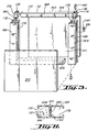
FIG. 4 is a partial sectional elevational view of the corners of a pair of adjacent panels in accordance with the invention. -
FIG. 5 is a perspective view of a corner of a display panel in accordance with the invention. -
FIG. 6 is an end view of an edge portion in accordance with the invention. -
FIG. 7 is a perspective view of a sliding connector in accordance with the invention.. -
FIG. 8 is a perspective view of a corner connector component in accordance with the invention. -
FIG. 9 is an elevational view of a corner connector in accordance with the invention. -
FIG. 10 is a cross-sectional view taken at line 10-10 ofFIG. 9 . -
FIG. 11 is a cross-sectional view at line 11-11 ofFIG. 9 . -
FIG. 12 is a perspective view of a vertical stacking connector in accordance with the invention. -
FIG. 13 is an elevational view of the connector ofFIG. 12 . -
FIG. 14 . is a perspective view of an alternative display in accordance with the invention. -
FIG. 15 is an elevation perspective view of an alternative display in accordance with the invention. -
FIG. 16 is a perspective view of a curved connector portion in accordance with the invention. -
FIG. 17 is a perspective view of a molding arrangement for producing display panels in accordance with the invention. - Referring to
FIG. 1 , a display system in accordance with the invention is illustrated and is designated with thenumeral 20. Said display system includes a plurality of individual panels 22 which may be generally rectangular and planar in shape as indicated by thepanel designation 24 or may have curved sections as represented by the panel enumerated 26. The display system is configured as adisplay 30 which may have a graphic design orindicia 36 as shown asFIG. 1 . Such displays typically require that thejuncture 40 between adjacent panels be completely closed to provide a continuous image of the graphics or indicia. Thedisplay 30 may also have poweredaccessories 40 illustrated as spotlights connected to or supported by thedisplay screen 34. Such accessories require power which is provided by the electric wires 44 illustrated by the dashed lines. Such electric wires will suitably be connected to a power outlet or suitable low-voltage power supply 48. - Referring to
FIGS. 2 ,3 , and4 , various aspects of the invention are illustrated.FIG. 2 illustrates afirst panel 72, asecond panel 73 and athird panel 74. Each panel has afront side 80, back side 82, aperiphery 84, a tophorizontal edge 86, bottomhorizontal edge 88, a leftvertical edge 92, a rightvertical edge 94, and fourcorners 100. - Located at the periphery or
perimeter 84 of each panel is an inwardly extending and outwardly facingrecess 110. Said recess is configured as an outwardly-facingchannel 112. The channel includesside walls base portion 120. -
FIG. 17 is a perspective view of a molding arrangement for producing display panels in accordance with the invention. - Referring to
FIG. 1 , a display system in accordance with the invention is illustrated and is designated with the numeral 20. Said display system includes a plurality of individual panels 22 which may be generally rectangular and planar in shape as indicated by thepanel designation 24 or may have curved sections as represented by the panel enumerated 26. The display system is configured as adisplay 30 which may have a graphic design orindicia 36 as shown asFIG. 1 . Such displays typically require that thejuncture 40 between adjacent panels be completely closed to provide a continuous image of the graphics or indicia. Thedisplay 30 may also have poweredaccessories 41 illustrated as spotlights connected to or supported by thedisplay screen 34. Such accessories require power which is provided by the electric wires 44 illustrated by the dashed lines. Such electric wires will suitably be connected to a power outlet or suitable low-voltage power supply 48. - Referring to
FIGS. 2 ,3 , and4 , various aspects of the invention are illustrated.FIG. 2 illustrates afirst panel 72, asecond panel 73 and athird panel 74. Each panel has afront side 80, back side 82, aperiphery 84, a tophorizontal edge 86, bottomhorizontal edge 88, a leftvertical edge 92, a rightvertical edge 94, and fourcorners 100. - Located at the periphery or
perimeter 84 of each panel is an inwardly extending and outwardly facingrecess 110. Said recess is configured as an outwardly-facingchannel 112. The channel includesside walls base portion 120. Positioned at the base on the left vertical edge and right vertical edge are a plurality of slidingconnectors 126. These connectors engage with corresponding cooperating connectors on like edges of adjacent panels by offsetting vertically one panel next to the other panel and vertically sliding the panels into alignment as illustrated by the dashed lines ofFIG. 2 with the numeral 130. - Positioned at the top horizontal edge at 86 and the bottom
horizontal edge 88 arevertical connector portions 136. Vertical connector portions connect stackingconnectors 140 that engage the connector portions of vertically adjacent panels such as the first and second panel ofFIG. 2 to connect same together. - The sliding connectors as shown in
FIG. 2 are ideally biased to assure that the adjacent perimeters of horizontally adjacent panels are in full contact without gaps. Such bias is preferably formed by integral plastic biasing elements as With regard to the vertically stacked panels, typically gravity will tightly secure same together and preclude any noticeable gaps between adjacent panels. - Referring specifically to
FIGS. 3 ,4 ,5 , and6 , details of the construction of a panel in accordance with the invention are illustrated. Thepanel framework 160 is comprised of a plurality of channelededge portions 164 including a pair of vertical channelededge portions 166 and a pair of horizontal channelededge portions 168. Said opposing pairs comprise high pressure laminate commonly known as Formica or may constitute material such as fabric, sheet metal, or foils. In certain embodiments no external panel or sheet material may be utilized and the panel may be formed with the fill material in the interior of the framework exposed. This type of configuration is suitable where differently colored exterior panels may stocked and may be attached to stockpiled display units as necessary for customer orders. - Referring to
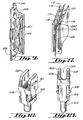
FIGS. 8, 9, 10, and 11 , details of the corner component are illustrated. The corner component is generally T-shaped as shown inFIG. 8 with alower leg 230 and a pair of alignedlegs lower leg 230 is sized for insertion into therecess 110 defined by the inwardly facing channel of the upper and lower horizontal channelededge portions 168, not shown in this view. The aligned upper legs of the T-shaped 232, 234 are inserted into each end of the inwardly facing channel of the vertical channelededge portions 166. The corner connectors have several significant structural features as follows. Ahook member 240 is configured to engage, lock and position a slidingconnector 126 at thecorresponding hook 242 of said connector. Theinterior leg 234 includes a interior taperedportion 256 which helps define atortuous air vent 262 that allows the injection of and/or expansion of the fill material, i.e. polyurethane foam, up to the corner piece and allows the escape of the displaced air but effectively clogs when the polyurethane reaches saidtortuous air vent 262. Theexterior leg 232 of the corner portion includes areceptacle 272 for receiving plug-in components 280 which may comprise stackingconnectors 140 oraccessory connectors 41, orfeet 43 comprise high pressure laminate commonly known as Formica or may constitute material such as fabric, sheet metal, or foils. In certain embodiments no external panel or sheet material may be utilized and the panel may be formed with the fill material in the interior of the framework exposed. This type of configuration is suitable where differently colored exterior panels may stocked and may be attached to stockpiled display units as necessary for customer orders. - Referring to
FIGS. 8, 9, 10, and 11 , details of the corner component are illustrated. The corner component is generally T-shaped as shown inFIG. 8 with alower leg 230 and a pair of alignedlegs lower leg 230 is sized for insertion into therecess 110 defined by the inwardly facing channel of the upper and lower horizontal channelededge portions 168, not shown in this view. The aligned upper legs of the T-shaped 232, 234 are inserted into each end of the inwardly facing channel of the vertical channelededge portions 166. The corner connectors have several significant structural features as follows. Ahook member 240 is configured to engage, lock and position a slidingconnector 126 at thecorresponding hook 242 of said connector. Theinterior leg 234 includes a interior taperedportion 256 which helps define atortuous air vent 262 that allows the injection of and/or expansion of the fill material, i.e. polyurethane foam, up to the corner piece and allows the escape of the displaced air but effectively clogs when the polyurethane reaches saidtortuous air vent 262. Theexterior leg 232 of the corner portion includes areceptacle 272 for receiving plug-in components which may comprise stackingconnectors 140 oraccessory connectors 41, orfeet 43 some flex to thefinger portion 322 which includedetents 324. The plug-in components can utilize various other configured upper portions that, for example, would not plug in to an adjacent panel but rather would attach to or be part of an accessory such as thespotlights 40 shown inFIG. 1 . - The corner connectors are preferably formed of die-cast zinc or zinc alloy, but may also be formed of other materials such as glass or fiber-filled nylon. Similarly, the plug-in components may be die-cast or made of glass or fiber-filled nylon or other thermoplastics.
- The
air vent 262 having the tortuous path, may have various is configurations. As illustrated, it may be formed by structure in the corner component. Referring toFIG. 4 , alternate vents such as use of plugs 335 in apertures 336 formed of sintered beads. The important characteristic of the vent is that it is substantially pervious to the escape of air from the filling or expanding of the fill material and is substantially impervious to the passage of the fill material. - Referring to
FIGS. 14 and 15 , two additionalportable displays FIG. 16 illustrates acurved connector portion 520, suitable for use in the curved panel section ofFIG. 14 . Such a curved connector portion may preferably be unitarily formed by injection molding of thermoplastic material. The component includes twocorner connector portions cutaway portions 530 which provide the wire management aspect of the invention are provided as well asstructure 534 to provide a tortuous vent. Theedge portion 540 may be channel shaped and has a plurality of intermediatestructural supports 544 each which haswire management openings 548. Such structural supports provide strength and rigidity to the component. - Referring to
FIG. 17 , ageneric press 500 is illustrated to aid in description of the methodology of forming the panels. Theframework 160, including theedge portions 164 and thecorner components 176, are placed in a press with thepaneler sheet members 206 if desired. The press is closed and polyurethane expanding foam is injected by atool 502 from asupply source 504. The foam core is allowed to cure sufficiently to avoid any further expansion and is then removed from the press. Theinjection tool 502 may be suitably through an aperture in one of the edge portions. During said injection,appropriate vents 508 are provided in the press and are ideally located at the corners such that air that passes through the tortuous air vent at thecorner connector components 176 may be readily discharged. - The skilled person will appreciate that variation of the disclosed arrangements are possible without departing from the invention. Accordingly, the above description of several embodiments is made by way of example and not for the purposes of limitation.
Claims (11)
- A display system comprised of a plurality of rectangular shaped panels (22) each of which has a front side (80), a back side (82), and four edges (86, 88, 92, 94), the panels (22) coupleable and directly attributable together at their edges (86, 88, 92, 94) forming a display (20) with, each panel (22) having a top horizontal edge (86), a bottom horizontal edge (88), a left vertical edge (92) and a right vertical edge (94) defining a periphery (84), and a panelar sheet (210), characterized in that:the panelar sheet (210) spans the front side (80) of each panel (22) and extends to the periphery (84) of each of said panels (22), at least one edge of each panel (22) having a recess (110) forming an outwardly facing channel (112), extending inwardly into said edge, extending the length of said edge and defining a wire conduit, whereby the recess (110) is exposed substantially the length of said edge when the panel (22) is not coupled with another panel (22) at said edge and whereby said recess (110) is substantially concealed the length of said edge when the panel (22) is coupled with another panel (22) at said edge, a wire (44) providing power to a powered accessory (40), the wire (44) placeable in the recess (110) thereby concealing the wire (44) when the panel (22) is coupled with another panel (22).
- The display system of claim 1, characterized in that each panel (22) couples with another panel (22) at the edge with recess (110) by way of a plurality of connectors (126, 140) extending between said panels (22), and wherein said connectors (126, 140) extend within said recess (110), whereby when said edge of said panel (22) is not coupled with another panel (22), said plurality of connectors (126, 140) are exposed and whereby when said edge of said panel (22) is coupled with another panel (22), said connectors (126, 140) are concealed from the front side (80) and the back side (82).
- The display system of claim 2 characterized in that each of said connectors (126, 140) has an opening (206, 314) whereby said wire conduit is continued past said connector (126, 140).
- The display system of claim 2 characterized in that the recess (110) defines a channel (112) with an interior width and wherein the wire conduit has a diameter and said diameter is at least 1/5 the width of channel (112) along the length of said recess (110).
- The display system of claim 1, characterized in that each of the channeled edge portions (164) have a recess (182) inwardly positioned with respect to the outwardly facing channel (112) the inwardly positioned recesses (182) are sized and positioned for engagement with a respective corner component (176).
- The display system of claim 5, characterized in that each of the inwardly positioned recesses (182) of vertical channeled portions (166) comprise an inwardly facing channel (178) and wherein each of the corner components (176) comprises a vertically extending portion (232, 234) sized to fit the inwardly facing channel (178) of the respective vertical channeled portion (166).
- The display system of claim 5, characterized in that each of the inwardly positioned recesses (110) of horizontal channeled portions (168) comprise an inwardly facing channel (182) and wherein each of the corner components (176) comprises a horizontally extending portion (230) sized to fit the inwardly facing channel (182) of the respective horizontal channeled portion (168).
- The display system of claim 1, further comprising a plurality of vertical stacking connectors (140) for removeable connecting between vertically stacked display panels (22), each vertical stacking connector (140) having an opening (314) defining a wire conduit extends therethrough, each vertical stacking connector (140) allowing adjacent horizontal channeled edge portions (168) of adjacent stacked display panels (22) to abut against one another whereby a wire conduit extending along and inside of each of the outwardly facing channels (112), wherein each vertical stacking connector (140) has two ends and each end connectable to corner components (176) of the display panels (22) and wherein at least one connector end of each panel stacking connector display system further comprises a U-shaped portion to preserve the wire conduit at the corner portion where the stacking connector (140) is used.
- The display system of claim 1, wherein the plurality of rectangular shaped panels comprises a first display panel (72) and a second display panel (73), characterized in that:the first display panel (72) and the second display panel (73) are directly abutting and coupled one on top of the other, at least one removeable connector (140) extending vertically between the first and second display panels (72, 73) coupling the top horizontal edge (86) of the first display panel (72) to the bottom horizontal edge (88) of the second display panel (73), a channel (112) extending along at least one of the top horizontal edge (86) of the first display panel (72) and the bottom horizontal edge (88) of the second display panel (74), the channel (112) defining a horizontal wire conduit, the at least one removable connector (140) being positioned within the channel (112), the connector (140) having a wire conduit opening (314) extending horizontally thereby continuing the wire conduit past the at least one connector (140) whereby the wire conduit runs from the right vertical edges (94) to the left vertical edges (92) of the first and second display panels (72, 73).
- The display system of claim 9 further comprising a third display panel (74) connected horizontally adjacent to and abutted against one of the first and second display panels (72, 73) that are coupled one on the top of the other, at least two connectors (126) vertically spaced from one another extending horizontally between the third panel (74) and the one of the first and second panels (72, 73), a channel (178) extending along the vertical edge (92, 94) of at least one of the third panel (74) and the one of the first and second panels (72, 73) defining a vertical wire conduit, each of the two connectors (126) having a vertically extending opening (206) whereby the vertical wire conduit continues therethough, the wire (44) extending through the vertical wire conduit and past the two connectors (126), the wire (44) being concealed therein.
- The display system of claim 10, wherein the first display panel (72), second display panel (73), and the third display panel (74) meet at a corner juncture and wherein the vertical wire conduit is in communication with the horizontal conduit at the corner juncture thereby providing a wire conduit extending vertically and horizontally and wherein the wire (44) extends vertically and horizontally therethrough, the wire (44) concealed therein.
Applications Claiming Priority (3)
| Application Number | Priority Date | Filing Date | Title |
|---|---|---|---|
| US09/556,381 US6536147B1 (en) | 2000-04-24 | 2000-04-24 | Panel display system with wire management |
| US556381 | 2000-04-24 | ||
| PCT/US2001/013170 WO2001084526A1 (en) | 2000-04-24 | 2001-04-24 | Panel display system with wire management |
Publications (3)
| Publication Number | Publication Date |
|---|---|
| EP1297518A1 EP1297518A1 (en) | 2003-04-02 |
| EP1297518A4 EP1297518A4 (en) | 2005-01-26 |
| EP1297518B1 true EP1297518B1 (en) | 2009-03-25 |
Family
ID=24221114
Family Applications (1)
| Application Number | Title | Priority Date | Filing Date |
|---|---|---|---|
| EP01928798A Expired - Lifetime EP1297518B1 (en) | 2000-04-24 | 2001-04-24 | Panel display system with wire management |
Country Status (6)
| Country | Link |
|---|---|
| US (1) | US6536147B1 (en) |
| EP (1) | EP1297518B1 (en) |
| AU (1) | AU2001255615A1 (en) |
| CA (1) | CA2416031C (en) |
| DE (1) | DE60138101D1 (en) |
| WO (1) | WO2001084526A1 (en) |
Families Citing this family (24)
| Publication number | Priority date | Publication date | Assignee | Title |
|---|---|---|---|---|
| ITMI20020771A1 (en) * | 2002-04-10 | 2003-10-10 | Unifor Spa | MODULAR STRUCTURE FOR MODULAR DIVIDING WALLS FORMED BY JUST-PLACED PANELS |
| GB0300918D0 (en) * | 2003-01-15 | 2003-02-12 | Urban Jackson Sean P D | Multi-functional display panel combining interlocking panel couplings |
| US6854233B2 (en) * | 2003-05-28 | 2005-02-15 | Hon Technology Inc. | Quick-connect panel system |
| US20070052709A1 (en) * | 2005-09-07 | 2007-03-08 | Randy Pender | Display system |
| KR100719658B1 (en) * | 2005-11-17 | 2007-05-17 | 삼성에스디아이 주식회사 | Portable display |
| US20080053003A1 (en) * | 2006-08-31 | 2008-03-06 | Hockemeyer Timothy J | Roof system for emergency isolation and treatment shelter (EITS) |
| USD586480S1 (en) | 2006-08-31 | 2009-02-10 | Serenus Johnson Portables, Llc | Wall column |
| USD586438S1 (en) | 2006-08-31 | 2009-02-10 | Serenus Johnson Portables, Llc | Wall cap |
| US20080053017A1 (en) * | 2006-08-31 | 2008-03-06 | Hockemeyer Timothy J | Rigid wall assembly for emergency isolation and treatment shelter (EITS) |
| USD586927S1 (en) | 2006-08-31 | 2009-02-17 | Serenus Johnson Portables, Llc | Center purlin |
| US7698860B2 (en) | 2006-08-31 | 2010-04-20 | Stageright Corporation | Raised deck system for emergency isolation and treatment shelter (EITS) |
| US20080053032A1 (en) * | 2006-08-31 | 2008-03-06 | Hockemeyer Timothy J | Support column system for emergency isolation and treatment shelter (EITS) |
| USD586479S1 (en) | 2006-08-31 | 2009-02-10 | Serenus Johnson Portables, Llc | Intermediate purlin |
| WO2008150717A2 (en) * | 2007-06-01 | 2008-12-11 | Steelcase Development Corporation | Work space arrangements including counter assembly |
| US9185974B2 (en) | 2010-06-02 | 2015-11-17 | Steelcase Inc. | Frame type workstation configurations |
| USD662649S1 (en) * | 2010-07-16 | 2012-06-26 | C.S.A. Photonics Limited | Lighting projector |
| US8601729B2 (en) * | 2011-01-21 | 2013-12-10 | Rose Displays, Ltd. | Modular panel display arrangement |
| FR2976602B1 (en) * | 2011-06-20 | 2019-06-14 | Matondo Wansulama | EQUIPPED PARK, MONOBLOC, AUTO CARRIED BY WHEELS, HAVING MANUAL MOBILITY OR REMOTE CONTROL, SUPPORTING A SCREEN AND EQUIPPED WITH AN EQUIPPED FITTING OF ELECTRICAL CONNECTIONS AND NETWORK |
| US8601730B2 (en) * | 2012-07-31 | 2013-12-10 | Nexxtshow Exposition Services Llc | Tradeshow display system |
| US12376677B1 (en) | 2012-10-10 | 2025-08-05 | Steelcase Inc. | Ergonomic seating system, tilt-lock control and remote powering method and apparatus |
| US9051079B2 (en) * | 2012-10-19 | 2015-06-09 | Shenzhen China Star Optoelectronics Technology Co., Ltd. | Pallet |
| DE202014100622U1 (en) * | 2014-02-12 | 2015-05-15 | Michael Linden | Presentation furniture for goods |
| US10517392B2 (en) | 2016-05-13 | 2019-12-31 | Steelcase Inc. | Multi-tiered workstation assembly |
| WO2017197395A1 (en) | 2016-05-13 | 2017-11-16 | Steelcase Inc. | Multi-tiered workstation assembly |
Family Cites Families (59)
| Publication number | Priority date | Publication date | Assignee | Title |
|---|---|---|---|---|
| US2962407A (en) | 1955-11-07 | 1960-11-29 | Monsanto Chemicals | Method for preparing laminated foam structures |
| US3090078A (en) | 1958-05-29 | 1963-05-21 | A M Stackhouse | Process for foaming panels in situ |
| US3161911A (en) | 1962-10-02 | 1964-12-22 | Foam Products Corp | Mold for foamed panels and the like |
| US3410931A (en) | 1963-10-11 | 1968-11-12 | Alside Inc | Method and apparatus for making laminated panels of polystyrene foam and aluminum |
| US3389196A (en) | 1964-07-24 | 1968-06-18 | Stahl Ind Inc | Method of making an insulated core building panel |
| US3560285A (en) | 1967-02-06 | 1971-02-02 | Kaiser Aluminium Chem Corp | Processes for producing composite panels |
| US3630819A (en) | 1968-09-23 | 1971-12-28 | Goodyear Tire & Rubber | Foamed polyurethane laminates |
| US3589755A (en) | 1969-06-20 | 1971-06-29 | Harold M King | Prefabricated-wall attachment system |
| US3668031A (en) | 1970-03-03 | 1972-06-06 | Bethlehem Steel Corp | Method of making foam core sandwich panel |
| US3834967A (en) | 1971-04-30 | 1974-09-10 | Control Building Syst Inc | Apparatus for forming foamed panels |
| US3777435A (en) | 1971-11-15 | 1973-12-11 | American Velcro Inc | Attachment assembly |
| US3826206A (en) | 1972-10-12 | 1974-07-30 | Directional Ind Inc | Modular furniture or like articles and modular units therefor |
| US3959050A (en) | 1974-07-15 | 1975-05-25 | John C. Gurche | Plaque board with polyurethane core and method for construction same |
| GB1470066A (en) | 1974-10-08 | 1977-04-14 | Ici Ltd | Laminates |
| US4036923A (en) | 1975-03-03 | 1977-07-19 | Exxon Research And Engineering Company | Method for forming large reinforced foamed plastic panels |
| US4437275A (en) | 1979-06-04 | 1984-03-20 | Nomadic Structures, Inc. | Collapsible self-supporting structures |
| DE2942413A1 (en) | 1979-10-19 | 1981-05-07 | Lentia GmbH Chem. u. pharm. Erzeugnisse - Industriebedarf, 8000 München | METHOD AND DEVICE FOR THE CONTINUOUS PRODUCTION OF SINGLE OR MULTILAYER, REINFORCED RAILS FROM HEAT-CURABLE PLASTIC |
| US4480715A (en) | 1981-03-30 | 1984-11-06 | Brooks George E | Sight and sound barrier |
| US4462196A (en) | 1981-06-18 | 1984-07-31 | P.C. Freiberg Pty. Ltd. | Means for interconnecting panels |
| US4438166A (en) | 1983-02-04 | 1984-03-20 | The Celotex Corporation | Structural laminate and method for making same |
| US4712336A (en) | 1983-04-18 | 1987-12-15 | Backer Bruce E | Interconnecting "full bleed" modular panel and connective hardware system to form a variety of exhibit and office interior enclosures |
| US4493748A (en) | 1984-01-06 | 1985-01-15 | Cross Carroll N | Process of making raised line imprinted display mounts |
| DE3429640A1 (en) * | 1984-08-11 | 1986-02-20 | Uwe 4930 Detmold Dorn | MOBILE WALL |
| GB8510909D0 (en) * | 1985-04-30 | 1985-06-05 | Vickers Plc | Office screens & partitions |
| US4727994A (en) | 1985-10-28 | 1988-03-01 | Skyline Displays, Inc. | Collapsible support and attachment structure |
| US4716698A (en) * | 1986-06-06 | 1988-01-05 | Haworth, Inc. | Wall system with split pole for lay-in wiring |
| US4726973A (en) | 1987-03-02 | 1988-02-23 | Thompson Gerald M | Laminated subdividable panel |
| US4823858A (en) | 1987-06-02 | 1989-04-25 | Nimlok Company | Portable display panel and hinge system |
| US5089189A (en) | 1988-04-08 | 1992-02-18 | Centrite Corp. | Process for reinforced polymeric composites |
| US4828897A (en) | 1988-04-08 | 1989-05-09 | Centrite Corporation | Reinforced polymeric composites |
| US4967531A (en) | 1988-12-05 | 1990-11-06 | Lippert Holding Company | Wall partition units |
| US5295342A (en) | 1989-11-22 | 1994-03-22 | Bonnie Roche | Display panel having dual securement means |
| US5069263A (en) | 1990-02-08 | 1991-12-03 | Hon Industries, Inc. | Panel interlock system |
| DK0454059T3 (en) | 1990-04-23 | 1995-10-09 | Nippon Zeon Co | Shaped composite objects |
| US5114510A (en) | 1990-09-26 | 1992-05-19 | Wright John T | Method of forming a lightweight structural panel |
| US5097643A (en) | 1990-12-19 | 1992-03-24 | Wittler Waldemar E | Interlocking structural members with edge connectors |
| EP0563276A1 (en) | 1990-12-19 | 1993-10-06 | WITTLER, Waldemar E. | Interlocking structural members with edge connectors |
| US5092385A (en) | 1991-06-21 | 1992-03-03 | Skyline Displays, Inc. | Interlocking panel system |
| US5318734A (en) | 1992-06-09 | 1994-06-07 | Michael Palmersten | Thin urethane panels having double acting hinge |
| US5325649A (en) | 1992-07-07 | 1994-07-05 | Nikken Seattle, Inc. | Easily-assembled housing structure and connectors thereof |
| US5295341A (en) | 1992-07-10 | 1994-03-22 | Nikken Seattle, Inc. | Snap-together flooring system |
| US5472365A (en) | 1993-05-17 | 1995-12-05 | Engel; Richard J. | Polygon attachment system for constructing polyhedra |
| US5343665A (en) | 1993-06-28 | 1994-09-06 | Ramp R & D | Cabana panels having adjustable-strength interlocking means |
| US5537766A (en) * | 1994-02-17 | 1996-07-23 | Classic Exhibits Inc. | Trade show display panels and display panel systems and methods for interconnecting the display panel systems |
| US5502939A (en) | 1994-07-28 | 1996-04-02 | Elite Panel Products | Interlocking panels having flats for increased versatility |
| DE4431755C2 (en) | 1994-09-06 | 2000-05-25 | Biotec Biolog Naturverpack | Starch foam sandwich panel |
| US5642557A (en) | 1994-09-09 | 1997-07-01 | C J Distributors Limited | Panel display system |
| US5626926A (en) | 1994-10-12 | 1997-05-06 | Lin Pac, Inc. | Stand-alone decorative assembly |
| US5546720A (en) | 1995-03-10 | 1996-08-20 | Color & Design Exhibits | Panel assembly system |
| US5561960A (en) | 1995-04-18 | 1996-10-08 | The Exhibit House, Inc. | Modular wall panel system |
| US5685113A (en) * | 1995-06-05 | 1997-11-11 | Knoll, Inc. | Lay-in wireways for a space divider system |
| US5882776A (en) | 1996-07-09 | 1999-03-16 | Sentinel Products Corp. | Laminated foam structures with enhanced properties |
| US5921047A (en) | 1997-03-24 | 1999-07-13 | Walker; Marshall P. | Building structure having prefabricated interfitting structural parts |
| US5857304A (en) | 1997-04-07 | 1999-01-12 | Abex Display Systems | Slidable locking system for disengageable panels |
| US5916672A (en) | 1997-04-25 | 1999-06-29 | Brunswick Corporation | Thermoplastic multi-layer composite structure |
| US5970675A (en) | 1997-12-05 | 1999-10-26 | James D. Wright | Modular panel assembly |
| US5974713A (en) * | 1998-06-22 | 1999-11-02 | Wu; Shiang-Lan | Picture frame assembly |
| US6047509A (en) * | 1998-08-07 | 2000-04-11 | Media/Graphics, Inc. | Corner support for panel frames |
| US6253509B1 (en) * | 1999-08-13 | 2001-07-03 | Teknion Furniture Systems Limited | Workspace partition system |
-
2000
- 2000-04-24 US US09/556,381 patent/US6536147B1/en not_active Expired - Fee Related
-
2001
- 2001-04-24 DE DE60138101T patent/DE60138101D1/en not_active Expired - Lifetime
- 2001-04-24 WO PCT/US2001/013170 patent/WO2001084526A1/en not_active Ceased
- 2001-04-24 AU AU2001255615A patent/AU2001255615A1/en not_active Abandoned
- 2001-04-24 EP EP01928798A patent/EP1297518B1/en not_active Expired - Lifetime
- 2001-04-24 CA CA2416031A patent/CA2416031C/en not_active Expired - Fee Related
Also Published As
| Publication number | Publication date |
|---|---|
| DE60138101D1 (en) | 2009-05-07 |
| US6536147B1 (en) | 2003-03-25 |
| WO2001084526A1 (en) | 2001-11-08 |
| CA2416031A1 (en) | 2001-11-08 |
| AU2001255615A1 (en) | 2001-11-12 |
| CA2416031C (en) | 2010-03-30 |
| EP1297518A1 (en) | 2003-04-02 |
| EP1297518A4 (en) | 2005-01-26 |
Similar Documents
| Publication | Publication Date | Title |
|---|---|---|
| US6543164B1 (en) | Panel display system | |
| US6536147B1 (en) | Panel display system with wire management | |
| US4712336A (en) | Interconnecting "full bleed" modular panel and connective hardware system to form a variety of exhibit and office interior enclosures | |
| EP0653739B1 (en) | Modular sign system | |
| US11661736B2 (en) | Modular wall panels and system | |
| US8641155B2 (en) | Modular furniture system | |
| US5890607A (en) | Modular display | |
| EP2230659B1 (en) | Configurable panel display | |
| US4403554A (en) | Portable exhibit system | |
| US10729237B2 (en) | Configurable and dismantlable display case system comprising a plastic shelving unit with trays at different levels, and method of assembly | |
| CA2098275A1 (en) | Interlocking structural members with edge connectors | |
| US11666159B2 (en) | Configurable and dismantlable display case system and method of assembly | |
| US10854119B2 (en) | Display unit | |
| EP4046699B1 (en) | Puzzle case with mounting accessories | |
| US11085182B2 (en) | Modular wall panels and system | |
| US11373557B2 (en) | Frame assembly for displaying a tensionable textile media | |
| US6173536B1 (en) | Workstation | |
| US20080080930A1 (en) | Construction System For Seamlessly Adjoining Panels | |
| CA3154994A1 (en) | Modular wall panels and system | |
| US20010009346A1 (en) | Informative cardboard kiosk structure | |
| GB2546477A (en) | Exhibition system | |
| US7377060B1 (en) | Device and method for display of information | |
| JPS63501967A (en) | Partition wall device |
Legal Events
| Date | Code | Title | Description |
|---|---|---|---|
| PUAI | Public reference made under article 153(3) epc to a published international application that has entered the european phase |
Free format text: ORIGINAL CODE: 0009012 |
|
| 17P | Request for examination filed |
Effective date: 20021122 |
|
| AK | Designated contracting states |
Kind code of ref document: A1 Designated state(s): AT BE CH CY DE DK ES FI FR GB GR IE IT LI LU MC NL PT SE TR |
|
| AX | Request for extension of the european patent |
Extension state: AL LT LV MK RO SI |
|
| RAP1 | Party data changed (applicant data changed or rights of an application transferred) |
Owner name: SKYLINE DISPLAYS, INC. |
|
| RBV | Designated contracting states (corrected) |
Designated state(s): AT BE CH CY DE ES GB IT LI |
|
| RIN1 | Information on inventor provided before grant (corrected) |
Inventor name: GIMPEL, DIXON Inventor name: COTA, TIMOTHY Inventor name: SPERL, PAUL, N. Inventor name: FUNK, WILLIAM |
|
| A4 | Supplementary search report drawn up and despatched |
Effective date: 20041214 |
|
| RIC1 | Information provided on ipc code assigned before grant |
Ipc: 7G 09F 7/00 A Ipc: 7H 02G 3/28 B Ipc: 7E 04B 2/74 B Ipc: 7E 04C 2/52 B Ipc: 7G 09F 15/00 B |
|
| 17Q | First examination report despatched |
Effective date: 20061108 |
|
| GRAP | Despatch of communication of intention to grant a patent |
Free format text: ORIGINAL CODE: EPIDOSNIGR1 |
|
| RBV | Designated contracting states (corrected) |
Designated state(s): DE ES GB IT |
|
| RIC1 | Information provided on ipc code assigned before grant |
Ipc: G09F 15/00 20060101ALI20080924BHEP Ipc: E04B 2/74 20060101ALI20080924BHEP Ipc: G09F 7/00 20060101AFI20080924BHEP Ipc: E04C 2/52 20060101ALI20080924BHEP |
|
| GRAS | Grant fee paid |
Free format text: ORIGINAL CODE: EPIDOSNIGR3 |
|
| GRAA | (expected) grant |
Free format text: ORIGINAL CODE: 0009210 |
|
| AK | Designated contracting states |
Kind code of ref document: B1 Designated state(s): DE ES GB IT |
|
| REG | Reference to a national code |
Ref country code: GB Ref legal event code: FG4D |
|
| REF | Corresponds to: |
Ref document number: 60138101 Country of ref document: DE Date of ref document: 20090507 Kind code of ref document: P |
|
| PG25 | Lapsed in a contracting state [announced via postgrant information from national office to epo] |
Ref country code: ES Free format text: LAPSE BECAUSE OF FAILURE TO SUBMIT A TRANSLATION OF THE DESCRIPTION OR TO PAY THE FEE WITHIN THE PRESCRIBED TIME-LIMIT Effective date: 20090706 |
|
| PLBE | No opposition filed within time limit |
Free format text: ORIGINAL CODE: 0009261 |
|
| STAA | Information on the status of an ep patent application or granted ep patent |
Free format text: STATUS: NO OPPOSITION FILED WITHIN TIME LIMIT |
|
| 26N | No opposition filed |
Effective date: 20091229 |
|
| PGFP | Annual fee paid to national office [announced via postgrant information from national office to epo] |
Ref country code: DE Payment date: 20100428 Year of fee payment: 10 |
|
| PGFP | Annual fee paid to national office [announced via postgrant information from national office to epo] |
Ref country code: GB Payment date: 20100426 Year of fee payment: 10 |
|
| PG25 | Lapsed in a contracting state [announced via postgrant information from national office to epo] |
Ref country code: IT Free format text: LAPSE BECAUSE OF FAILURE TO SUBMIT A TRANSLATION OF THE DESCRIPTION OR TO PAY THE FEE WITHIN THE PRESCRIBED TIME-LIMIT Effective date: 20090325 |
|
| GBPC | Gb: european patent ceased through non-payment of renewal fee |
Effective date: 20110424 |
|
| PG25 | Lapsed in a contracting state [announced via postgrant information from national office to epo] |
Ref country code: DE Free format text: LAPSE BECAUSE OF NON-PAYMENT OF DUE FEES Effective date: 20111101 |
|
| PG25 | Lapsed in a contracting state [announced via postgrant information from national office to epo] |
Ref country code: GB Free format text: LAPSE BECAUSE OF NON-PAYMENT OF DUE FEES Effective date: 20110424 |
|
| REG | Reference to a national code |
Ref country code: DE Ref legal event code: R119 Ref document number: 60138101 Country of ref document: DE Effective date: 20111101 |