EP1296534A2 - Modular bass array - Google Patents
Modular bass array Download PDFInfo
- Publication number
- EP1296534A2 EP1296534A2 EP02102315A EP02102315A EP1296534A2 EP 1296534 A2 EP1296534 A2 EP 1296534A2 EP 02102315 A EP02102315 A EP 02102315A EP 02102315 A EP02102315 A EP 02102315A EP 1296534 A2 EP1296534 A2 EP 1296534A2
- Authority
- EP
- European Patent Office
- Prior art keywords
- module
- audio
- parameter value
- bass
- audio signals
- Prior art date
- Legal status (The legal status is an assumption and is not a legal conclusion. Google has not performed a legal analysis and makes no representation as to the accuracy of the status listed.)
- Granted
Links
Images


Classifications
-
- H—ELECTRICITY
- H04—ELECTRIC COMMUNICATION TECHNIQUE
- H04R—LOUDSPEAKERS, MICROPHONES, GRAMOPHONE PICK-UPS OR LIKE ACOUSTIC ELECTROMECHANICAL TRANSDUCERS; ELECTRIC HEARING AIDS; PUBLIC ADDRESS SYSTEMS
- H04R3/00—Circuits for transducers
- H04R3/12—Circuits for transducers for distributing signals to two or more loudspeakers
-
- H—ELECTRICITY
- H04—ELECTRIC COMMUNICATION TECHNIQUE
- H04R—LOUDSPEAKERS, MICROPHONES, GRAMOPHONE PICK-UPS OR LIKE ACOUSTIC ELECTROMECHANICAL TRANSDUCERS; ELECTRIC HEARING AIDS; PUBLIC ADDRESS SYSTEMS
- H04R1/00—Details of transducers, loudspeakers or microphones
- H04R1/20—Arrangements for obtaining desired frequency or directional characteristics
- H04R1/32—Arrangements for obtaining desired frequency or directional characteristics for obtaining desired directional characteristic only
- H04R1/40—Arrangements for obtaining desired frequency or directional characteristics for obtaining desired directional characteristic only by combining a number of identical transducers
- H04R1/403—Arrangements for obtaining desired frequency or directional characteristics for obtaining desired directional characteristic only by combining a number of identical transducers loud-speakers
-
- H—ELECTRICITY
- H04—ELECTRIC COMMUNICATION TECHNIQUE
- H04R—LOUDSPEAKERS, MICROPHONES, GRAMOPHONE PICK-UPS OR LIKE ACOUSTIC ELECTROMECHANICAL TRANSDUCERS; ELECTRIC HEARING AIDS; PUBLIC ADDRESS SYSTEMS
- H04R5/00—Stereophonic arrangements
- H04R5/02—Spatial or constructional arrangements of loudspeakers
Definitions
- This invention relates to audio bass arrays, and more particularly to modular bass arrays.
- an audio loudspeaker array system includes a first speaker module, and a second speaker module, constructed and arranged to radiate sound waves responsive to audio signals.
- the sound waves radiated by the first speaker module and the sound waves radiated by the second speaker module combine to form a radiation pattern.
- the audio array further includes a positioning system, for positioning the first bass module relative to the second bass module at one a plurality of fixed predetermined distances, an audio signal input terminal electronically for coupling the loudspeaker array to a source of the audio signals for receiving the audio signals, and an audio signal processing device, electronically coupling the audio signal input terminal to the first bass module and to the second bass module.
- the audio signal processor processes the audio signals and transmits the audio signals to the first speaker module and to the second loudspeaker module.
- the audio signal processing device is constructed and arranged to apply a first signal processing parameter value to the audio signals transmitted to the first loudspeaker module and a second signal processing parameter value to the audio signals transmitted to the second loudspeaker module so that the first parameter value and the second parameter value differ by a parameter value difference.
- the audio loudspeaker further includes a processing parameter selection device, comprising a plurality of preset indicators, each of the preset indicators corresponding to a predetermined parameter value difference.
- the predetermined parameter value difference and a one of the plurality of predetermined distances correspond to a predetermined radiation pattern.
- an audio loudspeaker array in another aspect of the invention, includes a first module comprising an electro-acoustical transducer and an enclosure having a width a depth and a height, a second module comprising a loudspeaker and an enclosure, and a positioner for positioning the first module at a fixed distance from the second module, wherein the fixed distance is greater than twice the smallest of the width, the depth and the height.
- a source of bass audio signals (hereinafter audio signal source) 10, such as a mixer, is coupled to audio signal processor 12.
- Audio signal processor 12 is coupled to bass array 16, through amplifier 14.
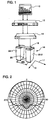
- Bass array 16 includes first bass module 22-1 and second bass module 22-2, which are held in a horizontally displaced position relative to each other by brackets 18 and 20.
- Audio signal source 10 may be a conventional professional mixer.
- System controller 12 may be a Panaray ® System Digital Controller, available commercially from Bose Corporation of Framingham, Massachusetts.
- Amplifier 14 may be a conventional amplifier with at least two input terminals and at least two output terminals.
- Bass modules 22-1 and 22-2 may be Panaray ® MB4 Modular Bass Loudspeakers (each of which comprise four 15 cm (six inch) drivers, which have enclosure dimensions of 38.1 cm (15.0 inches) deep by 22.9 cm (9.0 inches) wide by 66.0 cm (26.0 inches) high, and which are substantially omni-directional below 300 Hz), and brackets 18 and 20 may be MB4 Endfire 2X Bass Array Brackets, all available commercially from Bose Corporation of Framingham, Massachusetts.
- Panaray ® MB4 Modular Bass Loudspeakers each of which comprise four 15 cm (six inch) drivers, which have enclosure dimensions of 38.1 cm (15.0 inches) deep by 22.9 cm (9.0 inches) wide by 66.0 cm (26.0 inches) high, and which are substantially omni-directional below 300 Hz
- brackets 18 and 20 may be MB4 Endfire 2X Bass Array Brackets, all available commercially from Bose Corporation of Framingham, Massachusetts.
- audio signal source transmits audio signals to audio signal processor 12.
- Audio signal processor 12 decodes the audio signals to produce processed audio signal, which may include a bass audio signal.
- Audio signal processor outputs the bass audio signal as two channels, with different signal processing parameter values applied to the two channels.
- Parameters for which different processing values may be applied include magnitude equalization, phase equalization, time delay, phase, and magnitude, or some combination of those parameters.
- the invention will be described using time delay as the parameter for which different values are applied to the two channels. Different values (which may be zero) of time delay can be applied to the two channels so that the two channels are separated in time by time delay ⁇ T.
- Amplifier 14 amplifies the two channels or bass audio signals and outputs the amplified audio signals to bass modules 22-1 and 22-2, still separated in time by time delay ⁇ T.
- Bass modules 22-1 and 22-2 transduce the audio signals to sound waves.
- the resultant sound field is shown in FIG. 2, with zero degree represented by direction 17 connecting the acoustical centers of bass modules 22-1 and 22-2 and 90 degrees represented by direction 19, orthogonal to direction 17 in the horizontal plane.
- FIG. 2 there is shown a polar plot showing the radiation pattern taken at 160 Hz of the audio system of FIG. 1, with a time delay ⁇ T of 1.71ms, a center to center distance d between bass modules of 58.4 cm (23 inches), which is greater than half the shortest wavelength intended to be reproduced (300Hz, wavelength of about 115.8 cm (3.8 feet)) and more than twice the width (the smallest linear dimension) of the enclosure.
- the radiation pattern is determined principally by the distance d between the bass modules and by the value of time delay ⁇ T. If one or both of the bass modules are not omni-directional, the radiation pattern may also be affected by the relative orientation of the bass modules. If the bass modules are directional in the frequency range radiated, brackets 18 and 20 may be adapted to fix the orientation or the two modules, as well as fixing the spacing.
- the value of time delay ⁇ T may be entered by manually or, more conveniently through the use of preset indicators on system controller 12.
- one of the preset indicators is pre-programmed to delay the audio signal to bass module 22-1 relative to the audio signal to bass module 22-2 so that the radiation responsive to the audio signal from bass module 22-2 is radiated 1.7a ms. later than the corresponding radiation from bass module 22-1.
- a user desires a maximum acoustic output as of 116 dB SPL, with a radiation pattern as shown in fig. 2, the user can assemble a bass array as shown in fig. 1, and select a preset setting.
- Preset indicator may be selected by entering the "Preset" button 30 and the up and down indicators, 32 and 34 respectively.
- Other system controllers may have different preset selector arrangements, such as discrete programmable manual pushbuttons, touch screens, or display screens using selector indicators such as computer mouses.
- An audio system according to the invention is advantageous because it provides a bass array that can radiate a predetermined radiation pattern with less setup time than conventional bass arrays.
- a bass array according to the invention is particularly advantageous for sound systems for portable applications that must provide high amounts of acoustic output, and must be set up quickly.
- the components of the array can be transported and stored separately.
- the array can be assembled in the correct physical configuration quickly, and the correct time delay can be input easily and without the user having to record or memorize the appropriate time delay interval.
- a source of bass audio signals (hereinafter audio signal source) 10, such as a mixer, is coupled to audio signal processor 12.
- Audio signal processor 12 is coupled to bass array 16', through amplifiers 14-1 and 14-2.
- Bass array 16' includes first bass module 22-1 second bass module 22-2, third bass module 22-3, and fourth bass module 22-4, which are held in position in a horizontal line relative to each other by brackets 18' and 20'.
- Audio signal source 10 may be a conventional professional mixer.
- System controller 12 may be a Panaray ® System Digital Controller, available commercially from Bose Corporation of Framingham, Massachusetts.
- Amplifiers 14-1 and 14-2 may be conventional amplifiers with at least two input terminals and at least two output terminals.
- Bass modules 22-1, 22-2, 22-3, and 22-4 may be Panaray ® MB4 Modular Bass Loudspeakers (which are substantially omni-directional below 300 Hz), and brackets 18', and 20' may be MB4 Endfire 4X Bass Array Brackets, all available commercially from Bose Corporation of Framingham, Massachusetts
- FIG. 5 there is shown a polar plot showing the radiation pattern taken at 160 Hz of the audio system of FIG. 4, with a time delay ⁇ T between bass modules 22-1 and 22-2 of 2.15 ms, between bass modules 22-2 and 22-3 of 2.00 ms, between bass modules 22-3 and 22-4 of 2.15 ms, and a center to center distance d between bass modules of 73.7 cm (29 inches).
- the radiation pattern is determined principally by the distance d between the bass modules and by the value of time delay ⁇ T. If one or both of the bass modules are not omni-directional, the radiation pattern may also be affected by the relative orientation of the bass modules.
- one of the preset buttons can be pre-programmed to apply the appropriate time delay to result in the radiation pattern of fig. 4.
- the embodiments of figs. 4 and 5 illustrate an additional advantage of the invention. Since the components of the audio system of figs. 1 - 3 (except for brackets 18 and 20) are all included in the audio system of figs. 4 and 5, the audio system of figs. 4 and 5 could be easily converted to the audio system of figs. 1 - 3 by the substitution of the brackets 18 and 20 for brackets 18' and 20' and by selecting a preset setting on the system controller 12.
- a source of bass audio signals (hereinafter audio signal source) 10, such as a mixer, is coupled to audio signal processor 12.
- Audio signal processor 12 is coupled to bass array 16", through amplifiers 14-1 and 14-2.
- Bass array 16" includes first bass module 22-1 and second bass module 22-2, which are held in a vertically displaced relationship to each other by brackets 18" and 20".
- FIG. 7 there is shown a polar plot showing the vertical radiation pattern taken at 160 Hz of the audio system of FIG. 1, with a time delay ⁇ T of zero, a vertical distance d between bass modules of 114.3 cm (45 inches).
- the horizontal dispersion is substantially omni-directional.
- the vertical radiation pattern is determined principally by the distance d between the bass modules and by the value of time delay ⁇ T. If one or both of the bass modules are not omni-directional, the vertical radiation pattern may also be affected by the relative orientation of the bass modules.
- the components of the audio system of figs, 6 and 7 are identical to the components of the audio system of figs. 1 - 3, except for brackets 18 and 20.
- the audio system of figs. 1 - 3 could be converted to the audio system of figs. 5 and 6 by replacing brackets 18" and 20" with brackets 18 and 20 and selecting the appropriate preset setting on the system controller 12.
- the invention may be practiced using parameters other than time delay, such as signal magnitude; phase delay; or phase response (frequency dependent amplitude), or by using any of the logical combinations of the parameters.
- a preset indicator could, for example, correspond to a specific time delay difference between the audio signals transmitted to two modules and also to a different equalization pattern applied to the two audio signals transmitted to the two modules.
- the radiation pattern resulting from time delay difference, the equalization pattern difference, and the distance (and orientation if the modules are not omni-directional) can be determined by computer simulation or by actual measurement.
- the use of a single preset indicator setting is especially advantageous when used to specify more than one parameter setting, because the selection of a single preset setting can fix the values of multiple parameters.
Landscapes
- Physics & Mathematics (AREA)
- Engineering & Computer Science (AREA)
- Acoustics & Sound (AREA)
- Signal Processing (AREA)
- Health & Medical Sciences (AREA)
- Otolaryngology (AREA)
- General Health & Medical Sciences (AREA)
- Circuit For Audible Band Transducer (AREA)
- Stereophonic System (AREA)
- Obtaining Desirable Characteristics In Audible-Bandwidth Transducers (AREA)
Abstract
Description
Claims (10)
- An audio loudspeaker array system, comprising
a first speaker module, and a second speaker module, constructed and arranged to radiate sound waves responsive to audio signals, wherein said sound waves radiated by said first speaker module and said sound waves radiated by said second speaker module combine to form a radiation pattern;
a positioning system, for positioning said first bass module relative to said second bass module at a plurality of fixed predetermined distances;
an audio signal input terminal electronically for coupling said loudspeaker array to a source of said audio signals for receiving said audio signals;
an audio signal processing device, electronically coupling said audio signal input terminal to said first bass module and to said second bass module, for processing said audio signals and transmitting said audio signals to said first speaker module and to said second loudspeaker module, said audio signal processing device constructed and arranged to apply a first signal processing parameter value to said audio signals transmitted to said first loudspeaker module and a second signal processing parameter value to said audio signals transmitted to said second loudspeaker module so that said first parameter value and said second parameter value differ by a parameter value difference;
a processing parameter selection device, comprising a plurality of preset indicators, each of said preset indicators corresponding to a predetermined parameter value difference, wherein said predetermined parameter value difference and a one of said plurality of predetermined distances corresponds to a predetermined radiation pattern. - An audio loudspeaker array system in accordance with claim 1, wherein said parameter is time delay and wherein said parameter value difference is time difference.
- An audio loudspeaker array system in accordance with claim 1, wherein said parameter is signal magnitude and wherein said parameter value difference is signal magnitude difference.
- An audio loudspeaker array system in accordance with claim 1, wherein said parameter is phase delay and wherein said parameter value difference is phase difference.
- An audio loudspeaker array system in accordance with claim 1, wherein said parameter is frequency response and wherein said parameter value difference is a frequency response difference.
- An audio loudspeaker array in accordance with claim 1, wherein said modules omni-directional at the frequencies radiated by the loudspeaker array.
- An audio loudspeaker array system in accordance with claim 1, wherein said modules are directional, and wherein said positioning system fixes the distance between the speaker modules and the orientation between the speaker modules.
- An audio loudspeaker array system in accordance with claim 1, wherein said positioning system comprises a plurality of spacing brackets that attach to said modules in a manner that said modules are held a fixed distance apart.
- An audio loudspeaker array, comprising a first module comprising an electro-acoustical transducer and an enclosure having a width a depth and a height, a second module comprising a loudspeaker and an enclosure, and a positioner for positioning said first module at a fixed distance from said second module, wherein said fixed distance is greater than twice the smallest of said width, said depth and said height.
- An audio loudspeaker array for radiating bass frequencies, comprising a first module comprising an electro-acoustical transducer and an enclosure, a second module comprising a loudspeaker and an enclosure, and a positioner for positioning said enclosure of said first module at a fixed distance from said enclosure of said second module, wherein said fixed distance is greater than half the shortest wavelength sound intended to be radiated by said array.
Applications Claiming Priority (2)
| Application Number | Priority Date | Filing Date | Title |
|---|---|---|---|
| US955699P | 2001-09-19 | ||
| US09/955,699 US6766033B2 (en) | 2001-09-19 | 2001-09-19 | Modular bass arraying |
Publications (3)
| Publication Number | Publication Date |
|---|---|
| EP1296534A2 true EP1296534A2 (en) | 2003-03-26 |
| EP1296534A3 EP1296534A3 (en) | 2004-01-07 |
| EP1296534B1 EP1296534B1 (en) | 2005-11-23 |
Family
ID=25497225
Family Applications (1)
| Application Number | Title | Priority Date | Filing Date |
|---|---|---|---|
| EP02102315A Expired - Lifetime EP1296534B1 (en) | 2001-09-19 | 2002-09-06 | Modular bass array |
Country Status (5)
| Country | Link |
|---|---|
| US (1) | US6766033B2 (en) |
| EP (1) | EP1296534B1 (en) |
| JP (1) | JP2003125482A (en) |
| CN (1) | CN1241453C (en) |
| DE (1) | DE60207504T2 (en) |
Families Citing this family (7)
| Publication number | Priority date | Publication date | Assignee | Title |
|---|---|---|---|---|
| US8351616B1 (en) | 2005-11-23 | 2013-01-08 | Graber Curtis E | Array of multiple LF transducers with ultrahigh cardioid sound pattern generation |
| WO2008142867A1 (en) * | 2007-05-21 | 2008-11-27 | Panasonic Corporation | Speaker device |
| CN102523542A (en) * | 2011-12-14 | 2012-06-27 | 南京琅声声学科技有限公司 | Quasi adaptive acoustic equalization method and apparatus thereof |
| WO2015123658A1 (en) | 2014-02-14 | 2015-08-20 | Sonic Blocks, Inc. | Modular quick-connect a/v system and methods thereof |
| WO2018216195A1 (en) * | 2017-05-26 | 2018-11-29 | ヤマハ株式会社 | Loudspeaker device |
| US11102570B2 (en) | 2019-06-11 | 2021-08-24 | Bose Corporation | Auto-configurable bass loudspeaker |
| CN112637530A (en) * | 2020-12-09 | 2021-04-09 | 深圳创维-Rgb电子有限公司 | Bass and bass audio output method and device and television terminal |
Family Cites Families (4)
| Publication number | Priority date | Publication date | Assignee | Title |
|---|---|---|---|---|
| DE1034691B (en) * | 1957-03-25 | 1958-07-24 | Siemens Ag | Loudspeaker system with one-way speakers |
| DE4218105A1 (en) * | 1992-06-02 | 1993-12-09 | Friedrich Strobel | Public address system synchronised for undistorted sound reprodn. - employs buffer storage and delayed transmission of pulse signals from microphone to array of loudspeakers at different distances |
| US5852545A (en) | 1995-05-24 | 1998-12-22 | Dell Usa, L.P. | Detachable electrical and mechanical mounting mechanism for snap mounting computer speakers |
| US6480613B1 (en) * | 1999-12-27 | 2002-11-12 | Tony Tzi Chan Choi | Loudspeaker stand |
-
2001
- 2001-09-19 US US09/955,699 patent/US6766033B2/en not_active Expired - Lifetime
-
2002
- 2002-09-06 DE DE60207504T patent/DE60207504T2/en not_active Expired - Lifetime
- 2002-09-06 EP EP02102315A patent/EP1296534B1/en not_active Expired - Lifetime
- 2002-09-19 CN CNB021428530A patent/CN1241453C/en not_active Expired - Fee Related
- 2002-09-19 JP JP2002272814A patent/JP2003125482A/en active Pending
Also Published As
| Publication number | Publication date |
|---|---|
| EP1296534B1 (en) | 2005-11-23 |
| EP1296534A3 (en) | 2004-01-07 |
| HK1053763A1 (en) | 2003-10-31 |
| CN1409578A (en) | 2003-04-09 |
| US20030053648A1 (en) | 2003-03-20 |
| DE60207504D1 (en) | 2005-12-29 |
| DE60207504T2 (en) | 2006-03-30 |
| CN1241453C (en) | 2006-02-08 |
| JP2003125482A (en) | 2003-04-25 |
| US6766033B2 (en) | 2004-07-20 |
Similar Documents
| Publication | Publication Date | Title |
|---|---|---|
| EP1475992B1 (en) | Electroacoustical transducing | |
| US8175304B1 (en) | Compact loudspeaker system | |
| US7676047B2 (en) | Electroacoustical transducing with low frequency augmenting devices | |
| JP4472223B2 (en) | Line electroacoustic conversion | |
| EP1705955B1 (en) | Audio signal supplying apparatus for speaker array | |
| US8081775B2 (en) | Loudspeaker apparatus for radiating acoustic waves in a hemisphere around the centre axis | |
| JP3826423B2 (en) | Speaker device | |
| EP2293596B1 (en) | Multi-directional sound emission system | |
| KR101739716B1 (en) | Loudspeaker transducer arrangement for directivity control | |
| US20100104117A1 (en) | Constant-beamwidth loudspeaker array | |
| US4596034A (en) | Sound reproduction system and method | |
| EP2293597B1 (en) | Multi-directional sound emission means and multi-directional sound emission system | |
| EP3381200B1 (en) | Loudspeaker device or system with controlled sound fields | |
| JPH0249080B2 (en) | ||
| EP1296534B1 (en) | Modular bass array | |
| US20180262836A1 (en) | Multi-driver Array Audio Speaker System | |
| US8767984B2 (en) | Apparatus and method for reproduction of stereo sound | |
| US7676049B2 (en) | Reconfigurable audio-video surround sound receiver (AVR) and method | |
| JP2006295592A (en) | Speaker device | |
| USRE31228E (en) | Loudspeaker system | |
| HK1053763B (en) | Modular bass arraying system | |
| JP6979665B2 (en) | Directional control system | |
| WO2007127822A2 (en) | Reconfigurable audio-video surround sound receiver (avr) and method | |
| JP6926859B2 (en) | Audio equipment | |
| JPH01109899A (en) | Stereo remote control position detection device |
Legal Events
| Date | Code | Title | Description |
|---|---|---|---|
| PUAI | Public reference made under article 153(3) epc to a published international application that has entered the european phase |
Free format text: ORIGINAL CODE: 0009012 |
|
| AK | Designated contracting states |
Kind code of ref document: A2 Designated state(s): AT BE BG CH CY CZ DE DK EE ES FI FR GB GR IE IT LI LU MC NL PT SE SK TR |
|
| AX | Request for extension of the european patent |
Extension state: AL LT LV MK RO SI |
|
| PUAL | Search report despatched |
Free format text: ORIGINAL CODE: 0009013 |
|
| AK | Designated contracting states |
Kind code of ref document: A3 Designated state(s): AT BE BG CH CY CZ DE DK EE ES FI FR GB GR IE IT LI LU MC NL PT SE SK TR |
|
| AX | Request for extension of the european patent |
Extension state: AL LT LV MK RO SI |
|
| 17P | Request for examination filed |
Effective date: 20040623 |
|
| 17Q | First examination report despatched |
Effective date: 20040716 |
|
| AKX | Designation fees paid |
Designated state(s): DE GB |
|
| GRAP | Despatch of communication of intention to grant a patent |
Free format text: ORIGINAL CODE: EPIDOSNIGR1 |
|
| GRAS | Grant fee paid |
Free format text: ORIGINAL CODE: EPIDOSNIGR3 |
|
| GRAA | (expected) grant |
Free format text: ORIGINAL CODE: 0009210 |
|
| AK | Designated contracting states |
Kind code of ref document: B1 Designated state(s): DE GB |
|
| REG | Reference to a national code |
Ref country code: GB Ref legal event code: FG4D |
|
| REF | Corresponds to: |
Ref document number: 60207504 Country of ref document: DE Date of ref document: 20051229 Kind code of ref document: P |
|
| PLBE | No opposition filed within time limit |
Free format text: ORIGINAL CODE: 0009261 |
|
| STAA | Information on the status of an ep patent application or granted ep patent |
Free format text: STATUS: NO OPPOSITION FILED WITHIN TIME LIMIT |
|
| 26N | No opposition filed |
Effective date: 20060824 |
|
| PGFP | Annual fee paid to national office [announced via postgrant information from national office to epo] |
Ref country code: GB Payment date: 20150928 Year of fee payment: 14 |
|
| GBPC | Gb: european patent ceased through non-payment of renewal fee |
Effective date: 20160906 |
|
| PG25 | Lapsed in a contracting state [announced via postgrant information from national office to epo] |
Ref country code: GB Free format text: LAPSE BECAUSE OF NON-PAYMENT OF DUE FEES Effective date: 20160906 |
|
| REG | Reference to a national code |
Ref country code: DE Ref legal event code: R082 Ref document number: 60207504 Country of ref document: DE |
|
| PGFP | Annual fee paid to national office [announced via postgrant information from national office to epo] |
Ref country code: DE Payment date: 20200929 Year of fee payment: 19 |
|
| REG | Reference to a national code |
Ref country code: DE Ref legal event code: R119 Ref document number: 60207504 Country of ref document: DE |
|
| PG25 | Lapsed in a contracting state [announced via postgrant information from national office to epo] |
Ref country code: DE Free format text: LAPSE BECAUSE OF NON-PAYMENT OF DUE FEES Effective date: 20220401 |