EP1296407A1 - Portable radio unit - Google Patents
Portable radio unit Download PDFInfo
- Publication number
- EP1296407A1 EP1296407A1 EP00935652A EP00935652A EP1296407A1 EP 1296407 A1 EP1296407 A1 EP 1296407A1 EP 00935652 A EP00935652 A EP 00935652A EP 00935652 A EP00935652 A EP 00935652A EP 1296407 A1 EP1296407 A1 EP 1296407A1
- Authority
- EP
- European Patent Office
- Prior art keywords
- cover
- power supply
- dipole antenna
- portable radio
- casing
- Prior art date
- Legal status (The legal status is an assumption and is not a legal conclusion. Google has not performed a legal analysis and makes no representation as to the accuracy of the status listed.)
- Withdrawn
Links
Images




Classifications
-
- H—ELECTRICITY
- H01—ELECTRIC ELEMENTS
- H01Q—ANTENNAS, i.e. RADIO AERIALS
- H01Q9/00—Electrically-short antennas having dimensions not more than twice the operating wavelength and consisting of conductive active radiating elements
- H01Q9/04—Resonant antennas
- H01Q9/30—Resonant antennas with feed to end of elongated active element, e.g. unipole
- H01Q9/42—Resonant antennas with feed to end of elongated active element, e.g. unipole with folded element, the folded parts being spaced apart a small fraction of the operating wavelength
-
- H—ELECTRICITY
- H01—ELECTRIC ELEMENTS
- H01Q—ANTENNAS, i.e. RADIO AERIALS
- H01Q1/00—Details of, or arrangements associated with, antennas
- H01Q1/08—Means for collapsing antennas or parts thereof
- H01Q1/084—Pivotable antennas
-
- H—ELECTRICITY
- H01—ELECTRIC ELEMENTS
- H01Q—ANTENNAS, i.e. RADIO AERIALS
- H01Q1/00—Details of, or arrangements associated with, antennas
- H01Q1/12—Supports; Mounting means
- H01Q1/22—Supports; Mounting means by structural association with other equipment or articles
- H01Q1/24—Supports; Mounting means by structural association with other equipment or articles with receiving set
- H01Q1/241—Supports; Mounting means by structural association with other equipment or articles with receiving set used in mobile communications, e.g. GSM
- H01Q1/242—Supports; Mounting means by structural association with other equipment or articles with receiving set used in mobile communications, e.g. GSM specially adapted for hand-held use
- H01Q1/243—Supports; Mounting means by structural association with other equipment or articles with receiving set used in mobile communications, e.g. GSM specially adapted for hand-held use with built-in antennas
-
- H—ELECTRICITY
- H01—ELECTRIC ELEMENTS
- H01Q—ANTENNAS, i.e. RADIO AERIALS
- H01Q21/00—Antenna arrays or systems
- H01Q21/28—Combinations of substantially independent non-interacting antenna units or systems
-
- H—ELECTRICITY
- H01—ELECTRIC ELEMENTS
- H01Q—ANTENNAS, i.e. RADIO AERIALS
- H01Q9/00—Electrically-short antennas having dimensions not more than twice the operating wavelength and consisting of conductive active radiating elements
- H01Q9/04—Resonant antennas
- H01Q9/16—Resonant antennas with feed intermediate between the extremities of the antenna, e.g. centre-fed dipole
- H01Q9/28—Conical, cylindrical, cage, strip, gauze, or like elements having an extended radiating surface; Elements comprising two conical surfaces having collinear axes and adjacent apices and fed by two-conductor transmission lines
- H01Q9/285—Planar dipole
-
- H—ELECTRICITY
- H04—ELECTRIC COMMUNICATION TECHNIQUE
- H04B—TRANSMISSION
- H04B1/00—Details of transmission systems, not covered by a single one of groups H04B3/00 - H04B13/00; Details of transmission systems not characterised by the medium used for transmission
- H04B1/38—Transceivers, i.e. devices in which transmitter and receiver form a structural unit and in which at least one part is used for functions of transmitting and receiving
- H04B1/3827—Portable transceivers
- H04B1/3833—Hand-held transceivers
Definitions
- the present invention relates to a portable radio, and, more particularly, concerns a portable radio provided with an antenna installed in a housing section (hereinafter, referred to as cover) that is freely opened and closed.
- Japanese Patent Laying-Open No. 8-186518 discloses one example of a radio communication device that is provided with an antenna (hereinafter, referred to as cover antenna) in a cover that is freely openable.
- cover antenna an antenna
- This cover antenna is provided with first and second components, and when the cover is opened the first component is made synchronous to the operation frequency of a transmitter-receiver circuit and when the cover is closed, the second component is made synchronous to the operation frequency of the transmitter-receiver circuit. Therefore, in either of the cases in which the cover is opened and closed, the cover antenna is made synchronous to the operation frequency of the transmitter-receiver circuit.
- the cover needs to be provided with virtually two antennas; consequently, the antenna efficiency might deteriorate due to coupling of these antennas.
- the above-mentioned cover antenna requires two power supply lines, resulting in a complex mechanism and a difficulty in the layout of the power supply lines.
- the present invention has been devised to solve the above-mentioned problems.
- the object of the present invention is to make the layout of the power supply lines easier while preventing the degradation in the antenna efficiency in a portable radio provided with an antenna in a cover that is freely opened and closed.
- the portable radio is provided with a casing, a cover, a dipole antenna, a power supply means, an open-close detection means, and a power supply control means.
- the cover is attached to the casing so as to be freely opened and closed.
- the dipole antenna is attached to the cover.
- the power supply means supplies power to the dipole antenna.
- the open-close detection means detects the opening/closing of the cover.
- the power supply control means controls the power supply means based upon the results of detection of the open-close detection means.
- parallel two-line type power supply lines are adopted as the power supply means, as will be described later, and the exciting method of these power supply lines are properly revised so that, as illustrated in Fig. 2B, it becomes possible to maintain approximately 15% of the band having a return loss of approximately -6 dB even when the cover is closed.
- a single antenna can deal with either of the cases in which the cover is opened and closed, and different from the conventional system, it is possible to eliminate the necessity of installing two antennas. Consequently, it becomes possible to prevent the reduction of the antenna efficiency.
- the layout of the power supply line is easily carried out.
- the above-mentioned power supply means includes the parallel two-line type power supply lines.
- the parallel two-line type power supply lines are excited in reversed phases, and in the state where the cover is closed, the parallel two-line type power supply lines are excited in the same phase.
- the above-mentioned power-supply means may include a coaxial line.
- the coaxial line is provided with an external conductor and an inner conductor, with the external conductor and the casing being short-circuited; thus, in the state where the cover is open, the inner conductor is excited, and in the state where the cover is closed, the external conductor is excited.
- the external conductor is excited with the cover being closed so that it becomes possible to obtain the same effect as the two-line type power supply line that are excited in the same phase.
- the inner conductor is excited with the cover being opened so that it becomes possible to obtain the same effect as the two-line type power supply line that are excited in reversed phases. Therefore, it is assumed that in either of the cases in which the cover is opened and closed, it is possible to maintain the band having a return loss of approximately -6 dB.
- the gap between the power supply point of the external conductor and the short-circuit point of the casing in the external conductor is preferably set to a quarter wavelength.
- the portable radio is provided with a casing, a cover, a dipole antenna, a power supply means and a resonator.
- the cover is attached to the casing so as to be freely opened and closed.
- the dipole antenna is installed in the cover.
- the power supply means supplies power to the dipole antenna.
- the resonator which is placed in the casing, is placed in a position close to the dipole antenna when the cover is closed.
- a quarter wavelength resonator with one end being short-circuited and the other end being opened or a half wavelength resonator with both of the ends being opened may be used.
- the portable radio is provided with a casing, a cover, a dipole antenna, a power supply means, an open-close detection means, first and second matching circuits and first and second switches.
- the cover is attached to the casing so as to be freely opened and closed.
- the dipole antenna is attached to the cover.
- the power supply means supplies power to the dipole antenna.
- the open-close detection means detects the opening/closing of the cover. Based upon the result of the detection by the open-close detection means, the first switch makes a switchover between the first and second matching circuits and the power supply means. Based upon the result of the detection by the open-close detection means, the second switch makes a switchover between the first and second matching circuits and the dipole antenna.
- the dipole antenna is preferably extended in a direction orthogonal to the length direction of the box-shape body.
- the top portion of the dipole antenna may be simply bent, or the top portion of the dipole antenna may be bent in a meandering shape. This makes it possible to shorten the physical length of the antenna.
- a portable radio 1 is provided with a casing 2 (base conductor), a cover (flip) 3 that is freely opened and closed, a dipole antenna 5, first and second power supply lines 4a, 4b, first and second power supplies 6a, 6b that are RF (Radio Frequency) power supplies and a cover open-close detection means 7.
- Cover 3 which is attached to casing 2 so as to be freely opened and closed, is made from a dielectric material such as an organic polymer, and has dipole antenna 5 placed therein.
- the length L1 of dipole antenna 5 is a half-wavelength ( ⁇ /2), and this is extended in a direction orthogonal to the length direction of casing 2.
- First and second power supply lines 4a, 4b and first and second power supplies 6a, 6b are allowed to function as power supply means for dipole antenna 5.
- first and second power supply lines 4a, 4b are parallel two-line type power supply lines, and first and second power supply lines 4a, 4b are connected to casing 2 through power supplies 6a, 6b respectively.
- An electrical length L2 which is obtained by adding first or second power supply lines 4a, 4b and a half of dipole antenna 5, is set to ⁇ /4 + N x ⁇ /2 (N: an integer of not less than 1).
- cover open-close detection means 7 for detecting the opening and closing of cover 3, for example, a cover open-close detection means that has been disclosed in Japanese Patent Laying-Open No. 6-291820 may be used. Based upon the result of detection by cover open-close detection means 7, power supplies to first and second power supply lines 4a, 4b are controlled.
- first and second power supply lines 4a, 4b are excited in phases reversed to each other, and upon detection of the closing of cover 3 by cover open-close detection means 7, first and second power supply lines 4a, 4b are excited in the same phase.
- first and second power supplies 6a, 6b power supply means
- a control means not shown, in response to the opening and closing of cover 3 so that the excited states of first and second power supply lines 4a, 4b are controlled as described above in response to the opening and closing of cover 3.
- Fig. 2B shows a frequency characteristic when cover 3 is closed. It is confirmed from Fig. 2B that approximately 15 % of a band having a return loss of not more than -6 dB is obtained.
- the above-mentioned power-supply control makes it possible to maintain a band having a return loss of approximately -6 dB in either of the cases in which the cover is opened and closed.
- the single antenna can properly deal with either of the cases where cover 3 is opened and closed so that, different from the conventional example, it is possible to eliminate the necessity of installing two covers in the cover. Consequently, it becomes possible to prevent degradation in the antenna efficiency. Moreover, since it is not necessary to install two antennas, the layout of the power supply line is easily carried out.
- a single power supply 6 is installed and a power supply control means 8 is placed between this power supply 6 and first and second power supply lines 4a, 4b so that power supply control means 8 may be connected to cover open-close detection means 7.
- first and second power supply lines 4a, 4b are excited respectively as described above, in response to the opening and closing of cover 3.
- power supply control means 8 for example, a distributor may be used.
- the top portion of dipole antenna 5 is bent.
- the physical length of dipole antenna 5 is shortened.
- the structures other than this are the same as those of the first embodiment shown in Fig. 1A.
- the top portion of the dipole antenna 5 may be bent in a meandering shape. This arrangement also makes it possible to provide the same effects.
- a coaxial line 9 is used as the power supply line.
- Coaxial line 9 is provided with an external conductor 9a and an inner conductor 9b, and external conductor 9a and casing 2 are short-circuited. In other words, external conductor 9a is grounded.
- coaxial line 9 is placed apart from casing 2, with one end of external conductor 9a being short-circuited by casing 2 at a short-circuit point 11.
- a distance L3 between a power supply point 10 of external conductor 9a and short-circuit point 11 is set to approximately ⁇ /4.
- inner conductor 9b is excited with cover 3 being opened, and external conductor 9a is excited with cover 3 being closed.
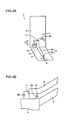
- a resonator 9 is placed in casing 2 in the fourth embodiment as one method for achieving the above-mentioned purpose.
- Resonator 9 is placed at a position close to dipole antenna 5 at the time when cover 3 is closed as illustrated in Fig. 5B, and excited by dipole antenna 5 in a non-contact state.
- dipole antenna 5 and its power supply means the same members as those used in the above-mentioned embodiments may be used.
- resonator 9 By installing resonator 9 at the above-mentioned position, it is possible to disperse frequencies having a low return loss, and consequently to obtain a frequency characteristic, for example, shown in Fig. 7B. In other words, it becomes possible to ensure two portions of bands having a return loss of approximately -6 dB, even when cover 3 is closed.
- a ⁇ /4 resonator with one end being short-circuited and the other end being opened [a resonator having a length L4 of ⁇ /4 + N x ⁇ /2 (N: an integer of not less than 1)] may be used, or a ⁇ /2 resonator with both of the ends being opened [a resonator having a length of N x ⁇ /2 (N: an integer of not less than 1)] may be used.
- resonator 9 for example, those having a plate shape, a line shape, a meandering shape and a helical shape may be used.
- matching circuits are switched by using a switch so that at the time when cover 3 is closed, frequencies having a low return loss can be dispersed.
- portable radio 1 in accordance with the fifth embodiment is provided with first and second matching circuits 12, 13, first and second switches 14, 15 and power supply 6.
- First matching circuit 12 is connected to dipole antenna 5 when cover 3 is opened.
- Second matching circuit 13 is connected to dipole antenna 5 when cover 3 is closed.
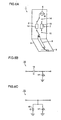
- Figs. 6B and 6C show structural examples of first and second matching circuits 12, 13. As illustrated in Figs. 6B and 6C, each of first and second matching circuits 12, 13 is provided with a capacitor 16 and a coil 17.
- first switch 14 switches and connects first and second matching circuits 12, 13 and power supply 6 as described above.
- second switch 15 switches and connects first and second matching circuits 12, 13 and dipole antenna 5.
- first matching circuit 12 is connected to power supply 6 and dipole antenna 5
- second matching circuit 13 is connected to power supply 6 and dipole antenna 5.
- the present invention can be effectively applied to a portable radio in which an antenna is installed in a cover (flip) that is attached to a casing so as to be freely opened and closed.
Landscapes
- Engineering & Computer Science (AREA)
- Computer Networks & Wireless Communication (AREA)
- Signal Processing (AREA)
- Details Of Aerials (AREA)
- Support Of Aerials (AREA)
- Mobile Radio Communication Systems (AREA)
- Variable-Direction Aerials And Aerial Arrays (AREA)
Abstract
Description
Claims (17)
- A portable radio comprising:a casing (2);a cover (3) attached to said casing (2) so as to be freely opened and closed;a dipole antenna (5) attached to said cover (3);power supply means (4a, 4b, 6a, 6b) for supplying power to said dipole antenna (5);open-close detection means (7) for detecting the opening/closing of said cover (3); andpower supply control means (8) for controlling said power supply means (4a, 4b, 6a, 6b) based upon results of detection of said open-close detection means (7).
- The portable radio according to claim 1, wherein said power supply means (4a, 4b, 6a, 6b) comprises parallel two-line type power supply lines (4a, 4b), said parallel two-line type power supply lines being excited in reversed phases in a state where said cover (3) is open, said parallel two-line type power supply lines being excited in the same phase in a state where said cover (3) is closed.
- The portable radio according to claim 1, wherein: said power supply means (4a, 4b, 6a, 6b) comprises a coaxial line (9), said coaxial line (9) being provided with an external conductor (9a) and an inner conductor (9b), with said external conductor (9a) and said casing (2) being short-circuited, and excites said inner conductor (9b) in a state where said cover (3) is open, and excites said external conductor (9a) in a state where said cover (3) is closed.
- The portable radio according to claim 3, wherein a power supply point (10) of said external conductor (9a) and a short-circuit point (11) of said external conductor (9a) to said casing (2) has a gap of a quarter wavelength.
- The portable radio according to claim 1, wherein said dipole antenna (5) is extended in a direction orthogonal to a length direction of said casing (2).
- The portable radio according to claim 1, wherein said dipole antenna (5) has a top end that is bent.
- The portable radio according to claim 1, wherein said dipole antenna (5) has a top end that is bent into a meandering shape.
- A portable radio comprising:wherein said resonator (9) is placed in a position close to said dipole antenna (5) when said cover (3) is closed.a casing (2);a cover (3) attached to said casing (2) so as to be freely opened and closed;a dipole antenna (5) attached to said cover (3);power supply means (6) for supplying power to said dipole antenna (5); anda resonator (9) installed in said casing (2),
- The portable radio according to claim 8, wherein said resonator (9) comprises a quarter wavelength resonator with one end being short-circuited, the other end being opened.
- The portable radio according to claim 8, wherein said resonator (9) comprises a half wavelength resonator with both of the ends being opened.
- The portable radio according to claim 8, wherein said dipole antenna (5) is extended in a direction orthogonal to a length direction of said casing (2).
- The portable radio according to claim 8, wherein said dipole antenna (5) has a top end that is bent.
- The portable radio according to claim 8, wherein said dipole antenna (5) has a top end that is bent into a meandering shape.
- A portable radio comprising:a casing (2);a cover (3) attached to said casing (2) so as to be freely opened and closed;a dipole antenna (5) attached to said cover (3);power supply means (6) for supplying power to said dipole antenna (5);open-close detection means (7) for detecting the opening/closing of said cover (3);first and second matching circuits (12, 13);a first switch (14) which, based upon the result of detection by said open-close detection means (7), makes a switchover between said first and second matching circuits (12, 13) and said power supply means (6); anda second switch (15) which, based upon the result of detection by said open-close detection means (7), makes a switchover between said first and second matching circuits (12, 13) and said dipole antenna (5).
- The portable radio according to claim 14, wherein said dipole antenna (5) is extended in a direction orthogonal to a length direction of said casing (2).
- The portable radio according to claim 14, wherein said dipole antenna (5) has a top end that is bent.
- The portable radio according to claim 14, wherein said dipole antenna (5) has a top end that is bent into a meandering shape.
Applications Claiming Priority (1)
| Application Number | Priority Date | Filing Date | Title |
|---|---|---|---|
| PCT/JP2000/003818 WO2001097325A1 (en) | 2000-06-12 | 2000-06-12 | Portable radio unit |
Publications (2)
| Publication Number | Publication Date |
|---|---|
| EP1296407A1 true EP1296407A1 (en) | 2003-03-26 |
| EP1296407A4 EP1296407A4 (en) | 2005-03-09 |
Family
ID=11736145
Family Applications (1)
| Application Number | Title | Priority Date | Filing Date |
|---|---|---|---|
| EP00935652A Withdrawn EP1296407A4 (en) | 2000-06-12 | 2000-06-12 | PORTABLE RADIO UNIT |
Country Status (4)
| Country | Link |
|---|---|
| EP (1) | EP1296407A4 (en) |
| JP (1) | JP3830892B2 (en) |
| CN (1) | CN1370341A (en) |
| WO (1) | WO2001097325A1 (en) |
Cited By (15)
| Publication number | Priority date | Publication date | Assignee | Title |
|---|---|---|---|---|
| WO2005112188A1 (en) * | 2004-04-30 | 2005-11-24 | Sony Ericsson Mobile Communications Ab | Selectively engaged antenna matching for a mobile terminal |
| EP1603189A1 (en) * | 2004-05-31 | 2005-12-07 | Kabushiki Kaisha Toshiba | Broadcast receiver |
| WO2006111129A1 (en) * | 2005-04-21 | 2006-10-26 | Eads Deutschland Gmbh | Collapsible monopolar antenna |
| FR2889393A1 (en) * | 2005-08-01 | 2007-02-02 | Sagem Comm | Clam type cellular telephone, has speakers, and dipole antenna with wire strands extending, in parallel, partially along external edges of respective shells of case, where edges are at maximum distance from each other when case is closed |
| WO2007128340A1 (en) * | 2006-05-04 | 2007-11-15 | Fractus, S.A. | Wireless portable device including internal broadcast receiver |
| EP1939979A1 (en) * | 2006-12-29 | 2008-07-02 | Broadcom Corporation | An integrated circuit antenna structure |
| FR2917254A1 (en) * | 2007-06-05 | 2008-12-12 | Heol Design Soc Par Actions Si | Communication device i.e. radiolocation device, for geolocation of e.g. train, has power supply conversion circuit and controllable switch s controlled for selecting voltage at power supply of radio communication antenna |
| US7557761B2 (en) | 2007-01-19 | 2009-07-07 | Panasonic Corporation | Array antenna apparatus having at least two feeding elements and operable in multiple frequency bands |
| US7589687B2 (en) | 2006-12-05 | 2009-09-15 | Panasonic Corporation | Antenna apparatus provided with antenna element excited through multiple feeding points |
| US8742999B2 (en) | 2010-01-19 | 2014-06-03 | Panasonic Corporation | Antenna apparatus for simultaneously transmitting multiple radio signals with different radiation characteristics |
| US8754820B2 (en) | 2006-12-05 | 2014-06-17 | Panasonic Corporation | Antenna apparatus provided with electromagnetic coupling adjuster and antenna element excited through multiple feeding points |
| US9065286B2 (en) | 2005-07-12 | 2015-06-23 | Massachusetts Institute Of Technology | Wireless non-radiative energy transfer |
| US9172138B2 (en) | 2012-08-27 | 2015-10-27 | Huawei Device Co., Ltd. | Dual-feedpoint antenna system and method for feedpoint switchover of dual-feedpoint antenna system |
| US9831682B2 (en) | 2008-10-01 | 2017-11-28 | Massachusetts Institute Of Technology | Efficient near-field wireless energy transfer using adiabatic system variations |
| US10097044B2 (en) | 2005-07-12 | 2018-10-09 | Massachusetts Institute Of Technology | Wireless energy transfer |
Families Citing this family (5)
| Publication number | Priority date | Publication date | Assignee | Title |
|---|---|---|---|---|
| JP3886932B2 (en) * | 2003-06-04 | 2007-02-28 | 太陽誘電株式会社 | Antenna mounting substrate and PC card provided with the same |
| KR101356409B1 (en) * | 2007-03-27 | 2014-01-27 | 메사추세츠 인스티튜트 오브 테크놀로지 | Wireless energy transfer |
| JP5318885B2 (en) * | 2008-11-26 | 2013-10-16 | 京セラ株式会社 | Mobile device |
| CN201975511U (en) * | 2010-12-15 | 2011-09-14 | 中兴通讯股份有限公司 | Terminal antenna |
| CN109193123B (en) * | 2018-08-29 | 2021-02-09 | Oppo广东移动通信有限公司 | Electronic device, antenna radiator control method, and storage medium |
Family Cites Families (5)
| Publication number | Priority date | Publication date | Assignee | Title |
|---|---|---|---|---|
| JP2794987B2 (en) * | 1991-05-31 | 1998-09-10 | 日本電気株式会社 | Portable wireless devices |
| US5969688A (en) * | 1994-04-26 | 1999-10-19 | Ireland; Frank E. | Cellular phone antenna with reactance cancellation |
| US5561436A (en) * | 1994-07-21 | 1996-10-01 | Motorola, Inc. | Method and apparatus for multi-position antenna |
| TW295733B (en) * | 1994-09-15 | 1997-01-11 | Motorola Inc | |
| US5542106A (en) * | 1994-09-15 | 1996-07-30 | Motorola, Inc. | Electronic device having an RF circuit integrated into a movable housing element |
-
2000
- 2000-06-12 WO PCT/JP2000/003818 patent/WO2001097325A1/en not_active Ceased
- 2000-06-12 JP JP2002511423A patent/JP3830892B2/en not_active Expired - Fee Related
- 2000-06-12 EP EP00935652A patent/EP1296407A4/en not_active Withdrawn
- 2000-06-12 CN CN00811709A patent/CN1370341A/en active Pending
Cited By (23)
| Publication number | Priority date | Publication date | Assignee | Title |
|---|---|---|---|---|
| WO2005112188A1 (en) * | 2004-04-30 | 2005-11-24 | Sony Ericsson Mobile Communications Ab | Selectively engaged antenna matching for a mobile terminal |
| US6995716B2 (en) | 2004-04-30 | 2006-02-07 | Sony Ericsson Mobile Communications Ab | Selectively engaged antenna matching for a mobile terminal |
| EP1603189A1 (en) * | 2004-05-31 | 2005-12-07 | Kabushiki Kaisha Toshiba | Broadcast receiver |
| WO2006111129A1 (en) * | 2005-04-21 | 2006-10-26 | Eads Deutschland Gmbh | Collapsible monopolar antenna |
| US10666091B2 (en) | 2005-07-12 | 2020-05-26 | Massachusetts Institute Of Technology | Wireless non-radiative energy transfer |
| US11685270B2 (en) | 2005-07-12 | 2023-06-27 | Mit | Wireless energy transfer |
| US11685271B2 (en) | 2005-07-12 | 2023-06-27 | Massachusetts Institute Of Technology | Wireless non-radiative energy transfer |
| US9831722B2 (en) | 2005-07-12 | 2017-11-28 | Massachusetts Institute Of Technology | Wireless non-radiative energy transfer |
| US10141790B2 (en) | 2005-07-12 | 2018-11-27 | Massachusetts Institute Of Technology | Wireless non-radiative energy transfer |
| US10097044B2 (en) | 2005-07-12 | 2018-10-09 | Massachusetts Institute Of Technology | Wireless energy transfer |
| US9065286B2 (en) | 2005-07-12 | 2015-06-23 | Massachusetts Institute Of Technology | Wireless non-radiative energy transfer |
| EP1750420A1 (en) * | 2005-08-01 | 2007-02-07 | Sagem Communication S.A. | Electronic apparatus provided with broadcasting or radio communication means |
| FR2889393A1 (en) * | 2005-08-01 | 2007-02-02 | Sagem Comm | Clam type cellular telephone, has speakers, and dipole antenna with wire strands extending, in parallel, partially along external edges of respective shells of case, where edges are at maximum distance from each other when case is closed |
| US8472908B2 (en) | 2006-04-03 | 2013-06-25 | Fractus, S.A. | Wireless portable device including internal broadcast receiver |
| WO2007128340A1 (en) * | 2006-05-04 | 2007-11-15 | Fractus, S.A. | Wireless portable device including internal broadcast receiver |
| US7589687B2 (en) | 2006-12-05 | 2009-09-15 | Panasonic Corporation | Antenna apparatus provided with antenna element excited through multiple feeding points |
| US8754820B2 (en) | 2006-12-05 | 2014-06-17 | Panasonic Corporation | Antenna apparatus provided with electromagnetic coupling adjuster and antenna element excited through multiple feeding points |
| EP1939979A1 (en) * | 2006-12-29 | 2008-07-02 | Broadcom Corporation | An integrated circuit antenna structure |
| US7557761B2 (en) | 2007-01-19 | 2009-07-07 | Panasonic Corporation | Array antenna apparatus having at least two feeding elements and operable in multiple frequency bands |
| FR2917254A1 (en) * | 2007-06-05 | 2008-12-12 | Heol Design Soc Par Actions Si | Communication device i.e. radiolocation device, for geolocation of e.g. train, has power supply conversion circuit and controllable switch s controlled for selecting voltage at power supply of radio communication antenna |
| US9831682B2 (en) | 2008-10-01 | 2017-11-28 | Massachusetts Institute Of Technology | Efficient near-field wireless energy transfer using adiabatic system variations |
| US8742999B2 (en) | 2010-01-19 | 2014-06-03 | Panasonic Corporation | Antenna apparatus for simultaneously transmitting multiple radio signals with different radiation characteristics |
| US9172138B2 (en) | 2012-08-27 | 2015-10-27 | Huawei Device Co., Ltd. | Dual-feedpoint antenna system and method for feedpoint switchover of dual-feedpoint antenna system |
Also Published As
| Publication number | Publication date |
|---|---|
| WO2001097325A1 (en) | 2001-12-20 |
| EP1296407A4 (en) | 2005-03-09 |
| CN1370341A (en) | 2002-09-18 |
| JP3830892B2 (en) | 2006-10-11 |
Similar Documents
| Publication | Publication Date | Title |
|---|---|---|
| EP1296407A1 (en) | Portable radio unit | |
| KR101025680B1 (en) | Antenna device and mobile wireless communication terminal | |
| KR100192189B1 (en) | Electronic device with integrated RF circuit in a retractable housing element | |
| US5557293A (en) | Multi-loop antenna | |
| KR100993439B1 (en) | Antenna device and radio communication device | |
| JP4015024B2 (en) | Antenna device | |
| US7164387B2 (en) | Compact tunable antenna | |
| US6400931B1 (en) | Card-like wireless communication device | |
| JP3243825B2 (en) | Portable electronic devices | |
| US6653977B1 (en) | Wireless handset | |
| JP3438016B2 (en) | Multi-frequency resonant inverted-F antenna | |
| US6573867B1 (en) | Small embedded multi frequency antenna for portable wireless communications | |
| KR20030032001A (en) | Apparatus and method for enhancing low-frequency operation of mobile communication antennas | |
| US6052088A (en) | Multi-band antenna | |
| JPWO2001097325A1 (en) | Portable radio | |
| US5943021A (en) | Swivel antenna with parasitic tuning | |
| JP2008294635A (en) | Antenna device and portable radio | |
| US7928914B2 (en) | Multi-frequency conductive-strip antenna system | |
| JP4440243B2 (en) | Mobile device | |
| US20100225544A1 (en) | Slot antenna and portable wireless terminal | |
| EP1280226A1 (en) | Portable radio device | |
| EP1962372B1 (en) | Miniature broadband antenna with inductive chassis coupling | |
| JP4049185B2 (en) | Portable radio | |
| CN101507046A (en) | Multi-part wireless device | |
| JP2003133828A (en) | Antenna apparatus for radio communication terminal |
Legal Events
| Date | Code | Title | Description |
|---|---|---|---|
| PUAI | Public reference made under article 153(3) epc to a published international application that has entered the european phase |
Free format text: ORIGINAL CODE: 0009012 |
|
| 17P | Request for examination filed |
Effective date: 20020312 |
|
| AK | Designated contracting states |
Kind code of ref document: A1 Designated state(s): AT BE CH CY DE DK ES FI FR GB GR IE IT LI LU MC NL PT SE Designated state(s): AT BE CH CY DE DK ES FI FR GB GR IE IT LI LU MC NL PT SE |
|
| AX | Request for extension of the european patent |
Extension state: AL LT LV MK RO SI |
|
| RBV | Designated contracting states (corrected) |
Designated state(s): DE FR GB |
|
| RIC1 | Information provided on ipc code assigned before grant |
Ipc: 7H 01Q 5/00 B Ipc: 7H 01Q 9/42 B Ipc: 7H 01Q 9/26 B Ipc: 7H 01Q 9/28 B Ipc: 7H 01Q 1/08 B Ipc: 7H 01Q 9/30 B Ipc: 7H 04B 7/26 B Ipc: 7H 04B 1/38 B Ipc: 7H 01Q 1/24 A |
|
| A4 | Supplementary search report drawn up and despatched |
Effective date: 20050120 |
|
| STAA | Information on the status of an ep patent application or granted ep patent |
Free format text: STATUS: THE APPLICATION HAS BEEN WITHDRAWN |
|
| 18W | Application withdrawn |
Effective date: 20050324 |