EP1296323A2 - Holding mechanism of an optical disk clamper and an optical disk drive using the same - Google Patents
Holding mechanism of an optical disk clamper and an optical disk drive using the same Download PDFInfo
- Publication number
- EP1296323A2 EP1296323A2 EP02256434A EP02256434A EP1296323A2 EP 1296323 A2 EP1296323 A2 EP 1296323A2 EP 02256434 A EP02256434 A EP 02256434A EP 02256434 A EP02256434 A EP 02256434A EP 1296323 A2 EP1296323 A2 EP 1296323A2
- Authority
- EP
- European Patent Office
- Prior art keywords
- optical disk
- unit
- disk clamper
- heat radiation
- clamper
- Prior art date
- Legal status (The legal status is an assumption and is not a legal conclusion. Google has not performed a legal analysis and makes no representation as to the accuracy of the status listed.)
- Granted
Links
- 230000003287 optical effect Effects 0.000 title claims abstract description 206
- 230000007246 mechanism Effects 0.000 title claims abstract description 41
- 230000005855 radiation Effects 0.000 description 106
- 239000004065 semiconductor Substances 0.000 description 35
- 238000010586 diagram Methods 0.000 description 9
- 229910000831 Steel Inorganic materials 0.000 description 4
- 239000010959 steel Substances 0.000 description 4
- 238000004519 manufacturing process Methods 0.000 description 3
- 229920003002 synthetic resin Polymers 0.000 description 3
- 239000000057 synthetic resin Substances 0.000 description 3
- 238000013459 approach Methods 0.000 description 2
- 239000000428 dust Substances 0.000 description 2
- 238000007689 inspection Methods 0.000 description 2
- 239000002184 metal Substances 0.000 description 2
- 238000003825 pressing Methods 0.000 description 2
- 238000005476 soldering Methods 0.000 description 2
- 238000005452 bending Methods 0.000 description 1
- 238000000034 method Methods 0.000 description 1
- 238000012986 modification Methods 0.000 description 1
- 230000004048 modification Effects 0.000 description 1
- 230000008569 process Effects 0.000 description 1
- 229910052710 silicon Inorganic materials 0.000 description 1
- 239000010703 silicon Substances 0.000 description 1
- 229920002050 silicone resin Polymers 0.000 description 1
- 229910000679 solder Inorganic materials 0.000 description 1
Images







Classifications
-
- G—PHYSICS
- G11—INFORMATION STORAGE
- G11B—INFORMATION STORAGE BASED ON RELATIVE MOVEMENT BETWEEN RECORD CARRIER AND TRANSDUCER
- G11B17/00—Guiding record carriers not specifically of filamentary or web form, or of supports therefor
- G11B17/02—Details
- G11B17/022—Positioning or locking of single discs
- G11B17/028—Positioning or locking of single discs of discs rotating during transducing operation
- G11B17/0284—Positioning or locking of single discs of discs rotating during transducing operation by clampers
- G11B17/0285—Positioning or locking of single discs of discs rotating during transducing operation by clampers mounted on a bridge
-
- G—PHYSICS
- G11—INFORMATION STORAGE
- G11B—INFORMATION STORAGE BASED ON RELATIVE MOVEMENT BETWEEN RECORD CARRIER AND TRANSDUCER
- G11B33/00—Constructional parts, details or accessories not provided for in the other groups of this subclass
- G11B33/14—Reducing influence of physical parameters, e.g. temperature change, moisture, dust
Definitions
- the present invention generally relates to an optical disk clamper, and more particularly, to the retracting mechanism of an optical disk clamper and an optical disk drive using the same.
- a type of optical disk drive has an optical disk clamper held in a holding unit.
- a turntable moves upward and the optical disk clamper fits in and is magnetically attracted by the turntable so that the optical disk is clamped on the turntable.
- the optical disk clamper holding unit has an opening portion through which the optical disk clamper is built in, but supports the optical disk clamper so that the optical disk clamper does not come out once built in.
- FIGs. 1A - 1C are schematic diagrams showing a conventional optical disk clamper holding unit 10.
- This optical disk clamper holding unit 10 has a surrounding unit 11, a flange unit 12, and a built-in opening unit 13.
- the surrounding unit 11 is shaped like a ring of which a portion is removed. The removed portion corresponds to the built-in opening unit 13. Though the built-in opening unit 13 is formed as small as possible, no devisal is employed.
- the flange unit 12 protrudes inwardly from the surrounding unit 11.
- the optical disk clamper is shaped like a reel, and has a hub unit 21, an upper flange unit 22, and a lower flange unit 23.
- the optical disk clamper 20 is built in the optical disk clamper holding unit 10 through the built-in opening unit 13 by bending the lower flange unit 23.
- the hub unit 21 is positioned inside of the flange unit 12 and the upper flange unit 22 is supported by the flange unit 12 in the manner that the optical disk clamper is freely movable in the optical disk clamper holding unit 10, but does not come off through the built-in opening unit 13.
- Oc is the center of the optical disk clamper 20
- Oh is the center of the optical disk clamper holding unit 10.
- the optical disk clamper 10 fits in the turn table and is magnetically attracted by the turn table, the optical disk is clamped on the turn table.
- the range of clearance in which the optical disk clamper 20 is movable in the holding unit 10 will be considered as below.
- the optical disk clamper 20 can move in the direction of X1, X2, and Y1 until the hub unit 21 touches the flange unit 12. As showed in Fig. 1B, the optical disk clamper 20 can move the distance ⁇ X1 in the X1 direction. In the direction toward the opening unit 13, that is, the Y2 direction, however, the optical disk clamper 20 can move, as showed in Fig. 1C, until the upper flange unit 22 touches the edges 11a and 11b of the surrounding unit 11, that is, the distance ⁇ Y2.
- the distance ⁇ Y2 is about twice the distance ⁇ Y1. If the optical disk clamper 20 is moved in the holding unit 10 in the Y2 direction, there is a risk that, when the turntable moves upward with the optical disk, the optical disk clamper 10 does not fit in the turn table and the optical disk is not normally clamped.
- Fig. 2 is a schematic diagram showing a conventional heat radiation mechanism of an electronic component.
- the heat radiation mechanism showed in Fig. 2 is employed by disk drives such as CD-R.
- the heat generated by a semiconductor component 220 is radiated by a bottom cover 250 that carries out the function of a heat radiation plate.
- the leads 230 of the semiconductor component 220 are connected and fixed to a circuit board 210 with soldering 240.
- the semiconductor component 220 generates heat when it is operated.
- the bottom cover 250 is attached to the disk drive so that the bottom cover 250 faces the circuit board 210.
- This bottom cover 250 is made of highly conductive metal plate and functions as a heat radiation plate.
- a heat radiation unit 260 is formed at the position opposed to the semiconductor component 220 on the bottom cover 250 so that the distance between the bottom cover 250 and the semiconductor component 220 becomes small.
- a heat radiation sheet 270 is provided on the semiconductor component 220 to thermally connect the semiconductor component 220 and the bottom cover 250 so that this heat radiation sheet 270 touches the bottom cover 250 (heat radiation unit 260) when the bottom cover 250 is attached to the optical disk drive.
- the heat generated by the semiconductor component 220 is transferred to the bottom cover 250 through the heat radiation sheet 270 and radiated by the bottom cover 250.
- the performance of the heat radiation mechanism is affected by assembly error of the apparatus, manufacturing error of components, and tolerances (hereinafter, these are referred to as "assembly errors" as a whole).
- the heat radiation sheet 270 may not touch the bottom cover 250 (heat radiation unit 260) as showed in Fig. 3. If the heat radiation sheet 270 does not touch the bottom cover 250, the heat generated by the semiconductor component 220 is not efficiently transferred to the bottom cover 250.
- an optical disk clamper holding mechanism that holds an optical disk clamper having a hub, an upper flange unit, and a lower flange unit, according to an embodiment of the present invention, includes a surrounding unit that holds said upper flange unit, a flange unit that supports said upper flange unit and holds said hub unit, said flange unit being shaped like a semicircle, projecting inwardly from said surrounding unit and having a flange opening unit between edges in the circumferential direction, a rib that stops, when said optical disk clamper moves in the direction of said flange opening unit, a rim portion of said upper flange unit of said optical disk clamper, said rib protruding inwardly at a position opposite to said flange opening unit.
- the optical disk clamper holding mechanism improves the reliability of clamping.
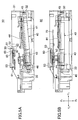
- FIG. 4 is a top view showing an optical disk drive 30.
- a disk tray and an optical base unit assembly are not shown in Fig. 4.
- Figs. 5A and 5B are side views showing the optical disk drive 30.
- the disk tray is not shown.
- the arrow X1-X2 indicates the width direction of the optical disk drive 30;
- the arrow Y1-Y2 indicates the depth direction of the optical disk drive 30;
- the arrow Z1-Z2 indicates the height direction of the optical disk drive 30.
- the optical disk drive 30 includes a housing 31 that is a box made of synthetic resin, a disk tray (not showed), and an optical base unit assembly 40.
- the optical disk drive 30 is horizontally built into the system unit of a computer and so forth.
- the optical base unit assembly 40 is provided with a square supporting base 41, a turn table 42, a motor 43 that rotates the turn table 42, an optical head 44 that reads information recorded in an optical disk 70, and a motor (not showed) that actuates the optical head 44.
- the supporting base 41 has an axis 45 that is located on the Y1 side of the supporting base 41 and protrudes in the X1-X2 direction.
- the axis 45 is supported by a bearing 32 of the housing 31.
- the supporting base 41 further has a rod 46 that is located on the Y2 side of the supporting base 41.
- the rod 46 is supported by a cam ditch formed on a cam member 33 fixed on the housing 31. Accordingly, the optical base unit assembly 40 is supported in the housing 31. As showed in Fig.
- the optical base unit assembly 40 tilts with the Y2 side of the optical base unit assembly 40 moved downward.
- the turntable 42 is positioned at a lower level.
- the optical disk 70 is, for example, a CD, a CD-ROM, a CD-R, a CD-RW, and a DVD.
- the turntable 42 is provided with a cone trapezoid shaped convex unit 42a at the center of the turntable 42, a hole unit 42b at the center of the convex unit 42a, and a ring-shaped permanent magnet 42c fixed on the top face of the convex unit 42a.
- Fig. 6B shows the structure of the turntable 42 in detail.
- the housing 31 has a bridge unit 34 crossing in the X1-X2 directions at the top face side, and an optical disk clamper holding unit 50 at the center of the bridge unit 34.
- An optical disk clamper 60 (showed in Fig. 6A) is built into this optical disk clamper holding unit 50 with some clearance as showed in Figs. 4 and 5A.
- the optical disk clamper 60 is a reel shaped component made of synthetic resin that has a hub unit 61, upper flange unit 63, and a lower flange unit 62.
- the optical disk clamper 60 is provided with a concave unit 64 at the center of the bottom face and a convex unit 65 protruding downward at the center of the concave unit 64.
- the convex unit 65 a ring shaped steel member, is built into the concave unit 64.
- the cam member 33 moves in the X2 direction, the cam ditch pushes up the rod 46, and the optical base unit assembly is set at a horizontal position as showed in Fig. 5B.
- the optical disk 70 of which the rim around the center hole is supported by the turntable 42 floats over the disk tray, and the optical disk clamper 60 is slightly pushed up.
- the convex unit 42a fits in the concave unit 64, and the hole unit 42b also fits around (receives) the convex unit 65. Since the steel convex unit 65 is attracted by the permanent magnet 42c, the optical disk 70 is clamped on the turntable 36.
- a motor 43 is activated to rotate the optical disk 70 and the information recorded in the optical disk 70 is read by the optical head 44. While being rotated, the optical disk clamper 60 remains at a position in which it does not touch the optical disk clamper holding unit 50.
- the optical disk drive 10 When the optical disk drive 10 is instructed to stop, it reverses the operation of loading.
- the optical base unit assembly 30 tilts as showed in Fig. 5A, and the disk tray is subsequently moved in the Y2 direction.
- the optical disk is released from the clamp and discharged out of the housing 31.
- the optical disk clamper holding unit 50 will be described next.
- the optical disk clamper holding unit 50 is a shaped component made of synthetic resin. It has a surrounding unit 51, a flange unit 52, a connection unit 53, ribs 54, 55, a built-in opening unit 56, and opening units 57, 58.
- the surrounding unit 51 is shaped like a ring, of which a portion of 1/4 is removed. The removed portion is the opening unit 57.
- the surrounding unit 51 holds the upper flange unit 63 of the optical disk clamper 60.
- the flange unit 52 inwardly protrudes from the Z2 side of the surrounding unit 51 and is substantially shaped like a semicircle.
- the opening 58 is provided between the two end edges of the flange 52 in the circumferential direction.
- the built-in opening unit 56 is formed between the flange opening unit 58 and the surrounding opening unit 57.
- the inner diameter D1 of the surrounding unit 51 is greater than the diameter D11 of the upper flange unit 63 of the optical disk clamper 60.
- the inner diameter D2 of the flange unit 52 is greater than the diameter D12 of the hub unit 61 of the optical disk clamper 60.
- the opening unit 57 is in the X-Z plane, and the built-in opening unit 56 is in the X-Y plane.
- W1 indicates the width of the opening unit 57 in the X1-X2 directions, and at the same time, is the width of the Y2 edge of the built-in opening unit 56.
- W1 is shorter than the diameter D11 of the upper flange unit 63 of the optical disk clamper 60.
- the width W1 is the shortest length wherein the optical disk clamper 60 can be built into the optical disk clamper holding unit 50.
- W2 indicates the width of the flange opening unit 58 in the X1-X2 directions, and is equal to the diameter D12 of the hub unit 61 of the optical disk clamper 60.
- connection unit 53 stretches in the X1-X2 directions and connects both edges of the surrounding unit 51 at the upper side.
- the connection unit 53 reinforces the portion of the surrounding unit 51 that protrudes from the bridge unit 34 in the Y2 direction.
- the ribs 54, 55 protrude from the respective edges 51a, 51b of the surrounding unit 51 in the radial direction toward the center Oh of the optical disk clamper holding unit 50.
- the width of the ribs 54 and 55 is W10.
- the ribs 54 and 55 reduce the clearance of the optical disk clamper 60 in the Y2 direction in the disk clamper holding unit 50 without making it difficult to build the optical disk clamper 60 into the optical disk clamper holding unit 50.
- the ribs 54 and 55 are formed in the portion of the surrounding unit 51 that is opposite to the flange opening unit 58.
- the hub unit 61 is positioned in the flange unit 52 and the upper flange unit 63 is supported by the flange unit 52.
- a portion of the upper flange unit 63 protrudes from the optical disk clamper holding unit 50 in the Y2 direction.
- the optical disk clamper 60 is movable in the optical disk clamper holding unit 50, but it is supported so that it does not come off through the flange opening unit 58.
- Oc indicates the center of the optical disk clamper, and Oh indicates the center of the optical disk clamper holding unit 50.
- the movement of the optical disk clamper 60 in the direction of Y1, X1, and X2 is restricted because the hub unit 61 touches the inner edge 52a of the flange 52.
- the ranges in which the optical disk clamper 60 can move freely are ⁇ Y1a, ⁇ X1a, and ⁇ X2a, respectively, all of which are small.
- the movement of the optical disk clamper 60 is restricted because the rim portion of the upper flange unit 63 of the optical disk clamper 60 on the Y2 side touches the ribs 54 and 55.
- the range in which the optical disk clamper 60 can move in the Y2 direction is ⁇ Y2a.
- the optical disk clamper 60 moves until the rim portion of the upper flange unit 63 of the optical disk clamper 60 on the Y2 side touches the edge portions 51a and 51b of the surrounding unit 51 in the circumferential direction.
- the movable range becomes ⁇ Y2b.
- the above range ⁇ Y2a is about a half of the range ⁇ Y2b, and is at the same size range as the above ranges ⁇ Y1a, ⁇ X1a, and ⁇ X2a.
- the movable range in which the optical disk clamper 60 can move in the holding unit 50 becomes equally short in all the directions. Whichever direction the optical disk clamper 60 is moved, an optical disk 70 is clamped normally, when the turntable moves upward with the optical disk 70 as showed in Figs. 5A and 5B, since the convex unit 42a surely fits in the concave unit 64 and the hole unit 42b surely fits around and receives the convex unit 65.
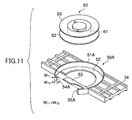
- FIGs. 11A and 11B show another embodiment of the present invention.
- elements corresponding to those showed in Figs. 7A and 7B are referred to by the same numerals.
- An optical disk clamper holding unit 50A has ribs 54A and 55A.
- the ribs 54A and 55A are each shaped like a triangle of which the width W11 at the Z1 side is shorter than the width W10.
- the distance between the rim portion of the upper flange unit 63 of the optical disk clamper 60 and the ribs 54A and 55A becomes greater compared to the distance before the optical disk clamper 60 is pushed upward. Accordingly, when the optical disk clamper 60 is rotated in the optical disk clamper holding unit 50A, the risk that the optical disk clamper 60 touches the ribs 54A and 55A is eliminated.
- Figs. 12A and 12B show an optical disk clamper holding unit 50B according to yet another embodiment of the present invention.
- elements corresponding to those showed in Figs. 7A and 7B are referred to by the same numerals.
- the surrounding unit 51B is shaped like a ring, but no portion of the ring is removed.
- the surrounding unit 51B does not have an opening unit corresponding to the opening unit 57 showed in Fig. 7B.
- Ribs 54B and 55B are formed at positions on the inner face of the surrounding unit 51B opposite to the flange opening unit 58.
- a rib is provided on the surrounding unit at a position opposing the flange opening unit, the rib protruding toward the inside of the surrounding unit.
- the width at the upper side of the rib described above may be shorter than the width at the lower side of the rib. Accordingly, in the case the optical disk is clamped and, as a result, the optical disk clamper is slightly pushed up, the gap between the rim portion of the upper flange unit of the optical disk clamper and the rib becomes greater, compared to the gap before the optical disk clamper is pushed up. Consequently, the risk of the optical disk clamper touching the rib while the optical disk clamper is rotating is eliminated.
- an optical disk drive can have the optical disk clamper holding unit described above, a turn table that clamps the optical disk with the optical disk clamper, and an optical head that reads information recorded in the optical disk rotated by the turn table. Accordingly, it is possible to improve the reliability of clamping for the optical disk drive.
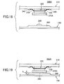
- FIGs. 18 and 19 show a heat radiation mechanism 300A for an electronic component according to an embodiment of the present invention.
- This heat radiation mechanism 300A can be built in a disk drive 100 showed in Figs. 13 - 15, for example. A brief description on the disk drive 100 will be given before the heat radiation mechanism 300A.
- the disk drive 100 is, for example, a CD-R/CD-RW drive.
- the disk drive 100 mainly includes a base chassis 110, a tray 120, a traverse base 130, a bottom cover 140, and a circuit board 310.
- the base chassis 110 is shaped like a box, and each component constituting the disk drive 100, such as the tray 120, the traverse base 130, the bottom cover 140, is provided inside of the base chassis 110.
- a bridge unit 190 is provided over the base chassis 110 as showed in Fig. 13, and a clamper 200 is built in at the center of the bridge unit 190.
- the clamper 200 and a turntable (not showed) provided in the traverse base 130 together clamp the disk and rotate it at a predetermined rotative speed.
- the tray 120 can move in the directions indicated by an arrow X1 - X2.
- a disk supporting unit 150 is formed on the tray 120 to support the disk.
- the disk In the case where the tray 120 moves in the X1 direction relative to the base chassis 110 (eject state), the disk is set in or removed from the tray 120.
- the tray 120 moves in the X2 direction relative to the base chassis 110 (loading state)
- the disk is clamped between the clamper 200 and the turntable and rotated.
- the optical pickup 170 reads and/or writes information in the disk.
- the traverse base 130 moves up and down relative to the tray 120.
- the traverse base 130 is provided with the turntable and the optical pickup 170 as described above.
- the optical pickup 170 is supported by guiding shafts 180 at both sides, and moves in the radial direction (indicated by an arrow X1 - X2) of the disk loaded in the disk drive 100 to write and read information in the disk.
- the tray 120 is provided with an opening unit 160.
- the above turntable meets the clamper 200 through this opening unit 160, and the optical pickup 170 performs reading and writing operations through the opening unit 160.
- the turn table While the tray 120 is moving to eject or load the disk, the turn table stays at a lower position so that the turn table does not disturb the motion of the tray 120.
- the turntable and the traverse base 130 move upward together to clamp the disk by fitting in the clamper 200.
- the traverse base 130 is positioned so that the traverse base 130 covers the circuit board 310 provided at the bottom of the base chassis 110.
- the circuit board 310 is provided with various electronic components such as a semiconductor component 320. These electronic components write and read information in the disk, and actuate various actuators (such as actuating mechanisms of the tray 120).
- the circuit board 310 may gather dust or the electronic components such as the semiconductor component 320 may be damaged.
- the bottom cover 140 is provided so that the circuit board 310 does not gather dust and the electronic components are not damaged.
- the bottom cover 140 is made of metal plate such as steel plate having high thermal conductivity.
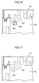
- Fig. 15 is bottom view of the disk drive 100 showing the bottom cover 140 provided at the bottom of the base chassis 110. As showed in the figure, a heat radiation mechanism 300A and a checking window 400 are formed on the bottom cover 140.
- the checking window 400 is described by reference to Fig. 16 in addition to Fig. 15.
- a ground harness 410 is connected to the circuit board 310. This ground harness 410 is connected to a connector 420 provided on the circuit board 310.
- the ground harness must be connected to the circuit board 310 so that the electronic circuit provided on the circuit board 310 is normally operated. An inspection is performed to assure that the ground harness 410 is surely connected to the circuit board 310.
- the bottom cover 140 is provided with a checking window 400 at a position where the connector 420 faces when the bottom cover 140 is assembled to the base chassis 110. As showed in Fig. 16, even if the bottom cover 140 is assembled to the base chassis 110, one can check through the checking window 400 whether the ground harness 410 is firmly connected to the connector 420. Accordingly, it becomes easy to check the connection of the ground harness 41 and the connector 42.
- the heat radiation mechanism 300A will be described next. As showed in Fig. 15, two heat radiation mechanisms 300A, which are identical, are provided in this embodiment.
- Figs. 18 and 19 are enlarged side views showing the heat radiation mechanism 300A.
- the heat radiation mechanism 300A according to an embodiment is structured to radiate the heat generated by the semiconductor component 320 provided on the circuit board 310. Though the heat radiation mechanism according to this embodiment radiates the heat generated by the semiconductor component 320 as an electronic component, the present invention is not limited to the heat radiation for the semiconductor component 320, but applicable to other heat-generating components.
- the semiconductor component 320 is fixed on the circuit board 310 by soldering the lead 330 to the circuit board 310 (solder 340). This semiconductor component 320 generates heat while it is activated so that the disk drive reads or writes information in the disk.
- a heat radiation sheet 370A is provided on the top face of the semiconductor component 320 (the semiconductor component 320 is upside down in Figs. 18 and 19). This heat radiation sheet 370A is mainly made of silicone resin having high thermal conductivity. The heat radiation sheet 370A has high thermal conductivity. Since the main component of heat radiation sheet 370A is silicon, the heat radiation sheet 370A is flexible.
- the bottom cover 140 opposing to the circuit board 310 is made of steel plate having high thermal conductivity. Additionally, the heat radiation unit 360 is formed on the bottom cover 140 at the position opposing to the semiconductor component 320. Accordingly, the bottom cover 140 is structured to approach the semiconductor component 320.
- the bottom cover 140 (heat radiation unit 360) according to this embodiment is provided with a boss unit 380 protruding toward the electronic component at the position in which heat radiation sheet 370A touches the bottom cover 140.
- the boss unit 380 is formed on the bottom cover 140 as a monolith.
- the boss unit 380 according to this embodiment is shaped like a hemisphere and the bottom cover 140 according to this embodiment is provided with only one boss unit 380 at the center of the heat radiation unit 360.
- the shape of the boss unit 380 is not limited to a hemisphere, but can be another shape that increases the contact area with the heat radiation sheet 370A.
- the number of the boss units 380 is not limited to one, but can be a plurality in order to increase the contact area with the heat radiation sheet 370A.
- the manufacturing of the disk drive 10 inevitably involves assembly error of the apparatus, manufacturing error of components, and tolerances (hereinafter, these are referred to as “assembly errors” as a whole). If the assembly errors are too great, the heat radiation sheet 370A and the bottom cover 140 (heat radiation unit 360) may separate (not be in contact).
- the heat radiation mechanism according to the embodiment includes the boss unit 380 protruding toward the semiconductor component 320, the boss unit 380 formed on the bottom cover 140 at the position at which the bottom cover 140 touches the heat radiation sheet 370A. Accordingly, the boss unit 380 surely touches the heat radiation sheet 370A even if the distance between the semiconductor component 320 and the heat radiation unit 360 (bottom cover 140) exceeds a predetermined value due to the above assembly errors. That is why the height of the boss unit 380 is set at a value greater than the maximum value of the above assembly errors and the like.
- the bottom cover 140 surely touches the heat radiation sheet 370A, and consequently, the heat generated by the semiconductor component 320 is surely radiated by the bottom cover 140 through the heat radiation sheet 370A.
- the boss unit 380 presses hard the heat radiation sheet 370A.
- the force is absorbed by the flexibility of the heat radiation sheet 370A.
- the structure having the boss unit 380 on the bottom cover 140 does not damage the bottom cover 140 and the semiconductor component 320. Additionally, because the bottom cover 140 (heat radiation unit 360) touches hard the heat radiation sheet 370A, the heat generated by the semiconductor component 320 is surely transferred to the bottom cover 140.
- Fig. 20 is an enlarged side view of a heat radiation mechanism 300B according to another embodiment of the present invention.
- the heat radiation mechanism 300B is characterized in that boss units 430A and 430B are formed on the heat radiation sheet 370B.
- the boss units 430A and 430B are formed one on each side of the heat radiation sheet 370B that is provided between the semiconductor component 320 and the bottom cover 140, even if the distance between the semiconductor component 320 and the heat radiation unit 360 (bottom cover 140) becomes more than a predetermined value due to the assembly errors and the like, the boss units 430A and 430B touch the semiconductor component 320 and the bottom cover 140 (heat radiation unit 360). That is why the height of the boss units 430A and 430B is set at a value greater than the maximum value of the above assembly errors and the like. Accordingly, even if the assembly errors and the like occur, the semiconductor component 320 and the bottom cover 140 surely touch each other through the heat radiation sheet 370B, and the heat generated by the semiconductor component 320 is surely radiated.
- the boss units 430A and 430B are pressed hard by the semiconductor component 420 and the bottom cover 140 (heat radiation unit 360).
- the heat radiation sheet 370B is also flexible, the force of the semiconductor component 320 and the heat radiation unit 360 pressing the boss units 430A and 430B is absorbed by the flexibility of the heat radiation sheet 370B, and the force does not cause the semiconductor component 320 and the bottom cover 140 to be damaged.
- the bottom cover 140 touches hard the heat radiation sheet 370B, the heat generated by the semiconductor component 320 is surely transferred to the bottom cover 140 for radiation.
- a heat radiation mechanism includes an electronic component mounted on a circuit board, a heat radiation plate, a heat radiation sheet provided between the electronic component and the heat radiation plate, and a boss unit formed on the heat radiation plate at a position where the heat radiation plate touches the heat radiation sheet, the boss unit protruding toward the electronic component, wherein heat generated by the electronic component is transferred to the heat radiation plate through the heat radiation sheet.
- a heat radiation mechanism includes an electronic component mounted on a circuit board, a heat radiation plate, a heat radiation sheet provided between the electronic component and the heat radiation plate, and one or more boss units formed on the heat radiation sheet at a position where the heat radiation sheet touches the electronic component and/or the heat radiation plate, wherein heat generated by the electronic component is transferred to the heat radiation plate through the heat radiation sheet.
- a heat radiation mechanism described above is characterized in that the heat radiation sheet is flexible.
- the force pressing the heat radiation sheet is absorbed by the flexibility of the heat radiation sheet, the force does not cause the electronic component and the heat radiation plate to be damaged.
Landscapes
- Holding Or Fastening Of Disk On Rotational Shaft (AREA)
Abstract
Description
Claims (4)
- An optical disk clamper holding mechanism that holds an optical disk clamper (60) having a hub unit (61), a lower flange unit (62), and an upper flange unit (63), characterized by:a surrounding unit (51, 51A, 51B) that holds said upper flange unit (63);a flange unit (52) that supports said upper flange unit (63) and holds said hub unit (61), said flange unit (52) being shaped like a semicircle, projecting inwardly from said surrounding unit (51, 51A, 51B) and having a flange opening unit (58) between edges in the circumferential direction;a rib (54, 55, 54A, 55A, 54B, 55B) that touches, when said optical disk clamper (60) moves in the direction of said flange opening unit (58), a rim portion of said upper flange unit (63) of said optical disk clamper (60), said rib (54, 55, 54A, 55A, 54B, 55B) protruding inwardly at a position opposite to said flange opening unit (58).
- The optical disk clamper holding mechanism as claimed in claim 1, characterized in that width at the upper side of said rib (54, 55, 54A, 55A, 54B, 55B) is smaller than width at the lower side of said rib (54, 55, 54A, 55A, 54B, 55B).
- An optical disk drive (30), characterized by:wherein said optical disk clamper holding mechanism further comprises:an optical disk clamper (60);a turn table (42) that clamps an optical disk (70) with said optical disk clamper (60);an optical head (44) that reads information recorded in said optical disk (70) while said optical disk (70) is rotated by said turntable (42); andan optical disk clamper holding mechanism that holds said optical disk clamper (60) having a hub unit (61), a lower flange unit (62), and an upper flange unit (63),a surrounding unit (51, 51A, 51B) that holds said upper flange unit (63);a flange unit (52) that supports said upper flange unit (63) and holds said hub unit (61), said flange unit (52) being shaped like a semicircle, projecting inwardly from said surrounding unit (51, 51A, 51B) and having a flange opening unit (58) between edges in the circumferential direction;a rib (54, 55, 54A, 55A, 54B, 55B) that touches, when said optical disk clamper (60) moves in the direction of said flange opening unit (58), a rim portion of said upper flange unit (63) of said optical disk clamper (60), said rib (54, 55, 54A, 55A, 54B, 55B) protruding inwardly at a position opposite to said flange opening unit (58).
- The optical disk drive as claimed in claim 3, characterized in that width at the upper side of said rib (54, 55, 54A, 55A, 54B, 55B) is smaller than width at the lower side of said rib (54, 55, 54A, 55A, 54B, 55B).
Applications Claiming Priority (4)
| Application Number | Priority Date | Filing Date | Title |
|---|---|---|---|
| JP2001285132A JP2003092481A (en) | 2001-09-19 | 2001-09-19 | Heat dissipation mechanism for electronic components |
| JP2001285132 | 2001-09-19 | ||
| JP2001344692A JP3716780B2 (en) | 2001-11-09 | 2001-11-09 | Optical disc clamper storage structure and optical disc apparatus provided with the same |
| JP2001344692 | 2001-11-09 |
Publications (3)
| Publication Number | Publication Date |
|---|---|
| EP1296323A2 true EP1296323A2 (en) | 2003-03-26 |
| EP1296323A3 EP1296323A3 (en) | 2004-01-21 |
| EP1296323B1 EP1296323B1 (en) | 2007-04-04 |
Family
ID=26622504
Family Applications (1)
| Application Number | Title | Priority Date | Filing Date |
|---|---|---|---|
| EP02256434A Expired - Lifetime EP1296323B1 (en) | 2001-09-19 | 2002-09-17 | Holding mechanism of an optical disk clamper and an optical disk drive using the same |
Country Status (4)
| Country | Link |
|---|---|
| US (1) | US7194745B2 (en) |
| EP (1) | EP1296323B1 (en) |
| CN (1) | CN1275249C (en) |
| DE (1) | DE60219255T2 (en) |
Cited By (1)
| Publication number | Priority date | Publication date | Assignee | Title |
|---|---|---|---|---|
| EP1744313A2 (en) | 2005-07-11 | 2007-01-17 | Funai Electric Co., Ltd. | Disc apparatus |
Families Citing this family (8)
| Publication number | Priority date | Publication date | Assignee | Title |
|---|---|---|---|---|
| JP2005122847A (en) * | 2003-10-20 | 2005-05-12 | Matsushita Electric Ind Co Ltd | Disk unit |
| JP4122303B2 (en) * | 2004-02-17 | 2008-07-23 | オリオン電機株式会社 | Disk device with clamper on substrate |
| JP2005302212A (en) * | 2004-04-14 | 2005-10-27 | Tokyo Pigeon Co Ltd | Disc player device |
| JP4569643B2 (en) * | 2008-03-04 | 2010-10-27 | ソニー株式会社 | Disc recording and / or playback device |
| KR20120129657A (en) * | 2011-05-20 | 2012-11-28 | 경진기계주식회사 | Punching apparatus for pipe |
| CN110085266B (en) * | 2018-01-25 | 2020-11-10 | 光宝电子(广州)有限公司 | CD-ROM drive with disc positioning structure |
| US11238896B2 (en) | 2019-02-12 | 2022-02-01 | International Business Machines Corporation | Passive retraction of a hub clamp in an optical disc drive |
| CN112118718B (en) * | 2020-10-31 | 2023-05-26 | Oppo广东移动通信有限公司 | Electronic equipment and heat dissipation method thereof |
Family Cites Families (9)
| Publication number | Priority date | Publication date | Assignee | Title |
|---|---|---|---|---|
| JPS63130949A (en) | 1986-11-21 | 1988-06-03 | Sumitomo Heavy Ind Ltd | Speed increase/reduction gear for harmonic drive utilizing tooth form of planetary gear |
| JPH02128245U (en) | 1989-03-30 | 1990-10-23 | ||
| JP2636701B2 (en) * | 1993-10-12 | 1997-07-30 | 株式会社日立製作所 | Disk unit |
| TW301739B (en) * | 1994-12-09 | 1997-04-01 | Nippon Colombia Kk | |
| JP2658989B2 (en) | 1995-07-03 | 1997-09-30 | ソニー株式会社 | Chucking device |
| SG64946A1 (en) * | 1996-09-21 | 1999-05-25 | Omni Peripherals Pte Ltd | Integrated chuck holder and chuck plate for optical disc drive |
| JPH10134463A (en) | 1996-10-31 | 1998-05-22 | Sony Corp | Crimping pulley and recording medium disk reproducing device using the crimping pulley |
| JPH11224452A (en) | 1998-02-05 | 1999-08-17 | Sony Corp | Disk holding device |
| EP1087389A4 (en) * | 1999-02-12 | 2004-08-04 | Mitsubishi Electric Corp | DISK UNIT |
-
2002
- 2002-09-13 US US10/243,801 patent/US7194745B2/en not_active Expired - Fee Related
- 2002-09-17 EP EP02256434A patent/EP1296323B1/en not_active Expired - Lifetime
- 2002-09-17 DE DE60219255T patent/DE60219255T2/en not_active Expired - Lifetime
- 2002-09-18 CN CN02142819.0A patent/CN1275249C/en not_active Expired - Fee Related
Cited By (3)
| Publication number | Priority date | Publication date | Assignee | Title |
|---|---|---|---|---|
| EP1744313A2 (en) | 2005-07-11 | 2007-01-17 | Funai Electric Co., Ltd. | Disc apparatus |
| EP1744313A3 (en) * | 2005-07-11 | 2008-04-30 | Funai Electric Co., Ltd. | Disc apparatus |
| US7757246B2 (en) | 2005-07-11 | 2010-07-13 | Funai Electric Co., Ltd. | Disc apparatus with clamp holder having top surface of first flange higher than top surface of second flange |
Also Published As
| Publication number | Publication date |
|---|---|
| US7194745B2 (en) | 2007-03-20 |
| CN1409319A (en) | 2003-04-09 |
| US20030053401A1 (en) | 2003-03-20 |
| DE60219255D1 (en) | 2007-05-16 |
| EP1296323B1 (en) | 2007-04-04 |
| CN1275249C (en) | 2006-09-13 |
| DE60219255T2 (en) | 2008-01-03 |
| EP1296323A3 (en) | 2004-01-21 |
Similar Documents
| Publication | Publication Date | Title |
|---|---|---|
| US6373654B1 (en) | Disk device and apparatus for writing reference signal into the device | |
| US7194745B2 (en) | Holding mechanism of an optical disk clamper and an optical disk drive using the same | |
| CN100385566C (en) | Flexible printed circuit board and recording and playback device using the flexible printed circuit board | |
| KR100231587B1 (en) | Magnetic disk device | |
| JP4309417B2 (en) | Disk unit | |
| EP1016081B1 (en) | Disc clamp mechanism for disc apparatus | |
| KR101050832B1 (en) | Disc Drive Unit, Disc Drive Unit, Optical Pickup Unit | |
| CN1125461C (en) | Magnetic head apparatus and recording and/or reproducing apparatus of disk-like recording medium | |
| CN1168091C (en) | Card Magnetic Recording Device | |
| US7103901B2 (en) | Disc cartridge | |
| JP2002352497A (en) | Disk unit | |
| JP2000090656A (en) | Disc playback device | |
| JP4884479B2 (en) | Disk unit | |
| CN102332784B (en) | Motor unit and disk driving device | |
| CN100481226C (en) | Optical driver | |
| JP4675791B2 (en) | Disk device and manufacturing method thereof | |
| JP2006302437A (en) | Optical disk device | |
| JP2606304Y2 (en) | Disk drive device | |
| JP2003151190A (en) | Optical disc clamper storage structure and optical disc apparatus having the same | |
| EP2348506A2 (en) | Optical disc drive | |
| KR100268588B1 (en) | Disc actuating device and method | |
| JP3499846B2 (en) | Adapter for non-circular optical disc | |
| JP4300481B2 (en) | Disk drive device and electronic device equipped with the same | |
| CN101202076A (en) | CD drive | |
| JPH11134758A (en) | Optical disk drive |
Legal Events
| Date | Code | Title | Description |
|---|---|---|---|
| PUAI | Public reference made under article 153(3) epc to a published international application that has entered the european phase |
Free format text: ORIGINAL CODE: 0009012 |
|
| AK | Designated contracting states |
Kind code of ref document: A2 Designated state(s): AT BE BG CH CY CZ DE DK EE ES FI FR GB GR IE IT LI LU MC NL PT SE SK TR Designated state(s): AT BE BG CH CY CZ DE DK EE ES FI FR GB GR IE IT LI LU MC NL PT SE SK TR |
|
| AX | Request for extension of the european patent |
Extension state: AL LT LV MK RO SI |
|
| PUAL | Search report despatched |
Free format text: ORIGINAL CODE: 0009013 |
|
| AK | Designated contracting states |
Kind code of ref document: A3 Designated state(s): AT BE BG CH CY CZ DE DK EE ES FI FR GB GR IE IT LI LU MC NL PT SE SK TR |
|
| AX | Request for extension of the european patent |
Extension state: AL LT LV MK RO SI |
|
| 17P | Request for examination filed |
Effective date: 20040322 |
|
| AKX | Designation fees paid |
Designated state(s): DE FR GB IT |
|
| 17Q | First examination report despatched |
Effective date: 20050211 |
|
| RIN1 | Information on inventor provided before grant (corrected) |
Inventor name: MANABU, OGASAWARA,MITSUMI ELECTRIC CO., LTD |
|
| GRAP | Despatch of communication of intention to grant a patent |
Free format text: ORIGINAL CODE: EPIDOSNIGR1 |
|
| GRAS | Grant fee paid |
Free format text: ORIGINAL CODE: EPIDOSNIGR3 |
|
| GRAA | (expected) grant |
Free format text: ORIGINAL CODE: 0009210 |
|
| AK | Designated contracting states |
Kind code of ref document: B1 Designated state(s): DE FR GB IT |
|
| REG | Reference to a national code |
Ref country code: GB Ref legal event code: FG4D |
|
| REF | Corresponds to: |
Ref document number: 60219255 Country of ref document: DE Date of ref document: 20070516 Kind code of ref document: P |
|
| EN | Fr: translation not filed | ||
| PLBE | No opposition filed within time limit |
Free format text: ORIGINAL CODE: 0009261 |
|
| STAA | Information on the status of an ep patent application or granted ep patent |
Free format text: STATUS: NO OPPOSITION FILED WITHIN TIME LIMIT |
|
| 26N | No opposition filed |
Effective date: 20080107 |
|
| PG25 | Lapsed in a contracting state [announced via postgrant information from national office to epo] |
Ref country code: IT Free format text: LAPSE BECAUSE OF FAILURE TO SUBMIT A TRANSLATION OF THE DESCRIPTION OR TO PAY THE FEE WITHIN THE PRESCRIBED TIME-LIMIT Effective date: 20070404 Ref country code: FR Free format text: LAPSE BECAUSE OF FAILURE TO SUBMIT A TRANSLATION OF THE DESCRIPTION OR TO PAY THE FEE WITHIN THE PRESCRIBED TIME-LIMIT Effective date: 20071130 |
|
| GBPC | Gb: european patent ceased through non-payment of renewal fee |
Effective date: 20070917 |
|
| PG25 | Lapsed in a contracting state [announced via postgrant information from national office to epo] |
Ref country code: GB Free format text: LAPSE BECAUSE OF NON-PAYMENT OF DUE FEES Effective date: 20070917 Ref country code: FR Free format text: LAPSE BECAUSE OF FAILURE TO SUBMIT A TRANSLATION OF THE DESCRIPTION OR TO PAY THE FEE WITHIN THE PRESCRIBED TIME-LIMIT Effective date: 20070404 |
|
| PGFP | Annual fee paid to national office [announced via postgrant information from national office to epo] |
Ref country code: DE Payment date: 20120912 Year of fee payment: 11 |
|
| REG | Reference to a national code |
Ref country code: DE Ref legal event code: R119 Ref document number: 60219255 Country of ref document: DE Effective date: 20140401 |
|
| PG25 | Lapsed in a contracting state [announced via postgrant information from national office to epo] |
Ref country code: DE Free format text: LAPSE BECAUSE OF NON-PAYMENT OF DUE FEES Effective date: 20140401 |