EP1296217A1 - Position indication device, and information storage medium - Google Patents
Position indication device, and information storage medium Download PDFInfo
- Publication number
- EP1296217A1 EP1296217A1 EP01945631A EP01945631A EP1296217A1 EP 1296217 A1 EP1296217 A1 EP 1296217A1 EP 01945631 A EP01945631 A EP 01945631A EP 01945631 A EP01945631 A EP 01945631A EP 1296217 A1 EP1296217 A1 EP 1296217A1
- Authority
- EP
- European Patent Office
- Prior art keywords
- light
- board
- proof member
- optical sensor
- indication device
- Prior art date
- Legal status (The legal status is an assumption and is not a legal conclusion. Google has not performed a legal analysis and makes no representation as to the accuracy of the status listed.)
- Granted
Links
Images





Classifications
-
- G—PHYSICS
- G06—COMPUTING OR CALCULATING; COUNTING
- G06F—ELECTRIC DIGITAL DATA PROCESSING
- G06F3/00—Input arrangements for transferring data to be processed into a form capable of being handled by the computer; Output arrangements for transferring data from processing unit to output unit, e.g. interface arrangements
- G06F3/01—Input arrangements or combined input and output arrangements for interaction between user and computer
- G06F3/03—Arrangements for converting the position or the displacement of a member into a coded form
- G06F3/033—Pointing devices displaced or positioned by the user, e.g. mice, trackballs, pens or joysticks; Accessories therefor
- G06F3/0354—Pointing devices displaced or positioned by the user, e.g. mice, trackballs, pens or joysticks; Accessories therefor with detection of two-dimensional [2D] relative movements between the device, or an operating part thereof, and a plane or surface, e.g. 2D mice, trackballs, pens or pucks
- G06F3/03542—Light pens for emitting or receiving light
-
- A—HUMAN NECESSITIES
- A63—SPORTS; GAMES; AMUSEMENTS
- A63F—CARD, BOARD, OR ROULETTE GAMES; INDOOR GAMES USING SMALL MOVING PLAYING BODIES; VIDEO GAMES; GAMES NOT OTHERWISE PROVIDED FOR
- A63F13/00—Video games, i.e. games using an electronically generated display having two or more dimensions
- A63F13/20—Input arrangements for video game devices
- A63F13/21—Input arrangements for video game devices characterised by their sensors, purposes or types
- A63F13/219—Input arrangements for video game devices characterised by their sensors, purposes or types for aiming at specific areas on the display, e.g. light-guns
-
- G—PHYSICS
- G06—COMPUTING OR CALCULATING; COUNTING
- G06F—ELECTRIC DIGITAL DATA PROCESSING
- G06F3/00—Input arrangements for transferring data to be processed into a form capable of being handled by the computer; Output arrangements for transferring data from processing unit to output unit, e.g. interface arrangements
- G06F3/01—Input arrangements or combined input and output arrangements for interaction between user and computer
- G06F3/03—Arrangements for converting the position or the displacement of a member into a coded form
- G06F3/033—Pointing devices displaced or positioned by the user, e.g. mice, trackballs, pens or joysticks; Accessories therefor
- G06F3/038—Control and interface arrangements therefor, e.g. drivers or device-embedded control circuitry
- G06F3/0386—Control and interface arrangements therefor, e.g. drivers or device-embedded control circuitry for light pen
-
- A—HUMAN NECESSITIES
- A63—SPORTS; GAMES; AMUSEMENTS
- A63F—CARD, BOARD, OR ROULETTE GAMES; INDOOR GAMES USING SMALL MOVING PLAYING BODIES; VIDEO GAMES; GAMES NOT OTHERWISE PROVIDED FOR
- A63F13/00—Video games, i.e. games using an electronically generated display having two or more dimensions
- A63F13/20—Input arrangements for video game devices
- A63F13/21—Input arrangements for video game devices characterised by their sensors, purposes or types
- A63F13/213—Input arrangements for video game devices characterised by their sensors, purposes or types comprising photodetecting means, e.g. cameras, photodiodes or infrared cells
-
- A—HUMAN NECESSITIES
- A63—SPORTS; GAMES; AMUSEMENTS
- A63F—CARD, BOARD, OR ROULETTE GAMES; INDOOR GAMES USING SMALL MOVING PLAYING BODIES; VIDEO GAMES; GAMES NOT OTHERWISE PROVIDED FOR
- A63F13/00—Video games, i.e. games using an electronically generated display having two or more dimensions
- A63F13/20—Input arrangements for video game devices
- A63F13/24—Constructional details thereof, e.g. game controllers with detachable joystick handles
-
- A—HUMAN NECESSITIES
- A63—SPORTS; GAMES; AMUSEMENTS
- A63F—CARD, BOARD, OR ROULETTE GAMES; INDOOR GAMES USING SMALL MOVING PLAYING BODIES; VIDEO GAMES; GAMES NOT OTHERWISE PROVIDED FOR
- A63F13/00—Video games, i.e. games using an electronically generated display having two or more dimensions
- A63F13/20—Input arrangements for video game devices
- A63F13/24—Constructional details thereof, e.g. game controllers with detachable joystick handles
- A63F13/245—Constructional details thereof, e.g. game controllers with detachable joystick handles specially adapted to a particular type of game, e.g. steering wheels
-
- A—HUMAN NECESSITIES
- A63—SPORTS; GAMES; AMUSEMENTS
- A63F—CARD, BOARD, OR ROULETTE GAMES; INDOOR GAMES USING SMALL MOVING PLAYING BODIES; VIDEO GAMES; GAMES NOT OTHERWISE PROVIDED FOR
- A63F13/00—Video games, i.e. games using an electronically generated display having two or more dimensions
- A63F13/30—Interconnection arrangements between game servers and game devices; Interconnection arrangements between game devices; Interconnection arrangements between game servers
- A63F13/33—Interconnection arrangements between game servers and game devices; Interconnection arrangements between game devices; Interconnection arrangements between game servers using wide area network [WAN] connections
- A63F13/338—Interconnection arrangements between game servers and game devices; Interconnection arrangements between game devices; Interconnection arrangements between game servers using wide area network [WAN] connections using television networks
-
- A—HUMAN NECESSITIES
- A63—SPORTS; GAMES; AMUSEMENTS
- A63F—CARD, BOARD, OR ROULETTE GAMES; INDOOR GAMES USING SMALL MOVING PLAYING BODIES; VIDEO GAMES; GAMES NOT OTHERWISE PROVIDED FOR
- A63F13/00—Video games, i.e. games using an electronically generated display having two or more dimensions
- A63F13/80—Special adaptations for executing a specific game genre or game mode
- A63F13/837—Shooting of targets
-
- A—HUMAN NECESSITIES
- A63—SPORTS; GAMES; AMUSEMENTS
- A63F—CARD, BOARD, OR ROULETTE GAMES; INDOOR GAMES USING SMALL MOVING PLAYING BODIES; VIDEO GAMES; GAMES NOT OTHERWISE PROVIDED FOR
- A63F2300/00—Features of games using an electronically generated display having two or more dimensions, e.g. on a television screen, showing representations related to the game
- A63F2300/10—Features of games using an electronically generated display having two or more dimensions, e.g. on a television screen, showing representations related to the game characterized by input arrangements for converting player-generated signals into game device control signals
- A63F2300/1037—Features of games using an electronically generated display having two or more dimensions, e.g. on a television screen, showing representations related to the game characterized by input arrangements for converting player-generated signals into game device control signals being specially adapted for converting control signals received from the game device into a haptic signal, e.g. using force feedback
-
- A—HUMAN NECESSITIES
- A63—SPORTS; GAMES; AMUSEMENTS
- A63F—CARD, BOARD, OR ROULETTE GAMES; INDOOR GAMES USING SMALL MOVING PLAYING BODIES; VIDEO GAMES; GAMES NOT OTHERWISE PROVIDED FOR
- A63F2300/00—Features of games using an electronically generated display having two or more dimensions, e.g. on a television screen, showing representations related to the game
- A63F2300/10—Features of games using an electronically generated display having two or more dimensions, e.g. on a television screen, showing representations related to the game characterized by input arrangements for converting player-generated signals into game device control signals
- A63F2300/1043—Features of games using an electronically generated display having two or more dimensions, e.g. on a television screen, showing representations related to the game characterized by input arrangements for converting player-generated signals into game device control signals being characterized by constructional details
-
- A—HUMAN NECESSITIES
- A63—SPORTS; GAMES; AMUSEMENTS
- A63F—CARD, BOARD, OR ROULETTE GAMES; INDOOR GAMES USING SMALL MOVING PLAYING BODIES; VIDEO GAMES; GAMES NOT OTHERWISE PROVIDED FOR
- A63F2300/00—Features of games using an electronically generated display having two or more dimensions, e.g. on a television screen, showing representations related to the game
- A63F2300/10—Features of games using an electronically generated display having two or more dimensions, e.g. on a television screen, showing representations related to the game characterized by input arrangements for converting player-generated signals into game device control signals
- A63F2300/1062—Features of games using an electronically generated display having two or more dimensions, e.g. on a television screen, showing representations related to the game characterized by input arrangements for converting player-generated signals into game device control signals being specially adapted to a type of game, e.g. steering wheel
-
- A—HUMAN NECESSITIES
- A63—SPORTS; GAMES; AMUSEMENTS
- A63F—CARD, BOARD, OR ROULETTE GAMES; INDOOR GAMES USING SMALL MOVING PLAYING BODIES; VIDEO GAMES; GAMES NOT OTHERWISE PROVIDED FOR
- A63F2300/00—Features of games using an electronically generated display having two or more dimensions, e.g. on a television screen, showing representations related to the game
- A63F2300/10—Features of games using an electronically generated display having two or more dimensions, e.g. on a television screen, showing representations related to the game characterized by input arrangements for converting player-generated signals into game device control signals
- A63F2300/1087—Features of games using an electronically generated display having two or more dimensions, e.g. on a television screen, showing representations related to the game characterized by input arrangements for converting player-generated signals into game device control signals comprising photodetecting means, e.g. a camera
- A63F2300/1093—Features of games using an electronically generated display having two or more dimensions, e.g. on a television screen, showing representations related to the game characterized by input arrangements for converting player-generated signals into game device control signals comprising photodetecting means, e.g. a camera using visible light
-
- A—HUMAN NECESSITIES
- A63—SPORTS; GAMES; AMUSEMENTS
- A63F—CARD, BOARD, OR ROULETTE GAMES; INDOOR GAMES USING SMALL MOVING PLAYING BODIES; VIDEO GAMES; GAMES NOT OTHERWISE PROVIDED FOR
- A63F2300/00—Features of games using an electronically generated display having two or more dimensions, e.g. on a television screen, showing representations related to the game
- A63F2300/40—Features of games using an electronically generated display having two or more dimensions, e.g. on a television screen, showing representations related to the game characterised by details of platform network
- A63F2300/409—Data transfer via television network
-
- A—HUMAN NECESSITIES
- A63—SPORTS; GAMES; AMUSEMENTS
- A63F—CARD, BOARD, OR ROULETTE GAMES; INDOOR GAMES USING SMALL MOVING PLAYING BODIES; VIDEO GAMES; GAMES NOT OTHERWISE PROVIDED FOR
- A63F2300/00—Features of games using an electronically generated display having two or more dimensions, e.g. on a television screen, showing representations related to the game
- A63F2300/80—Features of games using an electronically generated display having two or more dimensions, e.g. on a television screen, showing representations related to the game specially adapted for executing a specific type of game
- A63F2300/8076—Shooting
Definitions
- the present invention relates to a position indication device for indicating a position within a screen of a display device, and to an information storage medium.
- Game systems have been developed and implemented in the art, to enable a player to use a position indication device such as a handgun-shaped controller to shoot at a target object.
- a player 302 holds a handgun-shaped controller 300, aims at a target object displayed on a screen 312 of a display device 310, and pulls a trigger 304.
- a position 314 indicated by the handgun-shaped controller 300 is detected optically by using means such as an optical sensor within the handgun-shaped controller 300. If the indicated position 314 of the handgun-shaped controller 300 matches the position of the target object that is displayed on the screen 312, a hit is determined; if is does not match, a miss is determined.
- Prior-art techniques for implementing such a handgun-shaped controller and game system are disclosed in Japanese Patent Application Laid-Open No. 10-118338, by way of example.
- the intensity of light output from a display device such as a television is extremely low, on the order of 300 lux. For that reason, an extremely sensitive optical sensor is used within the handgun-shaped controller 300.
- the intensity of external light (environmental light) in the real world is extremely strong and can be on the order or ten to twenty thousand lux outdoors, by way of example. Therefore, if the game system of Fig. 1 is taken outside with the objective of entertaining a home party or the like, the optical sensor within the handgun-shaped controller 300 is likely to react to the external light, not the light from the display device 312, which will raise the problem of erroneous operation.
- One method that could be considered for solving such a problem is to form the casing (indicator body) of the handgun-shaped controller 300 of a material that is highly light-proof. Use of such a method ensures that external light is excluded by the casing made of the highly light-proof material, making it possible to solve the problem of the optical sensor reacting to external light.
- the material of the casing of the handgun-shaped controller 300 is limited to materials that are highly light-proof, which restricts the color of the casing. It is therefore difficult to use organic colorants or the like, and it is thus substantially impossible to utilize any of the "skeleton" (translucent) colors and pastel colors that are currently fashionable, as the color of the casing. This restricts the degree of freedom of design of the handgun-shaped controller, with the result that the product value of the handgun-shaped controller is reduced.
- the present invention relates to a position indication device for indicating a position within a screen of a display device, the position indication device comprising: an indicator body that indicates a position within a screen of a display device; a lens that is provided in the indicator body and focuses light that is incident from a position indicated by the indicator body through a light-incident aperture of the indicator body; an optical sensor that is provided in the indicator body and detects light focused by the lens; and a light-proof member that is provided in the indicator body and covers the lens and the optical sensor in such a manner that external light other than light from the light-incident aperture is not incident on the lens and the optical sensor.
- the present invention also relates to a computer-usable information storage medium used in a game system that comprises: the above-described position indication device; game processing means that receives information from the position indication device and performs game processing based on the detected indicated position; and image generation means that generates a game image in accordance with the game processing performed by the game processing means, wherein the information storage medium comprises a program for implementing the above means on a computer.
- a position indication device for indicating a position within a screen of a display device, the position indication device comprising: an indicator body that indicates a position within a screen of a display device; a lens that is provided in the indicator body and focuses light that is incident from a position indicated by the indicator body through a light-incident aperture of the indicator body; an optical sensor that is provided in the indicator body and detects light focused by the lens; and a light-proof member that is provided in the indicator body and covers the lens and the optical sensor in such a manner that external light other than light from the light-incident aperture is not incident on the lens and the optical sensor.
- This embodiment ensures that light from the indicated position within the screen of the display device is focused by the lens and is detected by the optical sensor. It is possible to derive the position indicated by the indicator body by using an optical detection signal from the optical sensor.
- the lens and optical sensor are covered by the light-proof member in such a manner that external light other than that from the light-incident aperture is not incident on the lens and optical sensor. This makes it possible to prevent erroneous operation of the optical sensor caused by the optical sensor reacting to external light, thus preventing errors in the detection of the indicated position.
- the light-proof member may cover the optical sensor in such a manner as to prevent the incidence of external light to all surfaces of the optical sensor, including a surface on which a signal terminal of the optical sensor is provided. This makes it possible to prevent the problem of erroneous operation of the optical sensor due to the incidence of external light such as that from the surface on the signal terminal side of the optical sensor.
- the light-proof member may cover at least a board portion on which the optical sensor is mounted, of a board for mounting the optical sensor. This makes it possible to prevent the problem of external light passing through the board on which the optical sensor is mounted and being incident on the optical sensor.
- the light-proof member may be configured of an assembly of a plurality of parts; and a cut-out portion may be provided in a connection portion between parts of the light-proof member, in order to form a through-hole for a signal terminal of the optical sensor. This makes it possible to connect together the parts with the optical sensor already mounted on the board, to cover the optical sensor with the light-proof member, thus simplifying the assembly.
- the light-proof member may be configured of an assembly of a plurality of parts; and a protuberant portion may be provided in a connection portion of a first part of the plurality of parts, and also a fit portion that fits with the protuberant portion may be provided in a connection portion of a second part of the plurality of parts. This makes it possible to prevent the incidence of external light through gaps in the connection portions between the parts, thus increasing the light-proofing of the light-proof member.
- the light-proof member may cover a board portion on which the optical sensor is mounted, of a board for mounting the optical sensor; and a second light-proof member may be provided to prevent the incidence of the external light from a gap between the board and a slit provided in the light-proof member for the insertion of the board. This makes it possible to cover part of the board with the light-proof member, by inserting the board on which the optical sensor is mounted in a slit, and also enables effective light-proofing by the second light-proof member with respect to external light from gaps between the board and the slit.
- the light-proof member may be configured of an assembly of a plurality of parts; and the second light-proof member may be a protuberant portion that is deformed by the insertion of the board into the slit provided in each part of the light-proof member and may seal the gap between the slit and the board.
- the light-proof member may cover the entirety of a board on which the optical sensor is mounted; and a second light-proof member may be provided to prevent the incidence of external light from a gap between a lead wire from the board and a lead hole provided in the light-proof member for the extraction of the lead wire. This makes it possible to cover the entire optical sensor with the light-proof member, without providing a slit for the insertion of the board in the light-proof member.
- the optical sensor may be installed directly within the light-proof member; and a second light-proof member may be provided to prevent the incidence of external light from a gap between a lead wire from a signal terminal of the optical sensor and a lead hole provided in the light-proof member for the extraction of the lead wire. This makes it possible to cover the entire optical sensor with the light-proof member, without providing a board for the mounting of the optical sensor.
- a computer-usable information storage medium used in a game system that comprises: the above-described position indication device; game processing means that receives information from the position indication device and performs game processing based on the detected indicated position; and image generation means that generates a game image in accordance with the game processing performed by the game processing means, wherein the information storage medium comprises a program for implementing the above means on a computer.
- a computer-usable program (including a program embodied in a carrier wave) , comprising a processing routine for implementing the above-described means on a computer.
- this embodiment makes it possible to efficiently prevent erroneous operation of the optical sensor installed within the position indication device, even if there is strong external light around the game system, thus preventing errors such as the occurrence of erroneous detection of the indicated position or mistaken determination of whether or not a shot has hit a target object. It is therefore possible to provide a comfortable game environment for the player, increasing the marketability of the game system, information storage medium, and program.
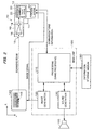
- FIG. 2 An example of the configuration of a game system (image generation system) that uses the handgun-shaped controller (broadly speaking: a position indication device) according to one embodiment of the present invention is shown in Fig. 2.
- a main unit 100 (such as a domestic game system) comprises a processing section 110, an image generation section 120, and a sound generation section 130.
- the processing section 110 performs processing such as restrict of the entire device and game processing, based on programs and data stored in an information storage medium 180 and communications information to and from a handgun-shaped controller 10.
- the functions of this processing section 110 could be implemented by hardware such as various different processors (such as a CPU or DSP) or an ASIC (gate array), or by a given program (game program).
- the processing performed by the processing section 110 includes: processing for setting various modes, processing for moving the game forward, processing for setting selection screens, processing for obtaining the position and rotational angle (about the X, Y, or Z axis) of an object (one or a plurality of primitive surfaces), processing for causing an object to move (motion processing) , processing for obtaining the position of a viewpoint (position of a virtual camera) and the angle-of-view thereof (rotational angle of the virtual camera), processing for disposing objects such as map objects in an object space, hit-check processing, processing for calculating game results (results and score), processing for enabling a plurality of players to play in a common game space, and game-over processing.
- the image generation section 120 performs various types of image processing in accordance with directions from the processing section 110, and generates game images (image signals) on a screen of a display device 140 (television receiver).
- the sound generation section 130 generates game sounds such as background music, sound effects, and voices in accordance with directions from the processing section 110, for output to a sound output device 132 (speaker).
- the functions of the image generation section 120 and the sound generation section 130 could be implemented by hardware such as various different processors or image-creation and sound-creation ASICs, or by a given program.
- the information storage medium 180 (a storage medium that can be used by a computer) is designed to store information such as programs and data, and its functions could be implemented by hardware such as an optical disk (CD or DVD), a magnetooptical (MO) disk, a magnetic disk, a hard disk, magnetic tape, or ROM.
- the processing section 110 performs the various types of processing in accordance with the present invention (embodiments of the invention) , based on the information stored in this information storage medium 180.
- the information storage medium 180 contains information (program or data) for implementing the means of the present invention (embodiments of the invention).
- program or data for implementing the means of the present invention could be transferred to the information storage medium 180 through a network from an information storage medium of a host device (server).
- the use of such an information storage medium at a host device (server) is also comprised within the scope of the present invention.
- the handgun-shaped controller 10 comprises an indicator body 12 (casing) formed in the shape of a handgun, a trigger 14 provided in a grip portion of the indicator body 12, an optical circuit formed of a lens 16 and an optical sensor 18 in the interior close to a muzzle 15 (light-incident aperture) of the indicator body 12, a light-proof case 50 that covers the lens 16 and the optical sensor 18 in such a manner that external light other than light from the muzzle 15 is not incident thereon, a processing section 20 that controls the entire handgun-shaped controller and performs calculations such as those to determine the indicated position, and a communications section 49 that functions as an interface with the main unit 100.
- processing section 20 and the communications section 49 could be implemented by hardware such as an ASIC, or by a combinations of various processors and software.
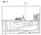
- the image generation section 120 of the main unit 100 generates an image signal and the CRT of the display device 140 is energized by the thus-generated image signal. This causes an object such as a target object 500 (an enemy character) to appear on the screen of the display device 140.
- a target object 500 an enemy character
- the screen flashes for just one frame. If the raster scan of the display device 140 passes through a detection area 142 that has been set in the vicinity of the position indicated by the handgun-shaped controller 10, the scanning beam at that point is focused by the lens 16 into the optical sensor 18. This causes the optical sensor 18 to output an optical detection signal.
- a position calculation section 30 of the processing section 20 calculates the position (X and Y coordinates) indicated by the handgun-shaped controller 10. During this time, the position calculation section 30 uses the synchronization signal comprised within the image signal from the main unit 100 to calculate the position indicated by the handgun-shaped controller 10.
- the processing section 110 of the main unit 100 performs a hit-check with the target object 500 shown on the screen, based on this indicated position information. In other words, if the indicated position matches the position of the target object 500, it is determined that a virtual shot has hit the target object; if they do not match, it is determined to be a miss.
- the lens 16 focuses light that is incident from an indicated position 150 within a screen 144, through the muzzle 15 (light-incident aperture).
- the optical sensor 18 detects the thus-focused light and outputs an optical detection signal to the processing section 20 in a later stage (see Fig. 2).
- the position (X and Y coordinates) within the screen 144 of the indicated position 150 are detected.
- the lens 16 and the optical sensor 18 are covered by the light-proof case 50 (broadly speaking: a light proof member) in such a manner that external light EL other than the light from the muzzle 15 is not incident on the lens 16 and the optical sensor 18. This makes it possible to prevent the problem of erroneous operation due to the optical sensor 18 reacting to the external light EL.
- the intensity of light from the indicated position 150 of the screen 144 is on the order of 300 lux, which is extremely low.
- the intensity of external light EL in the real world is extremely strong and can be on the order or ten to twenty thousand lux outdoors, by way of example.
- the indicator body 12 (casing) of the handgun-shaped controller of a material that is highly light-proof, for example, the problem of erroneous operation of the optical sensor 18 due to external light EL can be solved to a certain degree.
- the color of the indicator body 12 a pastel color that imparts a gentle neutral image, for example, it is necessary to arrange to use an organic colorant that is not very light-proof, for the plastic that forms the indicator body 12. If, however, a large proportion of organic colorant that is not very light-proof is used in this manner, the light-proofing capabilities of the indicator body 12 will be low and thus part of the external light EL will pass through the indicator body 12.
- the optical sensor 18, which is highly sensitive to react to the weak light from the indicated position 150, will therefore tend to react to the external light EL that has passed through the indicator body 12, raising the problem of erroneous operation. For that reason, it is difficult to use a pastel color as the color of the indicator body 12, and it is inevitable that a large ratio of highly light-proof inorganic colorant must be used.
- the color of the indicator body 12 is to be one of the currently fashionable "skeleton” (translucent) colors, substantially all of the external light EL will pass through the indicator body 12, making it impossible to expect the handgun-shaped controller to operate normally. It is therefore not possible to add a "skeleton" type of handgun-shaped controller to the product line-up, with the result that the product value of the handgun-shaped controller is reduced.
- embodiments of the invention ensure that the lens 16 and the optical sensor 18 are completely covered by the light-proof case 50, which is of a black pipe shape made of a material such as plastic with a large proportion of extremely light-proof carbon (ASB). External light EL is thereby prevented from being incident on the lens 16 and the optical sensor 18, making it possible to solve the problem of erroneous operation of the optical sensor 18.
- the light-proof case 50 which is of a black pipe shape made of a material such as plastic with a large proportion of extremely light-proof carbon (ASB). External light EL is thereby prevented from being incident on the lens 16 and the optical sensor 18, making it possible to solve the problem of erroneous operation of the optical sensor 18.
- the color of the indicator body 12 is made a pastel color or "skeleton" color, by way of example, the lens 16 and the optical sensor 18 are still covered by the light-proof case 50 so that the optical sensor 18 does not react to any external light EL, even if a large amount of external light EL does pass through the indicator body 12. It is therefore possible to use a highly design-worthy pastel color or a fashionable "skeleton” color for the color of the indicator body 12, enabling a huge increase in the product value of the handgun-shaped controller.
- a light-proof case 400 is provided in such a manner that it covers only the portion above the optical sensor 18 mounted on a board 70 (printed circuit board), as shown in Fig. 5.
- the light-proof case 400 of the comparative example of Fig. 5 does not cover the lens 16.
- the external light EL that passes through a light-incident aperture 402 that passes light from the lens 16 is also incident on the interior of the light-proof case 400, causing erroneous operation -of the optical sensor 18.
- the light-proof case 400 does not cover the surface on a signal terminal 19 side of the optical sensor 18.
- the board 70 on which the optical sensor 18 is mounted is formed of a resin that is not particularly light-proof, such as paper epoxy or paper phenol.
- the optical sensor 18 is covered by the light-proof case 50 in such a manner that all surfaces of the optical sensor 18, including the surface on which the signal terminals 19 are provided, are protected from the incidence of external light EL.
- the part of the board 70 on which the optical sensor 18 is mounted is covered by the pipe-shaped light-proof case 50, as shown in Fig. 6.
- the light-proof case 50 covers only the local portion on which the optical sensor 18 is mounted, not the entire board 70. It is therefore possible to make the light-proof case 50 smaller and also simplify the structure of the light-proof case 50, thereby reducing the cost of the handgun-shaped controller.
- the light-proof case 50 covers not only the optical sensor 18 but also the lens 16. It is therefore possible to prevent the problem that occurs with the comparative example of Fig. 5, in that external light EL passes through the light-incident aperture 402 and is incident on the interior of the light-proof case 400.
- the light-proof case 50 is formed from an assembly of a plurality of parts 50A and 50B that are connected together (the assembly could also comprise three or more parts) , as shown in Fig. 7.
- one side of the board 70 on which the optical sensor 18 is mounted is inserted (pressed) into a slit 52A provided in the part 50A.
- the parts 50A and 50B are then connected together, with the other side of the board 70 being inserted (pressed) into a slit 52B formed in the part 50B.
- FIG. 7 A different method from that of Fig. 7 could be considered, in which the optical sensor 18 is mounted on the board 70 after the board 70 has been covered by the light-proof case 50.
- a method would raise a problem in that the task of mounting the optical sensor 18 on the board 70 is complex and the workability of this assembly is low.
- the parts 50A and 50B are connected together with the optical sensor 18 already mounted on the board 70, so that the optical sensor 18 is covered by the light-proof case 50, enabling efficient prevention of problems such as that described above.
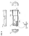
- F1 in Fig. 8 denotes a front view of the part 50A
- F2 and F3 denote side views thereof
- F4 denotes a plan view
- G1 in Fig. 9 denotes a front view of the part 50A
- G2 and G3 denote side views thereof
- G4 denotes a plan view.
- the cross-hatched portions of Figs. 8 and 9 denote the connection surfaces of the parts 50A and 50B.
- the broken lines denote the inner walls of the light-proof case 50 (the parts 50A and 50B).
- cut-out portions 54A and 54B are provided in the connection portions of the parts 50A and 50B (alternatively, cut-out portions could be provided on only one part), as shown in Figs. 7 to 9.
- cut-out portions 54A and 54B are designed to form through-holes for the signal terminals 19 of the optical sensor 18 when the parts 50A and 50B are connected together.
- the provision of the cut-out portions 54A and 54B in this manner ensures that it is possible to further simplify the process of covering the board 70 with the light-proof case 50 with the optical sensor 18 already mounted on the board 70.
- light-proof inner walls 56A and 56B are interposed between the optical sensor 18 and the board 70, as shown in Figs. 7 to 9.
- This double-walled structure of the light-proof inner walls 56A and 56B and light-proof outer walls 58A and 58B makes it possible to prevent the incidence of external light on the optical sensor 18 through the cut-out portions 54A and 54B. It is therefore possible to ensure that the light-proofing of the light-proof case 50 is even more secure.
- a protuberant portion is provided in the connection portions (the light-proof outer wall 58) of the part 50A of the light-proof case 50 and a fit portion (recess, depression) corresponding to that protuberant portion is provided in the connection portions of the other part 50B, as shown in Fig. 7.
- this embodiment is designed in such a manner that the protuberant portion of the part 50A and the fit (engagement) portion of the part 50B overlap each other, as seen from the viewpoint of the external light EL.
- connection surfaces 60A and 60B are provided on the connection portions of the parts 50A and 50B, extending in a direction that intersects the perpendicular to the outer surfaces of the connection portions. This ensures that external light EL that is incident through any gap in the connection portions of the parts 50A and 50B is shielded by the connection surfaces 60A and 60B that are formed of black plastic, enabling effective prevention of a state in which the external light EL is incident on the interior of the light-proof case 50.
- connection portions of the parts 50A and 50B makes it possible to improve the workability of the process of assembling the connections between the parts 50A and 50B, thus improving the accuracy with which the light-proof case 50 is assembled.
- connection portions of the parts 50A and 50B are not limited to those shown in Figs. 7 and 10B.
- the protuberant portion of the part 50A could have a tapered shape, and it is also possible to provide a plurality of these protuberant portions.
- the board 70 is inserted into the slits 52A and 52B of the parts 50A and 50B during the assembly process. There is therefore a problem that external light will intrude from the gaps between the board 70 and the slits 52A and 52B.
- a light-proof member is further provided to shield any external light that is incident from the gaps between the board 70 and the slits 52A and 52B.
- protuberant portions 62A, 64A, and 65A (or 62B, 64B, and 65B) of a triangular section are provided in the slit 52A (or 52B) that is provided in the part 50A (or 50B), with the thickness of the slit 52A (or 52B) being thinner than that of the board 70, as shown in Fig. 11A.
- the protuberant portions 62A, 64A, and 65A are deformed by pressing the board 70 into this slit 52A (or 52B), as shown in Figs. 11B, 11C, and 11D.
- Figs. 11B and 11C show the board 70 and the protuberant portion 62A (62B) as viewed from the direction H1 in Fig. 11A
- Fig. 11D shows the board 70 and the protuberant portions 64A and 65A (64B and 65B) as viewed from the direction H2 in Fig. 11A.
- a sealing member such as rubber packing
- a light-proof adhesive such as a black adhesive
- Part of the board is covered with the light-proof case in Fig. 7, but the configuration could also be such that the entire board is covered by the light-proof case.
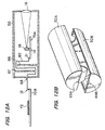
- the board is divided into a board 70A on which the optical sensor 18 is mounted and a board 70B on which other devices such as the IC 72 are mounted, as shown in Fig. 12A.
- the entire board 70A is covered by the light-proof case 50.
- a lead hole 68 for extracting lead wires 80 from the board 70A (lead wires that transfer signals from the signal terminals 19 of the optical sensor 18) is provided in the light-proof case 50.
- the light-proof case 50 is formed of a plurality of parts 50A and 50B in this case, as shown in Fig. 12B, it is possible for the optical sensor 18 to be covered by the light-proof case 50 in a state in which the optical sensor 18 has already been mounted on the board 70A.
- This configuration makes it possible to simplify the process of assembling the light-proof case 50, thus reducing the cost of the handgun-shaped controller.
- a light-proof member for shielding any external light that is incident from the lead hole 68 provided in the light-proof case 50 (a lead hole formed of cut-out portions 69A and 69B in Fig. 12B).
- each of light-proof inner walls 66 and 67 is formed of a material that is highly light-proof, in such a manner as to protrude towards opposite walls, as shown in Fig. 12A. External light that passes through the lead hole 68 is prevented from being incident on the optical sensor 18 and the lens 16 by disposing the light-proof inner walls 66 and 67 in such a manner as to overlap as seen from the direction of the lead hole 68.
- a sealing member such as rubber packing in the gaps between the lead hole 68 and the lead wires 80, in order to further increase the light-proofing of the light-proof case 50.
- the method of Fig. 12A is more advantageous than that of Fig. 12. This is because the method of Fig. 12A necessitates the addition of a step of soldering at the points indicated by I1 and I2, and it is also necessary to have two boards and provide the lead wires 80. In contrast thereto, the method of Fig. 7 does not necessitate a soldering step, the number of boards need not be more than one, and the lead wires 80 are also unnecessary, enabling reductions in the cost of the handgun-shaped controller.
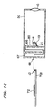
- the method shown in Fig. 13 could also be used as a method of covering the optical sensor 18 and the lens 16 completely with the light-proof case 50.
- the optical sensor 18 is attached directly to the light-proof case 50, instead of providing a board on which the optical sensor 18 is mounted.
- each of light-proof inner walls 66 and 67 is formed of a material that is highly light-proof, in such a manner as to protrude towards opposite walls, as shown in Fig. 13. External light that passes through the lead hole 68 is prevented from being incident on the optical sensor 18 and the lens 16 by disposing the light-proof inner walls 66 and 67 in such a manner as to overlap as seen from the direction of the lead hole 68.
- the method of Fig. 7 is more advantageous than that of Fig. 13. This is because the method of Fig. 13 necessitates the addition of a step of soldering at the points indicated by J1 and J2, and it is also necessary to provide the lead wires 80. In contrast thereto, the method of Fig. 7 does not necessitate a soldering step and the lead wires 80 are also unnecessary, enabling reductions in the cost of the handgun-shaped controller.
- the methods described with reference to Figs. 7, 12A, 12B, and 13 are particularly preferable as the method of covering the optical sensor and lens with a light-proof member (broadly speaking: light-proof case), but the present invention is not limited thereto and various modifications are possible.
- the method of Fig. 2 is used as the method of detecting the position indicated by the position indication device (broadly speaking: the handgun-shaped controller), but the present invention is not limited thereto.
- the present invention is applied to the use of a handgun-shaped controller, but it can also be applied to various other position indication devices such as game controllers other than handgun-shaped controllers.
- the present invention can also be applied to various other imaging systems such as large-scale attractions in which many players can participate, simulators, and multimedia terminals.
Landscapes
- Engineering & Computer Science (AREA)
- Multimedia (AREA)
- Human Computer Interaction (AREA)
- General Engineering & Computer Science (AREA)
- Theoretical Computer Science (AREA)
- Physics & Mathematics (AREA)
- General Physics & Mathematics (AREA)
- Switches Operated By Changes In Physical Conditions (AREA)
- Position Input By Displaying (AREA)
- Length Measuring Devices By Optical Means (AREA)
Abstract
Description
Claims (24)
- A position indication device for indicating a position within a screen of a display device, the position indication device comprising:an indicator body that indicates a position within a screen of a display device;a lens that is provided in the indicator body and focuses light that is incident from a position indicated by the indicator body through a light-incident aperture of the indicator body;an optical sensor that is provided in the indicator body and detects light focused by the lens; anda light-proof member that is provided in the indicator body and covers the lens and the optical sensor in such a manner that external light other than light from the light-incident aperture is not incident on the lens and the optical sensor.
- The position indication device as defined by claim 1,
wherein the light-proof member covers the optical sensor in such a manner as to prevent the incidence of external light to all surfaces of the optical sensor, including a surface on which a signal terminal of the optical sensor is provided. - The position indication device as defined by claim 1,
wherein the light-proof member covers at least a board portion on which the optical sensor is mounted, of a board for mounting the optical sensor. - The position indication device as defined by claim 2,
wherein the light-proof member covers at least a board portion on which the optical sensor is mounted, of a board for mounting the optical sensor. - The position indication device as defined by claim 1, wherein:the light-proof member is configured of an assembly of a plurality of parts; anda cut-out portion is provided in a connection portion between parts of the light-proof member, in order to form a through-hole for a signal terminal of the optical sensor.
- The position indication device as defined by claim 2, wherein:the light-proof member is configured of an assembly of a plurality of parts; anda cut-out portion is provided in a connection portion between parts of the light-proof member, in order to form a through-hole for the signal terminal of the optical sensor.
- The position indication device as defined by claim 3, wherein:the light-proof member is configured of an assembly of a plurality of parts; anda cut-out portion is provided in a connection portion between parts of the light-proof member, in order to form a through-hole for a signal terminal of the optical sensor.
- The position indication device as defined by claim 1, wherein:the light-proof member is configured of an assembly of a plurality of parts; anda protuberant portion is provided in a connection portion of a first part of the plurality of parts, and also a fit portion that fits with the protuberant portion is provided in a connection portion of a second part of the plurality of parts.
- The position indication device as defined by claim 2, wherein:the light-proof member is configured of an assembly of a plurality of parts; anda protuberant portion is provided in a connection portion of a first part of the plurality of parts, and also a fit portion that fits with the protuberant portion is provided in a connection portion of a second part of the plurality of parts.
- The position indication device as defined by claim 3, wherein:the light-proof member is configured of an assembly of a plurality of parts; anda protuberant portion is provided in a connection portion of a first part of the plurality of parts, and also a fit portion that fits with the protuberant portion is provided in a connection portion of a second part of the plurality of parts.
- The position indication device as defined by claim 5, wherein:the light-proof member is configured of an assembly of a plurality of parts; anda protuberant portion is provided in a connection portion of a first part of the plurality of parts, and also a fit portion that fits with the protuberant portion is provided in a connection portion of a second part of the plurality of parts.
- The position indication device as defined by claim 1, wherein:the light-proof member covers a board portion on which the optical sensor is mounted, of a board for mounting the optical sensor; anda second light-proof member is provided to prevent the incidence of the external light from a gap between the board and a slit provided in the light-proof member for the insertion of the board.
- The position indication device as defined by claim 2, wherein:the light-proof member covers a board portion on which the optical sensor is mounted, of a board for mounting the optical sensor; anda second light-proof member is provided to prevent the incidence of the external light from a gap between the board and a slit provided in the light-proof member for the insertion of the board.
- The position indication device as defined by claim 3, wherein:the light-proof member covers the board portion on which the optical sensor is mounted, of the board for mounting the optical sensor; anda second light-proof member is provided to prevent the incidence of the external light from a gap between the board and a slit provided in the light-proof member for the insertion of the board.
- The position indication device as defined by claim 5, wherein:the light-proof member covers a board portion on which the optical sensor is mounted, of a board for mounting the optical sensor; anda second light-proof member is provided to prevent the incidence of the external light from a gap between the board and a slit provided in the light-proof member for the insertion of the board.
- The position indication device as defined by claim 8, wherein:the light-proof member covers a board portion on which the optical sensor is mounted, of a board for mounting the optical sensor; anda second light-proof member is provided to prevent the incidence of the external light from a gap between the board and a slit provided in the light-proof member for the insertion of the board.
- The position indication device as defined by claim 12, wherein:the light-proof member is configured of an assembly of a plurality of parts; andthe second light-proof member is a protuberant portion that is deformed by the insertion of the board into the slit provided in each part of the light-proof member and seals the gap between the slit and the board.
- The position indication device as defined by claim 13, wherein:the light-proof member is configured of an assembly of a plurality of parts; andthe second light-proof member is a protuberant portion that is deformed by the insertion of the board into the slit provided in each part of the light-proof member and seals the gap between the slit and the board.
- The position indication device as defined by claim 14, wherein:the light-proof member is configured of an assembly of a plurality of parts; andthe second light-proof member is a protuberant portion that is deformed by the insertion of the board into the slit provided in each part of the light-proof member and seals the gap between the slit and the board.
- The position indication device as defined by claim 15, wherein:the light-proof member is configured of an assembly of a plurality of parts; andthe second light-proof member is a protuberant portion that is deformed by the insertion of the board into the slit provided in each part of the light-proof member and seals the gap between the slit and the board.
- The position indication device as defined by claim 16, wherein:the light-proof member is configured of an assembly of a plurality of parts; andthe second light-proof member is a protuberant portion that is deformed by the insertion of the board into the slit provided in each part of the light-proof member and seals the gap between the slit and the board.
- The position indication device as defined by claim 1, wherein:the light-proof member covers the entirety of a board on which the optical sensor is mounted; anda second light-proof member is provided to prevent the incidence of external light from a gap between a lead wire from the board and a lead hole provided in the light-proof member for the extraction of the lead wire.
- The position indication device as defined by claim 1, wherein:the optical sensor is installed directly within the light-proof member; anda second light-proof member is provided to prevent the incidence of external light from a gap between a lead wire from a signal terminal of the optical sensor and a lead hole provided in the light-proof member for the extraction of the lead wire.
- A computer-usable information storage medium used in a game system that comprises:wherein the information storage medium comprises a program for implementing the above means on a computer.the position indication device as defined by any one of claims 1 to 23;game processing means that receives information from the position indication device and performs game processing based on the detected indicated position; andimage generation means that generates a game image in accordance with the game processing performed by the game processing means,
Applications Claiming Priority (3)
| Application Number | Priority Date | Filing Date | Title |
|---|---|---|---|
| JP2000192615A JP2002007072A (en) | 2000-06-27 | 2000-06-27 | Position pointing device and information storage medium |
| JP2000192615 | 2000-06-27 | ||
| PCT/JP2001/005500 WO2002001340A1 (en) | 2000-06-27 | 2001-06-27 | Position indication device, and information storage medium |
Publications (3)
| Publication Number | Publication Date |
|---|---|
| EP1296217A1 true EP1296217A1 (en) | 2003-03-26 |
| EP1296217A4 EP1296217A4 (en) | 2003-08-20 |
| EP1296217B1 EP1296217B1 (en) | 2008-04-16 |
Family
ID=18691725
Family Applications (1)
| Application Number | Title | Priority Date | Filing Date |
|---|---|---|---|
| EP01945631A Expired - Lifetime EP1296217B1 (en) | 2000-06-27 | 2001-06-27 | Position indication device, and information storage medium |
Country Status (5)
| Country | Link |
|---|---|
| US (1) | US6926610B2 (en) |
| EP (1) | EP1296217B1 (en) |
| JP (1) | JP2002007072A (en) |
| DE (1) | DE60133646T2 (en) |
| WO (1) | WO2002001340A1 (en) |
Families Citing this family (11)
| Publication number | Priority date | Publication date | Assignee | Title |
|---|---|---|---|---|
| US6600497B1 (en) * | 1999-11-15 | 2003-07-29 | Elliot A. Gottfurcht | Apparatus and method to navigate interactive television using unique inputs with a remote control |
| US7796116B2 (en) | 2005-01-12 | 2010-09-14 | Thinkoptics, Inc. | Electronic equipment for handheld vision based absolute pointing system |
| JP4794957B2 (en) * | 2005-09-14 | 2011-10-19 | 任天堂株式会社 | GAME PROGRAM, GAME DEVICE, GAME SYSTEM, AND GAME PROCESSING METHOD |
| JP4773170B2 (en) * | 2005-09-14 | 2011-09-14 | 任天堂株式会社 | Game program and game system |
| JP4684147B2 (en) | 2006-03-28 | 2011-05-18 | 任天堂株式会社 | Inclination calculation device, inclination calculation program, game device, and game program |
| US8913003B2 (en) | 2006-07-17 | 2014-12-16 | Thinkoptics, Inc. | Free-space multi-dimensional absolute pointer using a projection marker system |
| US8096880B2 (en) * | 2006-08-15 | 2012-01-17 | Nintendo Co., Ltd. | Systems and methods for reducing jitter associated with a control device |
| US9176598B2 (en) | 2007-05-08 | 2015-11-03 | Thinkoptics, Inc. | Free-space multi-dimensional absolute pointer with improved performance |
| JP5519168B2 (en) * | 2009-03-27 | 2014-06-11 | 能美防災株式会社 | Fire detector |
| US20140364180A1 (en) * | 2013-06-10 | 2014-12-11 | Edward Olivar | Predator 80 systems |
| JP2015184391A (en) * | 2014-03-21 | 2015-10-22 | 大木 光晴 | Image display method, device, and program |
Family Cites Families (14)
| Publication number | Priority date | Publication date | Assignee | Title |
|---|---|---|---|---|
| JPS5630384Y2 (en) * | 1977-04-19 | 1981-07-20 | ||
| US4100774A (en) | 1977-05-18 | 1978-07-18 | Emhart Industries, Inc. | Lockset having improved torque blade construction |
| GB2160298B (en) * | 1984-06-14 | 1987-07-15 | Ferranti Plc | Weapon aim-training apparatus |
| JPH067389Y2 (en) | 1986-12-01 | 1994-02-23 | アルプス電気株式会社 | Coordinate input device |
| US4844475A (en) * | 1986-12-30 | 1989-07-04 | Mattel, Inc. | Electronic interactive game apparatus in which an electronic station responds to play of a human |
| JP3153603B2 (en) * | 1991-12-28 | 2001-04-09 | 任天堂株式会社 | Gun device used in shooting game system |
| JP2681454B2 (en) * | 1995-02-21 | 1997-11-26 | コナミ株式会社 | Shooting game device |
| JPH08294582A (en) | 1995-04-27 | 1996-11-12 | Taito Corp | Simulated gun for game machine and game machine using the same |
| JP3140971B2 (en) | 1996-10-17 | 2001-03-05 | 株式会社ナムコ | Game controller |
| JP3856403B2 (en) * | 1996-10-31 | 2006-12-13 | 株式会社バンダイナムコゲームス | Position indicating device for image display device and shooting simulation device using the same |
| JPH10165642A (en) | 1996-12-13 | 1998-06-23 | Konami Co Ltd | Dummy gun for shooting game machine |
| TW357101B (en) * | 1996-12-17 | 1999-05-01 | Konami Co Ltd | Shooting video game machine and shooting result presentation method |
| US6146278A (en) * | 1997-01-10 | 2000-11-14 | Konami Co., Ltd. | Shooting video game machine |
| JP3804328B2 (en) * | 1999-03-02 | 2006-08-02 | 株式会社セガ | Image processing apparatus and image processing method |
-
2000
- 2000-06-27 JP JP2000192615A patent/JP2002007072A/en not_active Withdrawn
-
2001
- 2001-06-27 WO PCT/JP2001/005500 patent/WO2002001340A1/en not_active Ceased
- 2001-06-27 US US10/069,172 patent/US6926610B2/en not_active Expired - Fee Related
- 2001-06-27 DE DE60133646T patent/DE60133646T2/en not_active Expired - Lifetime
- 2001-06-27 EP EP01945631A patent/EP1296217B1/en not_active Expired - Lifetime
Also Published As
| Publication number | Publication date |
|---|---|
| EP1296217B1 (en) | 2008-04-16 |
| DE60133646D1 (en) | 2008-05-29 |
| US20020165030A1 (en) | 2002-11-07 |
| EP1296217A4 (en) | 2003-08-20 |
| US6926610B2 (en) | 2005-08-09 |
| JP2002007072A (en) | 2002-01-11 |
| WO2002001340A1 (en) | 2002-01-03 |
| DE60133646T2 (en) | 2009-05-28 |
Similar Documents
| Publication | Publication Date | Title |
|---|---|---|
| EP1296217B1 (en) | Position indication device, and information storage medium | |
| JP3934658B2 (en) | Position detection system | |
| EP0728503B1 (en) | A shooting game machine | |
| JP3748271B2 (en) | Shooting game equipment | |
| WO1998017361A1 (en) | Game controller and information storage medium | |
| JP3422383B2 (en) | Method and apparatus for detecting relative position between video screen and gun in shooting game machine | |
| CN110959098B (en) | Darts game device | |
| JP2002298145A (en) | Position detecting device and attitude detecting device | |
| WO2004040229A3 (en) | Target system and method for ascertaining target impact locations of a projectile | |
| US20110187638A1 (en) | Interactive module applied in 3D interactive system and method | |
| US20050026703A1 (en) | Position detection system, game machine, program, and information storage medium | |
| US20020154092A1 (en) | Position pointing device, program, and pointed position detecting method | |
| US20030096649A1 (en) | Billiard game input device, billiard game system, game input device, and computer program | |
| GB2354580A (en) | Determining the position of a spotlight | |
| US20020004419A1 (en) | Photographing game machine, photographing game processing method and information storage medium | |
| JPH10249065A (en) | Shooting video game device | |
| GB2457674A (en) | Determining the time and location of an event, for example whether a ball hit a bat in cricket | |
| US20020160839A1 (en) | Game system and game method | |
| US20090305198A1 (en) | Gunnery training device using a weapon | |
| JP2573983B2 (en) | Recognition method of dice eyes used in game | |
| JPH1023298A (en) | Image pickup method and device using the image pickup method | |
| JP2001340636A (en) | Shooting game device, shooting game processing method, and information storage medium | |
| JP4900914B2 (en) | Program, information storage medium, and image generation system | |
| JP2019033497A (en) | Information processing system, control method therefor, and computer program | |
| KR100426295B1 (en) | Image processing unit and game machine |
Legal Events
| Date | Code | Title | Description |
|---|---|---|---|
| PUAI | Public reference made under article 153(3) epc to a published international application that has entered the european phase |
Free format text: ORIGINAL CODE: 0009012 |
|
| 17P | Request for examination filed |
Effective date: 20020422 |
|
| AK | Designated contracting states |
Kind code of ref document: A1 Designated state(s): AT BE CH CY DE DK ES FI FR GB GR IE IT LI LU MC NL PT SE TR |
|
| A4 | Supplementary search report drawn up and despatched |
Effective date: 20030704 |
|
| RBV | Designated contracting states (corrected) |
Designated state(s): DE FR GB |
|
| RAP1 | Party data changed (applicant data changed or rights of an application transferred) |
Owner name: TAMURA CORPORATION Owner name: NAMCO BANDAI GAMES INC. |
|
| RAP1 | Party data changed (applicant data changed or rights of an application transferred) |
Owner name: TAMURA CORPORATION Owner name: NAMCO BANDAI GAMES INC. |
|
| GRAP | Despatch of communication of intention to grant a patent |
Free format text: ORIGINAL CODE: EPIDOSNIGR1 |
|
| GRAS | Grant fee paid |
Free format text: ORIGINAL CODE: EPIDOSNIGR3 |
|
| GRAA | (expected) grant |
Free format text: ORIGINAL CODE: 0009210 |
|
| AK | Designated contracting states |
Kind code of ref document: B1 Designated state(s): DE FR GB |
|
| RAP1 | Party data changed (applicant data changed or rights of an application transferred) |
Owner name: NAMCO BANDAI GAMES INC. |
|
| REF | Corresponds to: |
Ref document number: 60133646 Country of ref document: DE Date of ref document: 20080529 Kind code of ref document: P |
|
| ET | Fr: translation filed | ||
| PLBE | No opposition filed within time limit |
Free format text: ORIGINAL CODE: 0009261 |
|
| STAA | Information on the status of an ep patent application or granted ep patent |
Free format text: STATUS: NO OPPOSITION FILED WITHIN TIME LIMIT |
|
| 26N | No opposition filed |
Effective date: 20090119 |
|
| PGFP | Annual fee paid to national office [announced via postgrant information from national office to epo] |
Ref country code: DE Payment date: 20120620 Year of fee payment: 12 |
|
| PGFP | Annual fee paid to national office [announced via postgrant information from national office to epo] |
Ref country code: FR Payment date: 20120619 Year of fee payment: 12 Ref country code: GB Payment date: 20120627 Year of fee payment: 12 |
|
| GBPC | Gb: european patent ceased through non-payment of renewal fee |
Effective date: 20130627 |
|
| REG | Reference to a national code |
Ref country code: FR Ref legal event code: ST Effective date: 20140228 |
|
| REG | Reference to a national code |
Ref country code: DE Ref legal event code: R119 Ref document number: 60133646 Country of ref document: DE Effective date: 20140101 |
|
| PG25 | Lapsed in a contracting state [announced via postgrant information from national office to epo] |
Ref country code: DE Free format text: LAPSE BECAUSE OF NON-PAYMENT OF DUE FEES Effective date: 20140101 Ref country code: GB Free format text: LAPSE BECAUSE OF NON-PAYMENT OF DUE FEES Effective date: 20130627 |
|
| PG25 | Lapsed in a contracting state [announced via postgrant information from national office to epo] |
Ref country code: FR Free format text: LAPSE BECAUSE OF NON-PAYMENT OF DUE FEES Effective date: 20130701 |