BACKGROUND OF THE INVENTION
Suppliers of process plants in the process industries often design and construct
plants to the specifications of each buyer on a built-to-order custom basis. This is
common practice when the process plants are low-volume, highly-specialized, high-cost
products. Such plants are utilized in process industries such as petroleum refining,
chemicals, industrial gases, pharmaceuticals, primary metals, and food processing.
Design and engineering costs for such plants are significant because much of the design
and engineering work is done on a one-off basis and cannot be reused for future plants.
Suppliers of process plants attempt to standardize component selection and
design efforts as much as possible in order to offer cost-competitive product lines to
potential buyers. Greater standardization of plant components, which brings the benefits
of mass production to the supplier, can be contrary to the buyer's desire for
customization and maximum flexibility. Because the cost of engineering design is a
major component of the capital cost of a large process plant, the supplier has a
significant incentive to standardize engineering design work in order to offer a
cost-competitive plant which performs to the buyer's specifications. The challenge to the
process plant supplier is to balance a maximum selection of process plants in each
product line with a minimum number of standard components used in process plant
design, while at the same time ensuring acceptable choices and flexibility for the buyer.
When this is achieved, improved competitive position and profitability will be realized by
the supplier, while maximum value will be realized by the buyer.
The example embodiments of the present invention address the need for an
engineering design approach to provide process plant product lines which satisfy buyers'
requirements while minimizing engineering design costs by maximizing the use of
repeatable engineered components in each plant design.
BRIEF SUMMARY OF THE INVENTION
The invention relates to a method for process plant design which comprises
(a) preparing a detailed design for a process plant in a product line including a detailed
design of at least one engineered component, and (b) preparing a detailed design for
another process plant in a different product line wherein the detailed design of the at
least one engineered component of (a) is reused in (b).
In an embodiment of the invention, the method may include:
This embodiment also may include, as part of (d), modifying the general process designs
for one or more of the process plants to optimize the combination of general process
designs and the minimum number of repeatable engineered components and the
process attributes thereof. Further, the embodiment may include preparing additional
detailed designs of process plants in the process plant product lines wherein each
additional detailed process plant design utilizes at least one previous detailed design of a
repeatable engineered component. A detailed design may be prepared for at least one
additional repeatable engineered component.
The method described above may further include storing design information in
electronic format from previous detailed designs of repeatable engineered components
in a computer-based document and data management system for future use in additional
detailed designs of process plants in the process plant product lines.
The future general process design of each process plant may allow acceptable
projections of plant capital cost and operating efficiency. The process plant product lines
may comprise cryogenic air separation plants, hydrogen production plants, or gas
separation pressure swing adsorption plants. The pressure swing adsorption plants may
be designed for the separation of air.
The repeatable engineered components may include engineered components
selected from the group consisting of feed air cleanup systems, main heat exchangers,
reboilers, distillation column sections, cold enclosures, main air compression systems, air
booster compressors, gas expanders, recycle compressors, process control systems,
warm piping, cold piping, cryogenic liquid pumps, and product gas compressors. Each
distillation column section may be defined by the column diameter and the height of
vapor-liquid mass transfer devices. Each main air compression system may be defined
by maximum air flow rate and discharge pressure. Each gas expander may be defined
gas flow rate and pressure ratio.
The process plant product line may include air separation plants which produce
one or more products selected from the group consisting of oxygen gas containing 95-99
vol% oxygen, oxygen gas containing up to 99.8 vol% oxygen, liquid oxygen, nitrogen gas
containing between about 0.1 to 1 parts per million by volume non-nitrogen components,
nitrogen gas containing up to about 0.5 parts per billion by volume non-nitrogen
components, and liquid nitrogen.
The invention also relates to a method for process plant design which comprises:
The future general process design of each process plant preferably allows acceptable
projections of plant capital cost and operating efficiency.
The method may further comprise preparing a general process design of a
process plant suitable for a cost proposal, wherein the general process design
comprises:
This method may further comprise utilizing the general process design of the selected
process plant to prepare a cost proposal for the potential buyer. The method may further
comprise preparing a detailed design of the selected process plant which includes
utilizing the design information of (e) above for the repeatable engineered components
selected in (3) above.
The invention also relates to a method for process plant design which comprises:
The invention may include a method for cryogenic air separation plant design
which comprises:
The repeatable engineered components may comprise engineered components selected
from the group consisting of feed air cleanup systems, main heat exchangers, reboilers,
distillation column sections, cold enclosures, main air compression systems, air booster
compressors, gas expanders, recycle compressors, process control systems, warm
piping, cold piping, cryogenic liquid pumps, and product gas compressors. Each
distillation column section may be defined by the column diameter and the height of
vapor-liquid mass transfer devices. Each main air compression system may be defined
by maximum air flow rate and discharge pressure. Each gas expander may be defined
gas flow rate and pressure ratio.
The process plant product line may include air separation plants which produce
one or more products selected from the group consisting of oxygen gas containing 95-99
vol% oxygen, oxygen gas containing up to 99.8 vol% oxygen, liquid oxygen, nitrogen gas
containing between about 0.1 to 1 parts per million by volume non-nitrogen components,
nitrogen gas containing up to about 0.5 parts per billion by volume non-nitrogen
components, and liquid nitrogen.
In another aspect, the invention may include a system for process plant design
which comprises:
The database may be stored at the workstation. The system may further comprise a
home server and a database server in communication with the home server, wherein the
database resides on the database server. The system also may include a satellite
server in communication with the home server and the database server, wherein another
workstation is connected to the satellite server.
The invention also relates to a method for cryogenic air separation plant design
which comprises:
BRIEF DESCRIPTION OF SEVERAL VIEWS OF THE DRAWINGS
Fig. 1 is a flowchart illustrating an exemplary design method according to the
present invention.
Fig. 2 shows a block diagram of a exemplary computer-based document and data
management system.
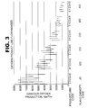
Fig. 3 is a graphic depiction of the ranges of oxygen production capacity for each
plant case and nominal plant size for product line codes 0 through 5 of the example
embodiment of the present invention.
Fig. 4 is a graphic depiction of the ranges of nitrogen production capacity for each
product line and nominal plant size for product line codes 6 through 9 of the example
embodiment of the present invention.
Fig. 5 is a schematic flowsheet for the cryogenic air separation process cycle for
product line code 0 according to the example embodiment of the present invention.
Fig. 6 is a schematic flowsheet for the cryogenic air separation process cycle for
product line code 1 according to the example embodiment of the present invention.
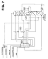
Fig. 7 is a schematic flowsheet for the cryogenic air separation process cycle for
product line code 2 according to the example embodiment of the present invention.
Fig. 8 is a schematic flowsheet for the cryogenic air separation process cycle for
product line code 3 according to the example embodiment of the present invention.
Fig. 9 is a schematic flowsheet for the cryogenic air separation process cycle for
product line code 4 according to the example embodiment of the present invention.
Fig. 10 is a schematic flowsheet for the cryogenic air separation process cycle for
product line code 5 according to the example embodiment of the present invention.
Fig. 11 is a schematic flowsheet for the cryogenic air separation process cycle for
product line codes 6 and 7 according to the example embodiment of the present
invention.
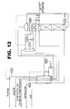
Fig. 12 is a schematic flowsheet for the cryogenic air separation process cycle for
product line code 8 according to the example embodiment of the present invention.
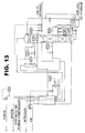
Fig. 13 is a schematic flowsheet for the cryogenic air separation process cycle for
product line code 9 according to the example embodiment of the present invention.
Fig. 14 is a schematic illustration of the engineered components in the machinery,
cold process, and warm process categories of an air separation plant according to an
example embodiment of the present invention.
DETAILED DESCRIPTION
The present invention relates to a method and strategy to provide multiple
process plant product lines from a common set of engineered components. In the
example embodiment, the engineered components may include engineered systems,
engineered subsystems, and equipment. The example embodiment provides the
framework for the development, design, manufacture, supply, and product management
of process plants which achieves costs not previously attainable with such low-volume,
high-variability, high-cost products. Detailed designs of engineered components, after
initial completion, may be reused across different product lines as well as within the
same product lines. In the following, a method for providing cryogenic air separation
process plants is presented for illustrative purposes.
The production of industrial gases such as oxygen, nitrogen, argon, hydrogen,
and synthesis gas requires highly-specialized, capital-intensive process plants. The
industrial gas industry is similar to other process industries such as petroleum refining,
chemicals, pharmaceuticals, primary metals, and food processing in that the process
plants utilized in these industries typically are low-volume, highly-specialized, high-cost
products provided by selected suppliers.
The cryogenic separation of air to provide oxygen and nitrogen products at
various purities and pressures is a well-known technology. Traditionally, the suppliers
of medium-sized cryogenic air separation plants in the range of 40 to 500 metric
tons/day (MT/D) have tended to design plants on a one-off, design-to-order basis.
Previous designs have been used when possible as templates or guides to reduce the
amount of engineering design effort required for plants within a product line. As
competition in the industry has increased, providers of air separation plants have moved
towards standardization in which product lines have been developed wherein each
product line offers a range of sizes for a given plant design. Typically, limited options
have been offered to the buyer. This approach has been relatively successful for
smaller plants within product lines when there is a reasonable demand for particular
plant sizes and features.
Products and product strategies have been subjected to extensive value
engineering in the industry to achieve lowest cost and maximum value for the buyer.
Aside from significant technology breakthroughs, there are few techniques which air
separation plant providers can use to reduce capital costs further without substantially
sacrificing performance and operating costs. Thus there is need for a new approach to
the supply of cryogenic plants in order to achieve significantly lower capital costs.
The cryogenic separation of air is a well-known and highly-developed technology
particularly well-suited to higher production rates and higher product purities than other
known air separation methods. A wide range of cryogenic air separation process cycles
has been developed in the industry over the years. Sufficient flexibility can be
incorporated in the designs of plants in individual product lines to enable the offering of
a wide range of standard options to the buyer in order to match the customer's
requirements. This is known as "mass customization", which attempts to balance
standardization against design-to-order flexibility within an individual product line.
In accordance with an example embodiment of the present invention, a plurality
of process plant product lines may be defined. A process plant may include an
integrated group of engineering components configured to convert one or more input
feed fluids into one or more product fluids of predefined properties.
A general process design then may be prepared for each process plant product
line. In accordance with the example embodiment, a product line or a process plant
product line may include a set of process plants wherein the process plants are of
similar general process design that may differ in a process parameter such as flow
capacity. Plants in different product lines may utilize different general process designs.
A general process design may set forth key process parameters for a process plant
product line such as capacity, product purity, plant configuration (e.g., the general flow
sheet), and related information.
The general process designs may be divided into a number of engineered
components. An engineered component may include, for example, engineered
systems, engineered subsystems, and pieces of equipment. An engineered system
may include a complete assembly of equipment which performs a specific process
function, e.g., a main air compression system. An engineering subsystem may include
specific hardware which is part of an engineered system, for example, the process
piping and instrumentation associated with a main air compression system. A piece of
equipment may include a specific machine or fabricated item which performs a specific,
individual function, for example, a compressor used in a main air compression system.
From the engineered components, a minimum number of repeatable engineered
components and the process attributes thereof which are required for future general
process designs may be determined. A repeatable engineered component may include,
for example, an engineered component which has been designed in detail for use in a
first process plant, wherein the design can be reused with minimal alteration in different
process plants. The different process plants can be in the same product line as the first
process plant, or in different product lines than the first process plant. Process
attributes may include, for example, ranges of operating characteristics such as
compressor suction and discharge pressures, volumetric throughput, cooling water
requirements, specific power, and other appropriate characteristics.
According to the example embodiment, a detailed design of a process plant in a
process plant product line can be prepared. The detailed design of the process plant
may include, for example, selecting specific repeatable engineered components and the
process attributes thereof from the minimum number of repeatable engineered
components, and preparing a detailed design for one or more of the repeatable
engineered components selected. A detailed process design may include a general
process design for a process plant which is further developed wherein engineered
systems, engineered subsystems, and pieces of equipment are fully specified in terms
of functionality. A detailed design may include a detailed process design for a process
plant which is further developed wherein each engineered system, engineered
subsystem, and piece of equipment is completely specified in sufficient detail to allow
procurement and manufacture.
A detailed design of a process plant in another process plant product line then
may be designed. The detailed design may include the selection of specific engineered
components and the process attributes thereof from the minimum number repeatable
components determined. At least one of the repeatable engineered components
selected may be identical to one of the repeatable engineered components selected in
connection with the detailed design of the process plant in the first process plant
product line. According to the example embodiment, the detailed design of the
repeatable engineered component prepared in connection with the process plant in the
first process plant product line may be reused in the detailed design of the process plant
in the second process plant product line.
The following description applies the example embodiment of the invention to
the design of cryogenic air separation plants for the production of oxygen and nitrogen,
both gaseous and liquid, at various purities and pressures.
In the example embodiment, information developed in the project steps is
generated in electronic form by computer-based design tools. This information
includes, for example, process flow diagrams, piping and instrumentation diagrams,
data spreadsheets, vendor-provided documents, cost analyses, and engineering scope
reports. The information in electronic form may be manipulated for input, storage, and
retrieval by means of a computer-based document and data management system. This
system may be the sole repository for all product and design information, and may be
accessible for use by different design personnel in different locations. Central storage
of all design information in electronic form maintains product line integrity and allows
efficient communication among design personnel.
The project steps summarized above are described in detail below and are
depicted schematically in the flowchart of Fig. 1, which illustrates the order of the steps
and the manipulation of the electronic design information generated therein. Fig. 2 is an
exemplary electronic document and data management system which may be used for
the manipulation, storage, and retrieval of the electronic design information generated
by the project steps of Fig. 1.
The system of Fig. 2 comprises home server 201, satellite server 203, and
database server 205. Home server 201 may include electronic data management
system 207, electronic data management software 209, and data file 211. Satellite
server 203 includes electronic data management system 213, electronic data
management software 215, and data file 217. Database 206 resides on database
server 205 and may utilize, for example, software such as Microsoft SQL 7 SP1. Home
server 201 and satellite server 203 may be separated by a considerable distance and
data may be transferred between these servers by high speed network link 219. Files
217 and 211 may be shared or parallel files which optionally are replicated at regular
time intervals, for example, daily. Database server 205 may be connected to home
server 201 by local network link 220.
Users at personal computer or workstation 221 may execute the project steps of
Fig. 1 utilizing software which resides on that personal computer or workstation in
conjunction with software residing on home server 201. Likewise, users at personal
computer or workstation 223 may execute the project steps of Fig. 1 utilizing software
which resides on that personal computer or workstation in conjunction with software
residing on satellite server 203. Personal computers or workstations 221 and 223 may
be connected to home server 201 and satellite server 203 by local network links 225
and 227 respectively. Additional personal computers or workstations (not shown) may
be connected to home server 201 and satellite server 203 by local network links (not
shown) and may be operated in the same manner as personal computers or
workstations 221 and 223.
Optionally, personal computer or workstation 229 may execute project steps of
Fig. 1 utilizing software which resides on terminal server 231 in conjunction with
software which resides on home server 201. Personal computer or workstation 229
may be connected to terminal server 231 by dialup link 233 and terminal server 231
may be linked to home server by local network link 235. Additional personal computers
or workstations (not shown) may be linked with home server 201 in like manner.
Electronic design data and information generated by users executing the project
steps of Fig. 1 may be manipulated by electronic data management system 207 and
electronic data management software 209, which are resident on home server 201, and
also by electronic data management system 213 and electronic data management
software 215, which are resident on satellite server 203. The electronic design data and
information may be stored in or retrieved from individual data files 7, 13, and 14 located
on home server 201 and/or parallel individual data files 7', 13', and 14' located on
satellite server 203. Files 7 and 7' may be shared or parallel files which optionally are
replicated at regular time intervals, for example, daily. Likewise, files 13 and 13' may be
shared or parallel files which optionally are replicated at regular time intervals. In similar
fashion, files 14 and 14' may be shared or parallel files which optionally are replicated at
regular time intervals.
Referring now to Fig. 1, the method of the present invention begins at project
inception 1 and proceeds as described below.
a) Define a plurality of process plant product lines
The first step in the example process,
step 3 in Fig. 1, is the definition of the
generic process plant product lines which cover the market for these plants based on an
understanding of buyers' requirements. According to the example embodiment, the
defined generic process plant product lines are shown in Table 1 below.
| Generic Product Lines |
| Product Line Code | Gaseous Oxygen | LOX | Gaseous Nitrogen | LIN |
| | Purity, vol % O2 | Pressure, barg | % Make | Product Purity | Pressure | % Make | % Make | |
| 0 | 95-97 | 1.1 | 0-3 |
| 1 | 95-97 | 1.1 | 0-10 |
| 2 | 95-97 | 1.3 | 0-10 | ppm | ≤5 barg | 0-15 | 0-10* |
| 3 | 95-97 | 1.3 | 0-10 | ppm | LP | 15-50 | 0-10* |
| 4 | up to 99.8 | 1.3 | 0-10 | ppm | ≤5 barg | 0-15 | 0-10* |
| 5 | up to 99.8 | 1.3 | 0-10 | ppm | LP | 15-50 | 0-10* |
| 6 | | | | ppm | 4-11 barg | 100 | 0-10 |
| 7 | | | | 100 ppb | 4-11 barg | 100 | 0-10 |
| 8 | | | | ppb | 4-11 barg | 100 | 0-10 |
| 9 | | 0.4 | 0-1 (UHP) | ppb | 4-11 barg | 100 | 0-10 |
| LOX = liquid oxygen |
| LIN = liquid nitrogen |
* Plant will make up to 10% LOX, 10% LIN, or a combined total % make up to10%
% make is defined as the % of the total plant oxygen make |
| LOX and LIN make is based on total oxygen make |
| Gaseous nitrogen make is based on total feed air flow |
| LP = just above atmospheric pressure |
| Nitrogen product purity is defined as the total concentration of non-nitrogen contaminants |
| ppm = typically 1-5 parts per million (volume) |
| ppb = typically 1-5 parts per billion (volume) |
| UHP = ultra high purity oxygen containing typically 1-5 ppb non-oxygen contaminants |
In this example, each of the
process plant cases 0 through 9 is considered a
single product line, and each of these product lines includes individual plants having
selected sizes, products, and production rates. Specific plant production rates or
capacities are defined for the each of the product lines. These nominal production
ranges or plant sizes in combination with the generic process plant product lines of
Table 1 define the main process plant product lines according to the example
embodiment. Exemplary nominal plant product flow ranges are summarized in Table 2
below.
| Nominal Plant Production Ranges |
| Plant Capacity Code | Main Product Gas | Nominal Production Range, Nm3/hr |
| AO | Oxygen | 670-1500 |
| BO | Oxygen | 1000-2140 |
| CO | Oxygen | 1430-3140 |
| DN | Nitrogen | 1880-3600 |
| EO | Oxygen | 2000-4500 |
| FN | Nitrogen | 2670-5200 |
| GO | Oxygen | 2640-5500 |
| HN | Nitrogen | 3870-7470 |
| JO | Oxygen | 3900-8360 |
| KN | Nitrogen | 4270-8470 |
| LN | Nitrogen | 6930-13470 |
In this example, the complete process plant product line may be defined from the
information in Tables 1 and 2, and the main product line matrix may be generated as
shown in Table 3 below.
| Main Process Plant Product Line Matrix |
| Plant Capacity Code (Table 2) | Product Line Code (Table 1) |
| | 0 | 1 | 2 | 3 | 4 | 5 | 6 | 7 | 8 | 9 |
| AO | X | X | X | X | X | X |
| BO | X | X | X | X | X | X |
| CO | X | X | X | X | X | X |
| DN | | | | | | | X | X | X | X |
| EO | X | X | X | X | X | X |
| FN | | | | | | | X | X | X | X |
| GO | X | X | X | X | X | X |
| HN | | | | | | | X | X | X | X |
| JO | X | X | X | X | X | X |
| KN | | | | | | | X | X | X | X |
| LN | | | | | | | X | X | X | X |
In addition to the main process plant product lines summarized above, a
supplemental product line may be defined for high pressure oxygen product which is
provided by pumped liquid oxygen (LOX) cycles. This exemplary supplemental high
pressure oxygen product line may be summarized in the matrix given in Table 4 below.
| High Pressure Oxygen Process Plant Product Line Matrix |
| Plant Capacity Code (Table 2) | Product Line Code (Table 1) |
| | 1 | 2 | 3 | 4 | 5 |
| AO | X | X | X | X | X |
| BO | X | X | X | X | X |
| CO | X | X | X | X | X |
| EO | X | X | X | X | X |
| GO | X | X | X | X | X |
| JO | X | X | X | X | X |
In addition to the process plants described above, four additional plants may be
defined which are variants of product line codes 0, 2, 3, 4, and 5 of Table 1. In these
additional plant options, no liquid is produced, and gaseous nitrogen make can be up to
20% greater than shown in Table 1. These correspond to plants identified by plant
capacity codes AO, BO, CO, and EO.
The entire family of example process plants in the product lines may be defined
by the indicated combinations of plant capacity and product line codes in Tables 3 and 4
above.
The process plants described above may be designated in terms of the nominal
maximum plant production rates. In actual operation, however, each individual plant is
designed to operate over a range of production rates to allow the increases and
decreases in production rates which may occur in actual plant operation. Fig. 3 shows
the oxygen plant production ranges for the example product line codes 0 through 5 given
above in Tables 1, 2, and 3. Fig. 4 shows the corresponding information for the example
nitrogen product line codes 5 through 9. It is seen that each plant can operate nominally
over a range of production capacities. In this example, the selected engineered
components are defined to allow each plant to operate over the indicated ranges of
production rates at acceptable operating efficiency. Operating efficiency of a process
plant may include the total expendable cost of plant operation including, e.g., power,
utilities, consumables, wages, etc., which may be expressed per unit plant product
output.
In the above example, a total of 106 individual process plants would be required
for the product lines described above if each plant were individually custom-designed for
prospective buyers. A large number of engineered components would be required for
these custom-designed plants, and the engineering costs for such a design approach
would be prohibitive. The present invention addresses this potential situation by
providing a smaller number of repeatable engineered components which can be used
within product lines as well as across product lines.
In the example embodiment, the information developed above for Tables 1-4 may
be generated in electronic form and may be stored electronically in product line and
process design document file location 7 of Figs. 1 and 2 and/or in parallel design
document file location 7' in the exemplary electronic document and data management
system of Fig. 2.
(b) Prepare a general process design for each process plant in the process plant product
lines.
In the next step of the example method, designated as step 5 in the flowchart of
Fig. 1, a general process design may be prepared for each product line and the final
process design information may be generated electronically. The electronic information
may be stored in product line and process design document file location 7 of Figs. 1 and
2 and/or in parallel design document file location 7' in the exemplary electronic document
and data management system of Fig. 2. A specific process cycle may be utilized for
each of the product lines described above. For product line codes 0, 1, 2, 3, 4, and 5,
the LOX boil cycles of Figs. 5, 6, 7, 8, 9, and 10, respectively, may be utilized. For
product line codes 6, 7, 8, and 9, the nitrogen cycles of Figs. 11, 11, 12, and 13,
respectively, may be utilized. Options are available in which is liquid oxygen is directly
injected into the system to provide refrigeration rather than utilizing the expansion
turbines shown in Figs. 5-10. This option, typically described as LOX-assist, can be
used for product line codes 0, 2, 3, 4, and 5; in these options, no liquid is produced and
gaseous nitrogen make can be up to 20% greater than shown in Table 1. In another
option, the use of pumped LOX can be added to the process cycles of Figs. 6-10 to
deliver gaseous oxygen product at pressures up to 25 barg for product line codes 1, 2, 3,
4, and 5 respectively.
General process designs as described above may be prepared for the cycles of
Figs. 5 through 13 in electronic form and stored electronically in product line and process
design document file location 7 of Figs. 1 and 2 and/or in parallel document file location
7' in the exemplary electronic document and data management system of Fig. 2.
(c) Divide each of the general process designs of (b) into a plurality of engineered
components.
In order to reduce the amount of detailed engineering design which would be
required to offer 106 individual plants to prospective buyers on a custom basis, the next
step of the example method is to divide the general process designs prepared for the
process cycles of Figs. 5 through 13 into engineered components. This is
step 9 in the
flowchart of Fig. 1. The results are given in Table 5, which summarizes the engineered
components used for generic design of these process plants. The engineered
components may be selected from the engineered systems and equipment items listed
in this Table.
The engineered components of Table 5 are shown schematically in Fig. 14 to
illustrate the machinery, cold process, and warm process categories of the components.
As described above, engineered components may include, engineered systems,
engineered sub-systems, and individual equipment as shown in Fig. 14. The number
and process characteristics of each of these components are set to allow the selection of
the minimum number of repeatable engineered components which minimizes the
detailed engineering cost component of each future process plant, while still enabling the
preparation of acceptable preliminary cost estimates for sales proposals and allows
acceptable plant operation efficiency. An example of the determination of the minimum
number of repeatable engineered components in Table 5 is discussed below.
(d) Determine a minimum number of repeatable engineered components and the
process attributes required for future general process designs.
The minimum number of repeatable engineered components is determined in
step 11 of Fig. 1 from, for example, the engineered components described above such
that these repeatable engineered components can be utilized in future general process
designs within and across product lines. The selection of this minimum number of
repeatable engineered components allows acceptable accuracy in preliminary estimates
of capital cost and operating efficiency used in preparing preliminary sales proposals to
prospective buyers. Acceptable accuracy may be, for example, ± 5% of the actual
capital cost and the actual operating efficiency of the completed operating plant. The
capital cost of a process plant may include the total cost of all engineered components,
materials, and manpower for construction, engineering, project management and
administration.
Selection of the minimum number of repeatable components may be dictated by
acceptable operating flexibility and efficiency of each process plant which is eventually
designed and commissioned. For example, in selecting the minimum number of feed
air compression systems and their process attributes, the compressor efficiency of each
compression system selected for each process plant should allow acceptable plant
efficiency and flexibility over the operating range of the plant. A custom design of each
individual process plant would allow selection of the most efficient compression system
for that plant. However, with 106 plants in the product lines described above, this would
require a large number of compression systems. Thus, the selection of the minimum
number and process attributes of compression systems for the 106 plants in the product
lines is a balance or optimum between plant operating efficiency, which should be
maximized, and plant capital cost, which should be minimized. Selection of the
minimum number of other repeatable components also follows this design philosophy.
Generally, the larger the number of repeatable engineered components, the
more accurate the preliminary capital cost estimates will be and the more efficient the
predicted and actual plant operation will be. However, a larger number of repeatable
engineered components may require a greater amount of engineering design work in
preparing the future detailed design of each process plant, thereby increasing the
capital cost. Thus, as discussed below, the selection of the minimum number of
repeatable engineered components is an optimization which, for example, minimizes
the detailed engineering cost component of each future process plant actually sold and
commissioned, while enabling the preparation of acceptable preliminary cost estimates
for sales proposals and allowing acceptable operating efficiency of each commissioned
process plant. The tradeoff for an acceptable reduction in plant efficiency is a desirable
reduction in plant capital cost.
In the example embodiment, the repeatable engineered components are defined
based on analysis of the engineered components of Table 5. The main repeatable
engineered components defined in this analysis are given in Table 6. Other repeatable
engineered components can be added as desired.
| Repeatable Engineered Systems and Equipment for Air Separation Process Plants |
| 1) | Distillation column system |
| 2) | Cold enclosure system |
| 3) | Reboiler |
| 4) | Main heat exchanger |
| 5) | Main air compressor |
| 6) | Air booster compressor |
| 7) | Adsorber vessels for feed air cleanup |
| 8) | Expander system |
| 9) | Process module system |
Non-repeatable engineered components include, for example, site-specific items
such as site preparation, civil engineering, foundations, electrical switchgear and supply
systems, and cooling water systems.
Definition of the minimum number of repeatable engineered components for
each of the categories in Table 6 according to the example embodiment is discussed
below.
1) Distillation Column Sections
The design of the high pressure (HP) and low pressure (LP) distillation columns
of air separation process systems such as those illustrated by Figs. 5-13 may be carried
out in accordance with the example embodiment of the present invention by dividing
generic HP and LP columns into upper, middle, and lower sections. In addition,
supplemental column sections may be utilized for high nitrogen make. These
supplemental column sections are known as "top hats" and are indicated in Table 8. In
the plurality of process plants summarized in the matrix of Table 3, the actual HP and LP
columns of each process plant may require one, two, or three sections depending on the
required production rate and product purity.
The custom design of distillation columns for the 56 plants defined above would
require over 200 column sections, each of which would have a specific height containing
a specific number and type of mass transfer devices (trays, structured packing, or
combinations thereof), and each of which would have a specific diameter. The height
and diameter of each section would be selected by conventional engineering methods
consistent with the type of mass transfer devices, the specific design correlations used,
and the designer's philosophy of design safety factors.
In accordance with the example embodiment of the present invention, 49
individual column sections, each having a specific diameter and height, are designated
for use in appropriate combinations for the process plants in the product lines of Table 3.
The additional product lines of Table 4 also can utilize these designated sections. A
summary matrix is given in Table 7 which indicates the individual combinations of section
diameter and section height designated for use in the product lines defined in Tables 3
and 4. The section diameters are represented by
diameter codes 1 through 12, which
represent column diameters from 525 mm to 1600 mm, and section heights are
represented by height codes A through F which represent heights between 1650 mm
and 9300 mm. In the example embodiment, the actual diameter and height of each
designated section will depend upon the designer's selection of mass transfer devices for
that section, which can include trays, structured packing, or combinations of trays and
structured packing.
| Matrix of Column Section Diameters and Section Heights |
| Diameter Code | Height Code |
| | A | B | C | D | E | F |
| 1 | X | | X | | X |
| 2 | | X | X |
| 3 | X | X | X | X |
| 4 | X | X | X | X | X | X |
| 5 | | X | X | X |
| 6 | X | X | X | X | X | X |
| 7 | | X | X | X |
| 8 | X | X | X | X | X | X |
| 9 | | X | X | X | X | X |
| 10 | | X | X | X | X |
| 11 | | X | X | X | X | X |
| 12 | | X | X | X |
The column sections of Table 7 are utilized in the product lines of Table 3 as shown in
Table 8, which is a matrix of column sections for each plant in the product lines. These
49 different column sections, which are unique combinations of section heights and
column diameters, represent the minimum number of engineered components for the
distillation columns of all defined product lines in accordance with the example
embodiment of the present invention.
The number of column sections defined above is based on the plant product lines
defined in Tables 3 and 4. Other plant product lines can be defined, and these could
require a different number of column sections.
2) Cold boxes
Cold boxes may be utilized as the insulated enclosures for the distillation
columns, main heat exchangers, and reboilers of the process plant product lines
described above in Tables 4 and 5. Exemplary width and depth dimensions of the cold
boxes are summarized in Table 9, and the box heights are summarized in Table 10.
| Cold Box Horizontal Dimensions (mm) |
| Plant Capacity Code | Box Width | Box Depth |
| | | Bottom Section | Top Section |
| AO | 2200 | 2600 | 1700 |
| BO | 2500 | 2700 | 1800 |
| CO | 2700 | 3100 | 2000 |
| DN | 2400 | 2700 | 1700 |
| EO | 3000 | 3500 | 2200 |
| FN | 2500 | 2800 | 1900 |
| GO | 3300 | 3900 | 2400 |
| HN | 2800 | 3100 | 2100 |
| JO | 3700 | 4800 | 2700 |
| KN | 3000 | 3500 | 2200 |
| LN | 3500 | 4100 | 2500 |
| Cold Box Height (mm) |
| Product Line Code | Box Height | |
| 0 | 24000 |
| 1 | 27000 |
| 2 | 32000 |
| 3 | 36000 |
| 4 | 35000 |
| 5 | 40000 |
| 6 | 22000 |
| 7 | 24000 |
| 8 | 32000 |
| 9 | 34000 |
These example dimensions could change if the process plant product lines
defined above in Tables 4 and 5 were changed.
Cold cans (i.e., cylindrical enclosures) may be utilized for the four additional
plants which are variants of cases 0, 2, 3, 4, and 5 of Table 1, which plants produce no
liquid product.
3) Reboilers
The reboiler is a plate-and-fin type of thermosiphon heat exchanger which is
submerged in the oxygen-rich liquid in the sump of the low pressure column. The
exchanger is manifolded so that nitrogen vapor from the high pressure column is
condensed in selected flow channels by indirect heat exchange with boiling liquid in
other channels. Nitrogen flows vertically and parallel to the plates, which are oriented
vertically.
The plates in the exchanger have a common length (i.e., vertical dimension) for
all plant capacities. The plate width and number of plates in the stack vary depending on
the flow capacity of the plant. The term "height" is used to define the dimension of the
stack in the direction normal to the plates. The stack height to width ratio and effective
nitrogen flow velocity preferably are kept constant as the reboiler size varies. The
effective nitrogen flow velocity is selected by the designer based on the actual type of
plate-and-fin exchanger used and the desired operational characteristics of the reboiler
and distillation system. Two header types are used, one for plants in which oxygen is
the main product and another for plants in which nitrogen is the main product.
Table 11 is a matrix of example reboiler designs as a function of the plant
capacity codes earlier defined. Eleven reboiler designs are set forth which have a
common length and share two header designs.
| Reboiler Design Matrix |
| Plant Capacity Code | Width Code | Height Code | Length Code | Header Type Code |
| AO | W1 | H1 | L | O |
| BO | W2 | H2 | L | O |
| CO | W3 | H3 | L | O |
| DN | W4 | H4 | L | N |
| EO | W5 | H5 | L | O |
| FN | W6 | H6 | L | N |
| GO | W7 | H7 | L | O |
| HN | W8 | H8 | L | N |
| JO | W9 | H9 | L | O |
| KN | W10 | H10 | L | N |
| LN | W11 | H11 | L | N |
The main heat exchanger is a plate-and-fin type of heat exchanger which cools
feed air against cold process streams from the distillation column. Fluid flow is vertical,
either upward ort downward, and flow is parallel to the plates, which are oriented
vertically.
The plates in the exchanger have a common length (i.e., vertical dimension) for
all plant capacities and product lines. The plate width and number of plates in the stack
may vary depending on the flow capacity and product slate of the plant. "Height" is the
dimension of the stack in the direction normal to the plates. The stack height to width
ratio and effective fluid flow velocities preferably are kept constant as the exchanger size
varies. The effective fluid flow velocities are selected by the designer based on, for
example, the actual type of plate-and-fin exchanger used and the desired operational
characteristics of the distillation system.
Table 12 is a matrix of example main heat exchanger designs for the plant
capacity codes and product line codes described above. The exchanger widths and
heights of the example exchangers yield 11 different exchanger sizes for the plant
capacities. Header design is determined by the product slates, and four different header
designs are used for the defined product lines. In this example, a total of 29 main heat
exchanger designs are used for the 56 individual plants of Table 12.
| Main Heat Exchanger Matrix |
| Plant Capacity Code | Product Line Code | Width Designation | Height Designation | Length Designation | Header Designation |
| AO | 0 | WA | HA | L | H0 |
| AO | 1 | WA | HA | L | H1 |
| AO | 2 | WA | HA | L | H2 |
| AO | 3 | WA | HA | L | H3 |
| AO | 4 | WA | HA | L | H2 |
| AO | 5 | WA | HA | L | H0 |
| BO | 0 | WB | HB | L | H0 |
| BO | 1 | WB | HB | L | H1 |
| BO | 2 | WB | HB | L | H2 |
| BO | 3 | WB | HB | L | H3 |
| BO | 4 | WB | HB | L | H2 |
| BO | 5 | WB | HB | L | H3 |
| CO | 0 | WC | HC | L | H0 |
| CO | 1 | WC | HC | L | H1 |
| CO | 2 | WC | HC | L | H2 |
| CO | 3 | WC | HC | L | H3 |
| CO | 4 | WC | HC | L | H2 |
| CO | 5 | WC | HC | L | H3 |
| DN | 6 | WD | HD | L | H6 |
| DN | 7 | WD | HD | L | H6 |
| DN | 8 | WD | HD | L | H6 |
| DN | 9 | WD | HD | L | H6 |
| EO | 0 | WE | HE | L | H0 |
| EO | 1 | WE | HE | L | H1 |
| EO | 2 | WE | HE | L | H2 |
| EO | 3 | WE | HE | L | H3 |
| EO | 4 | WE | HE | L | H2 |
| EO | 5 | WE | HE | L | H3 |
| FN | 6 | WF | HF | L | H6 |
| FN | 7 | WF | HF | L | H6 |
| FN | 8 | WF | HF | L | H6 |
| FN | 9 | WF | HF | L | H6 |
| GO | 0 | WG | HG | L | H0 |
| GO | 1 | WG | HG | L | H1 |
| GO | 2 | WG | HG | L | H2 |
| GO | 3 | WG | HG | L | H3 |
| GO | 4 | WG | HG | L | H2 |
| GO | 5 | WG | HG | L | H3 |
| HN | 6 | WH | HH | L | H6 |
| HN | 7 | WH | HH | . L | H6 |
| HN | 8 | WH | HH | L | H6 |
| HN |
| | 9 | WH | HH | L | H6 |
| JO |
| | 0 | WJ | HJ | L | H0 |
| JO |
| | 1 | WJ | HJ | L | H1 |
| JO | 2 | WJ | HJ | L | H2 |
| JO |
| | 3 | WJ | HJ | L | H3 |
| JO |
| | 4 | WJ | HJ | L | H2 |
| JO |
| | 5 | WJ | HJ | L | H3 |
| KN | 6 | WK | HK | L | H6 |
| KN |
| | 7 | WK | HK | L | H6 |
| KN | 8 | WK | HK | L | H6 |
| KN |
| | 9 | WK | HK | L | H6 |
| LN | 6 | WL | HL | L | H6 |
| LN |
| | 7 | WL | HL | L | H6 |
| LN | 8 | WL | HL | L | H6 |
| LN |
| | 9 | WL | HL | L | H6 |
Main air compressors are selected to provide feed air for each of the process
plant capacities such that common components can be used when possible. In this
example, seven compressor frame size and driver combinations are selected to supply
the 11 plant sizes as summarized in Table 13. Different compressor wheels are used in
plants BO and DN with a common frame size/driver combination. In addition, different
compressor wheels are used in plants CO, EO, and KN with a common frame size/driver
combination. Also, different compressor wheels are used in plants GO and LN with a
common frame size/driver combination.
| Main Air Compressors |
| Plant Capacity Code | Compressor Frame Size/ Driver Code | Maximum Flow and Discharge Pressure at Design Point |
| | | Maximum flow, Nm3/hr | Discharge Pressure, barg |
| AO | CFD1 | 6651 | 5.0 |
| BO | CFD2 | 9591 | 5.0 |
| CO | CFD3 | 13385 | 5.0 |
| DN | CFD2 | 5072 | 6.4 |
| EO | CFD3 | 18521 | 5.0 |
| FN | CFD4 | 7608 | 6.4 |
| GO | CFD5 | 26450 | 5.0 |
| HN | CFD6 | 10144 | 6.4 |
| JO | CFD7 | 36923 | 5.0 |
| KN | CFD3 | 15205 | 6.4 |
| LN | CFD5 | 21963 | 6.4 |
Notes:
1) Compressors may be centrifugal integrally geared machines supplied by vendors such as Cooper, Atlas Copco, and Demag
2) Maximum design flow may be reduced by up to 40% when lower product volumes are needed
3) Flows for plant codes DN, FN, HN, KN, and LN are based on a nitrogen product pressure of 5.6 barg. |
Thus, in the example embodiment, the minimum number of repeatable main air
compressor frame/driver combinations is seven.
6. Air booster compressors
In the example embodiment, air booster compressors are used for plant codes
AO, BO, CO, EO, GO, and JO. The selected compressor types and the design point
maximum flow and discharge pressure specifications are summarized in Table 14.
| Air Booster Compressors |
| Plant Capacity Code | Booster Compressor Type | Maximum Flow and Discharge Pressure at Design Point |
| | | Maximum flow, Nm3/hr | Discharge Pressure, barg |
| AO | Roots blower | 1774 | 5.9 |
| BO | Roots blower | 2598 | 5.9 |
| CO | Roots blower | 3664 | 5.8 |
| EO | Roots blower | 5041 | 6.0 |
| GO | Roots blower | 7209 | 6.1 |
| JO | Centrifugal | 10073 | 6.1 |
Temperature swing adsorption (TSA) or temperature-pressure swing adsorption
(TPSA) systems remove water, carbon dioxide, and other low-concentration
contaminants from the compressed feed air to prevent freezout and operating safety
problems in the cold sections of the plants. The choice of TSA or TPSA may be dictated
by the ambient atmospheric conditions at the plant site and the operating requirements
of the particular plant. The typical TSA or TPSA system utilizes two parallel adsorber
vessels which operate according to conventional adsorption process cycles.
A design parameter in the design of the TSA or TPSA systems and a factor in the
capital cost is the diameter and the tangent-to-tangent dimension of the adsorber
vessels. Example dimensions of the adsorber vessels for each of the plant capacity
codes are summarized in Table 15.
| Adsorber Vessel Dimensions |
| Plant Capacity Code | Adsorber Diameter, mm. |
| AO | 1600 |
| BO | 2000 |
| CO | 2300 |
| DN | 1600 |
| EO | 3000 |
| FN | 2000 |
| GO | 3300 |
| HN | 2300 |
| JO | 3900 |
| KN | 3000 |
| LN | 3300 |
When a TPSA cycle is selected, the tangent-to-tangent dimension may be, for example,
3300 mm. When a TSA cycle is selected, the tangent-to-tangent dimension may be, for
example, 4200 mm.
Thus, in the example embodiment, the minimum number of repeatable adsorber
vessel designs (i.e., vessel diameters) is 6.
8. Expanders
In the example embodiment, an expander is used in each of the process plants to
provide refrigeration by work expansion of a cooled, compressed feed air stream or
alternatively the work expansion of a cold product or byproduct stream from the
distillation column. Turboexpanders used for work expansion can be dissipative
expanders in which the work generated is dissipated by means of an air or oil brake
mechanism. Alternatively, the generated work can be utilized to drive or assist in the
driving of the main air compressor.
Exemplary expanders are selected for each of the process plant cases as
summarized in Table 16. When oil-braked expanders are used, four expander sizes may
provide the 11 different plant capacities as shown in the table. Oil-braked expanders
may be utilized for the plants having capacity codes AO, BO, CO, DN, and EO, and can
be used, if desired, for any plant having the capacity code FN, GO, HN, JO, KN, or LN.
Alternatively, expander duty can be provided for any plant having the capacity code FN,
GO, HN, JO, KN, or LN by an expander wheel on the main air compressor. In this
option, three example expander sizes provide the 5 different plant capacities as shown in
the table.
| Expanders |
| Plant Capacity Code | Expander Options |
| | Oil-Braked Expander Size Designation | Expander Wheel on Main Air Compressor Size Designation |
| AO | E1 | N/A |
| BO | E1 | N/A |
| CO | E2 | N/A |
| DN | E2 | N/A |
| EO | E2 | EW1 |
| FN | E2 | EW1 |
| GO | E2 | EW1 |
| HN | E2 | EW1 |
| JO | E3 | EW2 |
| KN | E3 | EW2 |
| LN | E4 | EW3 |
Thus, in the example embodiment, the minimum number of repeatable expanders
is 4 for oil-braked expanders and 3 for the option of an expander wheel on the main air
compressor. Expanders can be obtained from any of several expander vendors.
9. Process modules
In accordance with the example embodiment of the present invention, a process
module is an integrated portion of each process plant design which includes the TSA or
TPSA system (excluding adsorber vessels), the plant control system, analyzers, and
product piping system. Here, four basic modules are defined as part of process skids
which serve the process plants in the product lines. In this example, these process skids
are defined by the feed air inlet line diameters of 8, 10, 12, and 16 inches, and are
utilized with the process plants defined by the plant capacity codes as indicated in
Table 17.
| Process Module Skid Matrix |
| Plant Capacity Code | Process Skid Designation (By air inlet line size, inches) |
| | 8 | 10 | 12 | 16 |
| AO | X |
| BO | X |
| CO | X | X |
| DN | X |
| EO | | X | X |
| FN | X |
| GO | | | X | X |
| HN | X | X |
| JO | | | | X |
| KN | | X | X |
| LN | | | X | X |
This matrix indicates, for example, that the process skid designated by an 8 inch inlet
line can be used for the product lines defined by plant capacity codes AO, BO, CO, DN,
FN, and HN. Thus, in the example embodiment of the present invention, the minimum
number of repeatable process skid modules is 4.
The information in Tables 6 through 17 may be stored in electronic format in
repeatable engineered components document file location 13 of Figs. 1 and 2 and/or in
parallel repeatable engineered components document file location 13' in the exemplary
electronic document and data management system of Fig. 2.
(e) Prepare a detailed design of a process plant in a product line.
In the example embodiment, once the minimum number of repeatable
engineered components and their process attributes have been determined as described
above, a first specific process plant in a product line is selected and a detailed design is
prepared as indicated by step 15 of Fig.1. This typically is done in response to an actual
purchase agreement for this particular plant, and the plant specifications determined as
item 17 of Fig. 1 form the basis of the detailed plant design. The general process design
information utilized is retrieved from product line and process design file storage location
7 of Figs. 1 and 2 and/or from file location 7' of Fig. 2. The repeatable engineered
components for the specific process plant are selected from those previously defined. A
detailed design is carried out for one or more, and perhaps all, of the selected repeatable
engineered components for that plant. The detailed design information for each
subcomponent may be stored for future use in electronic format in repeatable
engineered components document file location 13 of Figs. 1 and 2 and/or in repeatable
engineered components document file location 13' of the exemplary electronic document
and data management system of Fig. 2. The detailed design of this initially-selected
process plant is carried out using the detailed designs as completed above for the
repeatable engineered components and performing the detailed design of the
non-repeatable engineered components. Detailed designs of the non-repeatable
engineered components are then carried out, and the detailed design of the entire
process plant is completed as indicated by electronic design document 19 of Fig. 1. This
design document is stored in project document file location 14 in Figs. 1 and 2 and/or in
parallel project document file location 14' of the exemplary electronic document and data
management system of Fig. 2.
(f) Prepare a detailed design of a process plant in another product line
A process plant in another product line, i.e., a different product line, may be
selected for detailed design, typically in response to the execution of another purchase
contract for the process plant. The plant specifications may be obtained from item 17 of
Fig. 1 and form the basis for the detailed plant design. The general process design
information to be utilized is retrieved from product line and process design document file
location 7 and repeatable engineered components document file location 13 of Figs. 1
and 2, and/or from document file locations 7' and 13' of the exemplary electronic
document and data management system of Fig. 2, and the detailed design then is
carried out as indicated by step 21 of Fig.1. In the example embodiment, repeatable
engineered components are selected from those previously defined. For at least one of
these repeatable engineered components, detailed designs were previously carried out
as described above and were stored electronically in repeatable engineered
components document file location 13 of Figs. 1 and 2 and/or document file location 13'
of the exemplary electronic document and data management system of Fig. 2. These
available detailed designs are retrieved therefrom and used in the detailed process
plant design.
Detailed designs of the components not previously designed are carried out, and
the detailed design of the entire process plant is carried out by using the previously-completed
detailed designs for repeatable engineered components and the detailed
designs of the remaining repeatable engineered components which were not previously
designed. The detailed design information for the remaining repeatable engineered
components which were not previously designed may be stored for future use in
electronic format in repeatable engineered components document storage location 13 of
Figs. 1 and 2 and/or in parallel project document file location 13' of the exemplary
electronic document and data management system of Fig. 2. The detailed design of the
entire process plant is completed as indicated by electronic design document 23 of
Fig. 1. This design document may be stored in a project document file (not shown)
located in data file 217 of the exemplary electronic document and data management
system of Fig. 2.
(g) Prepare additional detailed designs of additional process plants in the product lines
Additional detailed designs of process plants in various product lines may be
carried out over time, using, e.g., plant specifications input 17 of Fig. 1, general process
design information retrieved electronically from product line and process design
document file location 7 in Figs. 1 and 2 or from file location 7' in Fig. 2. Design
information for repeatable engineered components is retrieved electronically from
document file location 13 of Figs. 1 and 2 or file location 13' of Fig. 2. As successive
detailed designs for repeatable engineered components are completed, an increasing
number of these detailed designs is accumulated and stored electronically in document
file location 13 of Figs. 1 and 2 and/or in file location 13' of Fig. 2 to be available for
future designs. Each successive future design, therefore, will require less detailed
design work than previous designs, thereby continually reducing the engineering design
cost of each successive process plant. In the limit, after detailed design of the Nth and
final process plant (item 25, Fig. 1), each process plant in every product line will have
been designed in detail at least once, the future detailed plant designs may require
executing only the detailed design of non-repeatable engineered components, and all
detailed designs of the repeatable engineered components may be obtained from the
engineering database.
The Nth detailed process plant design is designated as electronic design
document 27 of Fig. 1. This design document may be stored in another project
document file (not shown) in data file 217 of Fig. 2.
EXAMPLE
In one example embodiment, an air separation plant is required to meet the
following product requirements:
- Oxygen: 4500 Nm3/hr at low pressure (1.3 barg at the plant boundary), 98
vol% gas purity, with 5% LOX make
- Nitrogen: 300 Nm3/hr at high pressure (3.7 barg), maximum 1 ppm
contaminants, no LIN make
Referring to Table 1, product line code 4 is selected as the product line to meet
the product purity and pressure requirements. The plant size is determined from
Table 2, which indicates that plant capacity code GO is required.
The process cycle for this product line is shown schematically in Fig. 9, for which
a brief process description follows. Purified pressurized feed air in line 1 is supplied from
a main air compressor (not shown) and a front-end cleanup system (not shown) which
removes water, carbon dioxide, and other contaminants from the air. Air in line 1 is
provided at a pressure of 4.5 barg and a flow rate of 22,500 Nm3/hr. The pressurized air
feed is cooled in main heat exchanger 3 by indirect heat transfer with cold process
streams (later defined) to yield cooled air feed in line 5 at a temperature near its dew
point. Feed air in line 5 is introduced into high pressure distillation column 7 which
contains sections of structured packing as described below.
Another stream of purified boosted pressurized feed air in line 9 is supplied from
a booster air compressor (not shown) at a pressure of 5.5 barg and is partially cooled to
-100°C in main heat exchanger 3. A portion of this partially cooled air is further cooled
in the exchanger to yield cooled, boosted, liquefied air in line 11. This liquid air flows
through line 11, throttling valve 13, and line 15 into low pressure distillation column 17.
This column, operating at 1.3 barg, contains sections of structured packing as described
below. The remaining portion of partially cooled air is withdrawn through valve 12 and
work expansion turbine 14, which reduces the pressure to 1.3 barg and cools the air to a
temperature close to its dew point. The resulting cooled, reduced-pressure air flows
through line 16 into low pressure column 17.
Oxygen-enriched liquid is withdrawn from the bottom of high pressure column 7
via line 19 and is reduced in pressure across throttling valve 21. The resulting reduced-pressure
stream is introduced into low pressure distillation column 17 at an intermediate
location. Nitrogen-enriched vapor is withdrawn from the top of the high pressure column
via line 25, condensed against boiling liquid oxygen in reboiler-condenser 27 in the sump
of low pressure column, and returned via valve 29 and line 31 as reflux into the top of
high pressure column 7.
High purity nitrogen is withdrawn from the top of high pressure column 7 via line
33, warmed in main heat exchanger 3, and withdrawn via line 35 as a high purity
nitrogen product. Nitrogen-enriched vapor is withdrawn from the top of low pressure
column 17 via line 37, warmed in main heat exchanger 3, and withdrawn via line 39 as a
waste gas which can be used to regenerate adsorbers in the front end cleanup system
(not shown).
Liquid oxygen (LOX) is withdrawn from the bottom of low pressure column 17 via
line 41, a portion of this liquid is withdrawn via line 43 and passed as LOX product to a
storage tank (not shown). The remaining portion is withdrawn through line 47, warmed
and vaporized in main heat exchanger 3, and withdrawn via line 49 as a final oxygen
vapor product.
The process plant for the process described above is designed as described
below. First, the repeatable engineered components of Table 6 are defined for this
example as follows:
1) Distillation column
Referring to Table 8, the column components are selected for plant capacity code
GO and product line code 4. These components are designated using the selected
height and diameter codes as follows: high pressure column - lower section, C9, and
upper section, B9; low pressure column - lower section, D10, middle section, C10, and
upper section, B10.
Structured packing is selected as the mass transfer device. The packing height
and diameter of each section are determined from engineering design correlations and
are shown in Table 18 below.
| Column Section Height and Diameter for Example (mm) |
| Column Section Code | Column/Location | Section Height | Section Diameter |
| C9 | HP/lower | 3500 | 1150 |
| B9 | HP/upper | 2680 | 1150 |
| D10 | LP/lower | 5770 | 1300 |
| C10 | LP/middle | 3500 | 1100 |
| B10 | LP/upper | 2680 | 1300 |
The cold box dimensions are determined from Tables 9 and 10 as follows:
3. Reboiler
The reboiler design is determined from Table 11, which indicates the use of width
code W7, height code H7, header code O, and length L (common to all reboilers)..
4. Main Heat Exchanger
The main heat exchanger design is determined from Table 12 for plant capacity
code GO and product line code 4, which indicates the use of width code WG, height
code HG, header code H2, and length L (common to all main heat exchangers).
5. Main Air Compressor
The main air compressor is determined from Table 13 for plant capacity code
GO, which indicates the use of compressor frame size/driver code CFD5, which has a
maximum air flow rate of 26450 Nm3/hr at 5 barg.
6. Air Booster Compressor
The air booster compressor is determined from Table 14, which indicates the use
of a roots blower having a maximum air flow rate of 7209 Nm3/hr at 6.1 barg.
7. Adsorber Vessel
A TSA system is chosen for this design. From Table 15, the adsorber vessel is
specified with a diameter of 3300 mm and a tangent-to-tangent dimension of 3300 mm.
8. Expander
The expander is determined from Table 16 as requiring oil-braked expander E2
or optionally expander wheel EW1 in the main air compressor. The expander wheel
option is selected for this Example.
9. Process Module Skid
The process module is selected from Table 17 having the module size
characterized by a 12 inch diameter air feed inlet line.
Product line and process design
document file location 7 and repeatable
engineered components document file location 13 (Fig. 1) are reviewed and it is found
that some of the detailed design information required for the plant designated by plant
capacity code GO and
product line code 4 of this example is available from previously-completed
detailed designs for plants in other product lines. The engineered component
design information available for reuse is summarized in Table 19 below.
| Reusable Detailed Design Information for Plant GO/4 in the Present Example |
| Component | Reused From | Reference |
| | Plant Cap. Code | Product Line Code |
| High Pressure Column Lower/Upper Sections | GO | 2 | Table 8 |
| Cold Box Horizontal Cross Section | GO | | 3 | Table 9 |
| Reboiler Header | EO | | 4 | Table 11 |
| Main Heat Exchanger | GO | 2 | Table 12 |
| Main Air Compressor | LN | 6 | Table 13 |
| Air Booster Compressor | GO | 2 | Table 14 |
| Adsorber Vessel | LN | 6 | Table 15 |
| Expander | EO | | 4 | Table 16 |
| Process Module Skid | EO | | 4 | Table 17 |
This example illustrates the reuse of detailed designs across product lines and
also within a product line. As seen in Table 19, detailed design information used in the
subject plant defined by capacity/product line code GO/4 is obtained from plants in
different product lines, namely, plants defined by plant capacity/product line codes GO/2,
GO/3, and LN/6, and from a plant within the same product line, namely, plant EO/4.
The remaining engineered components in this example have not been previously
designed, and thus detailed design is required. These components include the low
pressure column lower, middle and upper sections, the cold box elevation, and the
reboiler core (width, height, and length). Detailed design is carried out for these
components, and the design information is stored electronically in repeatable engineered
components document file location 13 of Figs. 1 and 2 for reuse in further designs.
Finally, detailed designs are carried out for the nonrepeatable engineered
components defined earlier. When all detailed design information for all necessary
engineered components is available, the final detailed process design for the selected
process plant is carried out. Final detailed process plant design documents are stored
electronically in a project document file location (not shown) within data file 217 of Fig. 2.
Thus the example embodiment of the present invention described above
includes a method and strategy to provide multiple cryogenic air separation product
lines from a common set of engineered components. Repeatable engineered
components can be used across different product lines as well as within a given product
line. The example embodiment provides a framework for the development, design,
manufacture, supply, and product management of air separation plants at costs not
previously attainable with such low-volume, high-variability, high-cost products. This
satisfies buyers' requirements while minimizing engineering design costs by maximizing
the use of repeatable engineered components in each plant design.
While the present invention is illustrated above for cryogenic air separation
process plants, the generic principles of the invention can be utilized in the engineering
design of process plants in other product lines and process plants in the industrial gas
field. Such other applications may include hydrogen production, oxygen production by
vacuum swing adsorption, and gas separation by pressure swing adsorption. In
addition to applications in the industrial gas field, the generic principles of the present
invention can be utilized in the engineering design of process plant product lines in
other process industries such as, for example, petroleum refining, chemicals,
pharmaceuticals, food processing, and primary metals.